Part 3: Customized Installation
Performing Tasks Common to All Product Installations
Tasks common to all product installations are described in the following topics:
Introduction
When you enter ICE, the INCONTROL Installation Options screen is displayed, as shown in Installing with ICE.
-
If you currently have more than one environment managed by ICE, make sure that the environment that you want to use as a target for the installation process is selected as the current one. To do this:
-
Select Installation.
-
Select Environment Details.
-
Select the environment, by entering S (Select Environment for Processing) next to the environment in the list.
If you want to examine the values of an environment, enter B (Browse Environment Details) next to the environment and view the details in the IOA Installation - Environment Definition Screen, as follows:
Figure 5 IOA Installation – Environment Definition Screen, with Values
Copy-------------- IOA Installation - Environment definition --------------(DI.1.0)
COMMAND ===>
Environment
Environment Name ==> R900XX Will be used also as the IOA QNAME
Description ==>
Installation Libraries
Prefix (ILPREFA) ==> IOAE.R900
Unit ==> 3390
Vol ser ==> IOAZ06
SMS Classes: Data: Management: Storage:
LOAD library DSNAME ==> IOAE.R90XXX.LOAD
Reference Libraries Prefix ==> IOAE.R900PRD
Insert reference into current values ==> N (Y or N)
Product Status IOA: I CTB: CTD: CTM: I CTO:
CTR: I CTV: CTT:If you are planning to clone the installed environment in the future, it is important that you understand the requirements and limitations of the cloning process before you begin the installation process. For more information, see Limitations.
The following table describes the environment values to define on the IOA Installation — Environment Definition Screen.
Table 1 Environment Values in the Environment Definition Screen
Value
Description
ID
Name of the environment, for example, TEST1, PROD9.
Valid values: A string of alphanumeric characters and special characters ($, #, and @). Must begin with a letter.
Maximum length: 8 characters.
Description
Free text description of the environment.
Maximum length: 35 characters.
Prefix (ILPREFA)
High level qualifiers (prefix) of the environment‑specific installation libraries. For example, for the IOA.TEST1.INSTALL installation library, specify IOA.TEST1.
Maximum length: 35 characters
The value specified for this parameter must be different from the values specified for ILPREFx parameters of other products.
Unit (ILUNITA)
Disk unit on which the environment‑specific libraries are allocated. Specify a generic unit, such as 3390.
You must either define both the Unit and Volser fields, or leave both of them blank. Do not enter a value for only one of them.
Vol ser (ILVOLA)
Volume serial number on which the environment‑specific libraries are to be allocated.
You must either define both the Unit and Volser fields, or leave both of them blank. Do not enter a value for only one of them.
SMS Classes
One of following classes:
-
Data
-
Management
-
Storage
LOAD Library DSNAME
The data set name of the IOA LOAD library loaded from the installation media.
Reference Libraries Prefix
High level data set name qualifiers (prefix) of the installation libraries to be used as reference libraries.
Insert reference into current values
One of following values:
-
Y - get reference values and insert into current values
-
N - get reference values but do not insert into current values
Product Status
This field indicates if the IOA installation or INCONTROL product installation is complete.
-
-
-
Select Customized installation in the IOA Installation Window, as follows:
Figure 6 IOA Installation Window
Copy--------------------- INCONTROL Installation Options ---------------------(0.0)
COMMAND ===>
IIIIII CCCCCCCCC EEEEEEEEE
+-------------------------------------------------------------+
| --------------------- IOA Installation -------------------- |
| |
| Please choose the required installation type |
| |
| _ Express installation |
| |
- | S Customized installation | ----
B | |
- | _ Environment Details | ----
| |
Log | PF3: Return to previous screen |
| |
S - I | COMMAND ===> | d)
_ - C +-------------------------------------------------------------+
_ - Uninstallation Removes IOA and INCONTROL products
_ - Maintain your Environment Maintenance, ad hoc fixes & ICE refresh
_ - Clone, Deploy IOA Environment Clone new IOA environment or deploy changes
_ - Express Upgrade Upgrade using original DB and OPR libraries
_ - Exit EXIT, Leave the Installation ProcessThe IOA Installation – Main Menu screen is displayed in the following format:
Figure 7 IOA Customized Installation - Main Menu Screen
Copy------------------- IOA Customized Installation - Main Menu ------------------
OPTION ===>
Environment ID: DOC900D
Product ID ===> IOA Enforce Step Order ===> NO (Yes/No)
Reference Libraries Prefix: IOAP.V900
1 INSTALL IOA - Install and Customize IOA
2 INSTALL CTx - Install and Customize an INCONTROL Product
X EXIT - Leave the Installation Process
IOA Installation – Main Menu
Each activity in the installation menu is invoked by selecting a product ID and an option number. Before selecting an activity, type the product ID value of the product you want to install in the Product ID field in the Main Menu screen. Valid values for the Product ID field are shown in the following table:
Table 2 Product ID Field – Valid Values
|
Value |
Product |
|---|---|
|
CTB |
Control-M/Analyzer |
|
CTD |
Control‑D |
|
CTM |
Control-M |
|
CTO |
Control‑O |
|
CTR |
Control-M/Restart |
|
CTT |
Control-M/Tape |
|
CTV |
Control‑V |
|
IOA |
IOA |
Type a number in the OPTION field to indicate the required activity, and press Enter to display the menu for the selected activity.
The following activities are available from the Main Menu:
Table 3 Main Menu Activities
|
Activity |
Description |
|---|---|
|
INSTALL IOA |
Option 1 in the Main Menu. This activity is used to install IOA. IOA installation must be completed before installing or customizing an INCONTROL product. |
|
INSTALL CTx |
Option 2 in the Main Menu. Before selecting this activity, verify that a Product ID is specified. |
|
EXIT |
Option X in the Main Menu. This option is used to quit ICE. |
ICE Step Sequences
ICE requires that you perform all steps sequentially within an activity, except in the following cases:
-
When an optional step is marked as excluded, it can be bypassed.
-
When steps are browsed, they can be browsed in any order.
-
When a CUSTOMIZE activity step is selected, the "Enforce Step Order" attribute is not activated between the major steps. For details about major steps, see Navigating within ICE. Any major step in the CUSTOMIZE activity can be selected without requiring a previous step to be completed.
-
When the value of the Enforce Step Order field is set to NO, steps can be taken in any order.
This value should only be set to NO if you are advised to do so by BMC Customer Support.
Type YES in the Enforce Step Order field in the Main Menu before you proceed with the IOA installation process.
ICE Activities
Installation activities that are performed online in ICE are organized hierarchically and are displayed in the IOA Installation—Main menu. Each activity is a key task related to installing and maintaining IOA and INCONTROL products:
-
The "INSTALL IOA" activity installs IOA.
-
The "INSTALL CTx" activity installs each INCONTROL product.
-
The "EXIT" activity enables you to leave the installation process.
Each activity is organized as a list of major steps. Each major step consists of one or more minor steps.
Each minor step performs tasks such as parameter specification, submission of jobs or other installation processes.
Reference Values
Values from a previous installation can be used in the current installation. Using the Reference Libraries Prefix field in ICE, you can retrieve parameter values from a previous installation. For each parameter, you can select the default provided by ICE, select the reference value, or specify a new value.
For instructions for performing upgrades from previous versions and converting a test installation to a production installation, see the INCONTROL for z/OS Upgrade Guide for the relevant version.
Navigating within ICE
Once a major installation activity is selected from the Main Menu, secondary screens are displayed, listing all major and minor steps associated with the selected activity. The paragraphs below describe how to navigate within the various ICE screens.
Major Steps
Once the environment is selected, you can begin IOA installation. IOA must be installed before any INCONTROL product can be installed.
Select option 1, INSTALL IOA, from the Main Menu. The Major Steps Selection screen is displayed:
Figure 9 Major Steps Selection Screen
 ---------------------------- Major Steps Selection ---------------------------
                 COMMAND ===>                                                  SCROLL ===> CSR
                 Environment: DOC900D   Product: IOA
                 Sel values: S Select step     C Mark step as completed    R Reset status
                             B Browse Step     X Mark step as excluded     ? Help
                 PF7/PF8  To scroll through all Steps
                 -------------------------------------------------------------------------------
                       Sel Step Status      Opt Description
                       === ==== ======      === ===========
                        .    1                  Planning
                        .    2                  Parameters for File Allocation
                        .    3                  Load IOA Libraries
                        .    4                  Specify IOA Parameters
                        .    5                  Specify Target Configuration Parameters
                        .    6                  Customization Process
                        .    7                  Set Global Variables Database
                        .    8              Y   Install ISPF Support
                        .    9                  Install IOA Subsystem
                        .   10              Y   Install IOA Online Monitor
                        .   11                  Adjustments
                    .   12              Y   IOA Customization
All major steps for IOA installation are displayed in the Major Steps Selection screen. Optional steps are indicated by the value Y in the Optional (Opt) column.
Steps that contain the letter R in the Opt column must be performed once. Afterwards, they become optional steps. Once this type of step is performed, the value in the Opt column changes from R to Y. This indicates that the step is no longer mandatory.
The Status column in this screen indicates whether a step was previously selected (indicated by an asterisk sign), completed (indicated by COMPLETE), or excluded (indicated by an X).
The following actions can be applied to major and minor steps:
Table 4 Actions for Major and Minor Steps
|
Option |
Action |
|---|---|
|
S |
Selects the step and displays the associated list of minor steps. If you return to the Major Steps Selection screen, an asterisk in the Status column indicates that this step has been previously selected. If all the associated minor steps are marked complete, the major step status changes to complete. |
|
C |
Marks the step complete in the Status column. When a step is successfully completed, mark the step complete. If the step is a minor step, it can be marked complete, unless the step being performed is a Process step, which is automatically marked complete when the process ends successfully. |
|
B |
Displays the list of associated minor steps in ISPF browse mode. |
|
R |
Resets the status of one or more steps. Specify "R" to mark any step that is to be reset. |
|
X |
Indicates that a step should be excluded from the installation procedure. This option is valid only for optional steps. Excluded steps are handled as complete steps whenever the "Enforce Step Order" feature is applied. |
|
? |
Displays online help for the selected step. |
Minor Steps
Once a major step is selected, by typing S in the Sel – Selection – column and pressing Enter, a list of associated minor steps is displayed. A Minor Steps Selection screen is displayed:
Figure 10 Minor Steps Selection Screen
---------------------------- Minor Steps Selection ---------------------------
                COMMAND ===>                                                  SCROLL ===> CSR
                Environment: INCPRD    Product: IOA
                Major Step: 2   Parameters for File Allocation
                Sel values: S Select step     C Mark step as completed    R Reset status
                            B Browse Step     X Mark step as excluded     ? Help
                PF7/PF8  To scroll through all Steps
                ------------------------------------------------------------------------------
                Sel  Step Status   Type    Opt Description
                ===  ==== ======   ====    === ===========
                 .     1           Data        Workunit
                 .     2           Data        Jobcard Parameters
                 .     3           Data        Operation and Maintenance Libraries
                 .     4           Process     SMP CSI Configuration
                 .     5           Data        SMP Datasets
                 .     6           Data        Define IOA LOADE (PDSE) lib. parameters
            ------------------------------> End of Minor Steps <--------------------------
Certain minor steps are not mandatory. Minor steps that are optional (indicated by a Y in the Opt column) do not require an indication that they are completed steps.
The Major or Minor Steps Selection screens sometimes change dynamically, depending on the values specified for certain parameters.
All actions described above for major steps also apply to minor steps. The result of a minor step selection or browsing action differs according to the type of step chosen. The types of minor steps are
-
Data
-
Data(*)
-
Edit
-
Process
-
External
-
Job
-
View
Each step type is described in Data Steps.
Data Steps
When a minor step is selected, a Parameter Data Entry screen is displayed as follows:
Figure 11 Parameter Data Entry Screen
---------------------------- Parameter Data Entry ------------ Row 1 of 1
                Product: IOA          Major Step: 2   Parameters for File Allocation
                Environment: INCPRD   Minor Step: 1   Workunit

                Codes in the VALUE field:           Function keys and Commands:
                  = Insert from Reference             PF7/8   Scroll through all parameters
                  / Insert from Default               PF3/End Exit and Save
                  ? Display Help                      Cancel  Exit without Save
                -------------------------------------------------------------------------------
                Variable  Value         Reference     Description
                ========= ============= ============= ===========

                WORKUNIT  SYSALLDA                    Unit for temporary files
                ------------------------------> End of Parameters <----------------------------

            COMMAND ===>                                                    SCROLL==> CSR
In this screen, a value can be specified for each parameter. In addition, each of the following symbols (when followed by a blank) can be used to specify values:
Table 5 Symbols for Specifying Values
|
Symbol |
Action |
|---|---|
|
= |
Copies the reference value from the Reference field into the Value field in the data entry screen. This value is retrieved from the previously defined reference library. If the reference value is empty (null), the null value will be copied. |
|
/ |
Sets the parameter value to the default. |
|
? |
Displays online help for the selected variable. |
Certain parameters are not mandatory. If, however, a value is not found for a parameter that requires a value, a message is displayed. The error message lists all the mandatory parameters for which values are missing.
To view all parameters in the data entry screen, scroll through the parameters until the "End of Parameters" line is visible on the screen.
Certain parameters, such as job card parameters, require values that are longer than the maximum number of characters that can be entered in the first type of parameter data entry screen. Therefore, another type of data entry screen is displayed for these parameters, as follows:
Figure 12 Parameters Data Entry Screen
---------------------------- Parameter Data Entry ------------ Row 1 to 3 of 4
                Product: IOA          Major Step: 2   Parameters for File Allocation
                Environment: INCPRD   Minor Step: 2   Jobcard Parameters

                Codes in the VALUE field:           Function keys and Commands:
                  = Insert from Reference             PF7/8   Scroll through all parameters
                  / Insert from Default               PF3/End Exit and Save
                  ? Display Help                      Cancel  Exit without Save
                ------------------------------------------------------------------------------
                 Variable  --> JOBNAME    Job name
                 Value     >>> I700IN
                 Reference -->

                 Variable  --> JOBPOS     Position of JOB keyword in job statement
                 Value     >>> 12
                 Reference -->

                 Variable  --> JOBCARD    Jobcard data
                 Value     >>> ,IOA700,MSGCLASS=X,CLASS=A
                 Reference -->

                 Variable  --> JCL1       First additional JCL
                 Value     >>> //*
                 Reference -->
            COMMAND ===>                                                    SCROLL==> CSR
Edit Steps
Edit steps are used to edit certain IOA installation members. A standard ISPF EDIT screen is displayed.
Special Edit Steps: DATA(*)
A Data(*) minor step is used to specify values for installation parameters and macros that can extend beyond a single line, and therefore cannot be specified in the parameter data entry screens.
This type of step displays a special screen that enables you to edit the specific lines associated with the parameter. When you exit this screen, the lines are saved into the target member in the selected environment.
This type of step is useful, for example, when you want to use attributes specified in a previous installation. In this case, you must edit the reference member after specifying the appropriate names in the Reference Library and Reference member fields. When the required lines are edited and the member is saved by pressing the PF03/PF15 key, the edited lines are saved in the target member in the selected environment.
When parameters extend beyond a single line, specify an asterisk (*) in column 72, and continue specifying the parameters on the second line in column 16.
Multiple macro invocations should not be separated by an asterisk in column 72.
Process Steps
Process steps perform an internal ICE process. Once successfully completed, these steps are indicated as complete. Non-process steps must be explicitly marked complete by the installer.
External Steps
External steps are performed manually and not through ICE. Each external step provides detailed instructions about how to complete the step. Once an external step is completed, the installer should mark it complete.
View Steps
View steps are used to display explanatory text for the step being performed or for subsequent steps.
Job Steps
Job steps require the installer to submit installation jobs. The jobs are usually ready to run, but some jobs require modifications before submission. Necessary changes are indicated by specific comments in the job.
For a Job type step, do one of the following:
-
Enter S in the Sel column to rebuild the job from the skeleton, starting from scratch
-
Enter U in the Sel column to update the previously saved job (if it exists)
After making the changes, submit the job using the SUBMIT command, or the equivalent standard at your site.
After running the job, check the job output. If the job was successful, the job step must be marked complete, using the "C" option described above, in order to proceed with the next step of the installation procedure.
Post-installation Customization
Once a basic installation is completed, certain modifications to the operational parameters may be required. Other post‑installation activities may also be required. For more information about customization, see INCONTROL for z/OS Installation Guide: Customizing.
Infrastructure Activities Performed by ICE
This section discusses the activities ICE performs while building its infrastructure.
Location of Procedures
Procedures are located in the following libraries (low-level qualifiers):
Table 6 Procedure Libraries
|
Library |
Contents |
|---|---|
|
PROCLIB |
All the procedures to be used in jobs. |
|
PROCJCL |
All the started tasks. |
PROCLIB Library
Because most procedures are not copied to the PROCLIB library of a site , the following JCL statements are included in the jobs in various JCL libraries:
// JCLLIB ORDER=ilprefa.PROCLIB
            // INCLUDE MEMBER=IOASET
The IOASET member of the IOA PROCLIB library is built by ICE and contains the values for all the parameters used in procedures and jobs.
IOAENV is another important member built by ICE in the IOA PROCLIB library. This member specifies the libraries in DD statements STEPLIB and DAPARM. Using this member, you can concatenate additional libraries in a site to both DD statements.
During the installation process, a small set of procedures from the PROCLIB library can be copied (and optionally renamed) to a procedure library of the site, by entering a data set name into the SITEPROC ICE variable, so that it can be used in the jobs at the site without the need to add JCLLIB and INCLUDE statements. It is therefore not necessary to change the jobs of an existing site that were used in earlier versions of IOA.
To eliminate the AbendAid dump, after IOA installation is complete, add the following line to the IOAENV member in the IOA PROCLIB library:
//ABNLIGNR DD DUMMYPROCJCL Library
Do one of the following:
-
Concatenate the PROCJCL library to the IEFJOBS DDstatement in the MSTJCLxx member of the SYS1.PARMLIB library.
-
Copy the started tasks, renaming if necessary, to an existing site library, concatenated to the IEFJOBS DDstatement.
The data set name of the site library is entered into the PROCLIB ICE variable during the installation process.
Propagation
Propagation is the process of copying from base libraries, tailoring, and resolving members. Only the following libraries require propagation as part of applying maintenance:
-
The PROCJCL library.
-
The ilprefx.JCL library (where x is the product letter).
IOA.PARM Library
The DAPARM DD statement in the IOAENV member of the IOA PROCLIB library points to the following libraries.
Table 7 Parameter Libraries
|
Library |
Description |
|---|---|
|
IOAENV |
Managed by SMP/E. Therefore, IOA maintenance may replace members in it. |
|
PARM |
Not managed by SMP/E. Therefore, all site changes should be made to this library. |
The IOAENV library contains the following members:
-
Global profile variables in member $PROFILE
-
IOA WISH – in source format, located in the IOADFLT member
-
IOADSN – contains the list of all data sets and their DD statements that will be dynamically allocated
The PARM library contains few members when supplied. It is populated during ICE with parameter members, such as IOAPARM, CTMPARM, and so on. These parameter members are in source format.
The following members, populated during installation, are important for making local changes at your site. These members are not overwritten when maintenance is applied; instead, their contents override the supplied defaults.
-
Use the IOADSNL member to make local changes to the list of data sets that are supplied in the IOADSN member.
-
Use the IOADFLTL member to make local changes to defaults in the IOADFLT member.
-
Use the $PROFMOD member to make local changes to profile variables in the $PROFILE member.
Source Parameters
All parameter members are supplied in source format. The parameter members are built and placed in the IOA.PARM library by ICE and have the following structure.
All installation parameters for which no explicit default values are mentioned are mandatory and must be supplied during the ICE definition process.
The ICE parameter repository is based on the source parameter members; that is, if a parameter member is modified directly, the changes are applied to the ICE tables. Because verification checks are performed on the ICE table, you should make all parameter changes using ICE.
BLK1   BLK1_PARM1=xxx,
                            BLK1_PARM2=xxx,
                            BLK1_PARM3=xxx
                BLK2   BLK2_PARM1=xxx,
                            BLK2_PARM2=xxx,
                            BLK2_PARM3=xxx,
                        BLK2_PARM3=xxx
The parameter members must follow these rules:
-
A source parameter member is divided into blocks. Each block begins at position one (for example, BLK1).
This step must be performed if CMEM is to be installed at your site. Add the SCHED00 sample member from the INSTCTO library to the SCHEDnn member in the SYS1.PARMLIB library. To protect CMEM control blocks, the PPT entries listed below must be added to the SCHEDnn member, where nn is the number specified in the IEASYSnn member in the SYS1 PARMLIB library, or defaults to 00 if not specified in IEASYS.
To activate the new PPT definitions without performing an IPL, issue the following command:
T SCH=(nn,L)
where nn is the suffix of member SCHEDnn
-
Each block has its own unique parameter. The parameter names are unique and there are no duplicate names in the source parameter member.
-
At least one blank space is required before the parameter name.
-
The comma (',') character is a continuation character that is used when a block spans more than one line.
-
The block ends after the parameter with a value that does not contain the comma (",") character.
-
A Comment line starts with an asterisk ('*') at position one.
BMC recommends you use ICE to update the source parameters to maintain the integrity of the parameter members.
Operation Libraries
The operation libraries, which are those libraries with high-level qualifiers of OLPREFx, are site libraries. This means that these libraries are populated once during installation, and are not affected by the maintenance process.
INSTxxx Libraries
These libraries, used in the installation process, are considered base libraries and are not resolved. Each job submitted during the installation process is tailored as needed. The tailored member is saved in a new library, ilprefa.INSTWORK. A job can be tailored again, reflecting the updated parameter values, by selecting the ICE step, or by using the TAILOR JOB option in the INCONTROL Installation and Customization Engine (ICE), available by selecting Maintain your Environment => ICE refresh.
Because all jobs submitted during the installation process are tailored as needed, all members referenced in the installation process are located in the ilprefa.INSTWORK library unless specified otherwise.
Customization Activities Affecting All Products
The customization activity from the ICE main menu includes a wide range of activities. The following IOA customization activities affect all INCONTROL products:
Table 8 Customization Activities Affecting all INCONTROL Products
|
Customization activity |
Description |
|---|---|
|
Profile Variables |
Sets global values for profile variables. The updated values are saved in the $PROFMOD member. |
|
User EXITs Installation |
Adapts sample exits to your local site requirements and prepares the necessary SMP/E USERMODs to apply the exits. |
|
Customize IOA Defaults |
Sets product defaults. The updated defaults are saved in the IOADFLTL member in the IOA.PARM library. |
|
Install National Language Support |
Installs support for languages other than English. For further information see National Language Support Facility. |
Terminology
Whenever the terms volume serial number or serial number of volume are used in this manual, the maximum number of characters in this field is 6.
Unless otherwise specified, whenever the terms unit name or disk unit are used in this manual, the maximum number of characters in this field is 8.
Installing IOA
The following topics describe the steps required to install IOA. The installation procedure contains step‑by‑step detailed instructions that correspond to the Major and Minor steps in the INCONTROL Installation and Customization Engine (ICE).
If you are not familiar with ICE, review Performing Tasks Common to All Product Installations before proceeding with the IOA installation below.
Before You Begin
Before you start to install IOA, verify that the following hardware and software prerequisites are met.
Supported Hardware
-
Processors
INCONTROL products operate on any OS/390 or zX processors (and other fully-compatible processors) that are supported by the z/OS versions listed in Supported Software.
-
Disk storage
The database of the INCONTROL products can reside on any disk that is supported by z/OS. For example, the following IBM disk types are supported: 3390, 3380, and so on.
Fully-compatible disks are also supported. This support is transparent.
-
EPD or CD installation
You can download this installation from the BMC Electronic Product Distribution (EPD) site.
-
Tape drives
From version 7.0.00, the IOA installation process does not require a cartridge or tape drive since the IOA installation is performed only from EPD or CD.
Supported Software
-
Operating System
The Job Entry Subsystem can be either JES2 or JES3. MVS version z/OS 1.12 or later is required.
-
Required Programs
The following products (or any functionally equivalent products) are usually required:
-
ACF/VTAM—to support the various environments under which the IOA Online facility can be invoked.
-
TSO/E version 2—to support TSO CLISTs and REXX execs.
-
ISPF and ISPF/PDF version 3 and above are required for installation using ICE, and for product use if the IOA ISPF Online facility will be used.
-
Assembler H or High Level Assembler to support Assembler exit code.
-
DF/SORT—required for some INCONTROL product reports.
-
SMP/E version 31.30 or above.
-
ICE Application
Verify that you have installed and entered the ICE application, and defined the IOA environment, as describe in Performing Tasks Common to All Product Installations.
Prepare to Install IOA
This procedure describes how to prepare for the IOA installation.
Begin
-
If you currently have more than one environment managed by ICE, make sure that the environment that you want to use as a target for the customization process is selected as the current one. To do this:
-
Enter ICE and select Installation.
-
Select Environment Details.
-
Select the environment.
-
Select Customized installation. The IOA Customized Installation—Main Menu is displayed.
-
Type IOA in the ProductID field.
-
Type 1 in the OPTION field to select option 1, "INSTALL IOA", and press Enter.
-
The Major Steps Selection screen for IOA is displayed, as shown in the following figure. You are now ready to install IOA using ICE.
Figure 13 Major Steps Selection Screen
Copy---------------------------- Major Steps Selection ---------------------------
COMMAND ===> SCROLL ===> CSR
Environment: DOC700D Product: IOA
Sel values: S Select step C Mark step as completed R Reset status
B Browse Step X Mark step as excluded ? Help
PF7/PF8 To scroll through all Steps
-------------------------------------------------------------------------------
Sel Step Status Opt Description
=== ==== ====== === ===========
. 1 Planning
. 2 * Parameters for File Allocation
. 3 Load IOA Libraries
. 4 Specify IOA Parameters
. 5 Specify Target Configuration Parameters
. 6 Customization Process
. 7 Set Global Variables Database
. 8 Y Install ISPF Support
. 9 Install IOA Subsystem
. 10 Y Install IOA Online Monitor
. 11 Adjustments
. 12 Y IOA Customization
IOA Installation Step Checklist
The following list is a summary of the steps required to install IOA. Detailed step‑by‑step instructions follow.
Installation Steps
Follow the major and minor steps below to install IOA using ICE.
Because all jobs submitted during the installation process are tailored as needed, all members referenced in the installation process are located in the ilprefa.INSTWORK library unless specified otherwise.
Step 1 – Planning
Follow these general planning steps.
Plan the installation process carefully. The IOA Installation Sheet will help you determine the items you should consider before installing IOA.
Determine whether you will require assistance from system programmers, security administrators. or other personnel at your site. Check if any system changes are necessary, as special authorizations and processing may be required. Verify that the necessary configurations are known and planned for in advance.
Proceed to Step 2 – Parameters for File Allocation only when you have completed reviewing the planning sheet.
Step 1.1 – Is the Planning Sheet Complete?
This step verifies that you have filled in the IOA planning sheet.
When you have done so,
-
press PF03/PF15 to exit this screen
-
type C in the Sel field
-
press Enter
The step will be marked as completed.
Step 2 – Parameters for File Allocation
Select major step 2 in the Major Steps Selection screen and follow these steps to specify values for the loading parameters.
Step 2.1 – Workunit
Select minor step 1 in the Minor Steps Selection screen and insert values for the IOA work unit parameters, as shown in the following table:
Table 9 IOA Workunit Parameters
|
Parameter |
Description |
|---|---|
|
WORKUNIT |
Unit for temporary files (such as SYSDA or SORTWORK).
|
Step 2.2 – Jobcard Parameters
Select minor step 2 in the Minor Steps Selection screen and insert values for the IOA jobcard parameters, as shown in the following table:
Table 10 IOA Jobcard Parameters
|
Parameter |
Description |
|---|---|
|
JOBNAME |
Job name, from 1 through 8 characters, to be used for jobs submitted during the IOA installation process. The jobname cannot be the same as the TSO userid. This is the full Jobname, and not a prefix.
|
|
JOBPOS |
Fixed position of the JOB keyword in the JOB card statement, to be used for all jobs submitted during the IOA installation.
Set a value that ensures that the three elements in the job statement (controlled by JOBNAME, JOBPOS, and JOBCAR) do not overlap. Use the following guidelines:
|
|
JOBCARD |
Job statement data to be used for all jobs submitted during the IOA installation.
|
|
JCL1 |
First additional JCL. Can be used as a continuation of the job statement. If this parameter is used as a continuation, the job statement parameter must end with a comma.
The JCL1 and JCL2 parameters affect the installation jobs. These parameters can be used, for example, for a multiline job statement. Do not use JCL1 or JCL2 for a JCLLIB statement, because all installation jobs already contain JCLLIB. |
|
JCL2 |
Second additional JCL. Used for any general purpose. Compare with JCL1, in this table.
|
Step 2.3 – Operation and Maintenance Libraries
Select minor step 3 in the Minor Steps Selection screen and insert values for the IOA operation libraries parameters, as shown in the following table:
When specifying values for parameters or subparameters that include both unit and volume (volser) fields, you must either define both fields, or leave both of them blank. Do not enter a value for only one of them.
Table 11 Operation and Maintenance Libraries
|
Parameter |
Description |
|---|---|
|
OLPREFA |
High level data set name qualifiers (prefix) of the IOA Operation libraries.
|
|
OLUNITA |
Unit of disk on which IOA Operations libraries are placed. Specify a generic unit (for example, 3390—not SYSDA).
|
|
OLVOLA |
Serial number of volume on which IOA Operations libraries are placed.
|
|
MLPREFA |
High level data set name qualifiers (prefix) of the IOA Maintenance libraries.
|
|
MLUNITA |
Unit of disk on which IOA Maintenance libraries are placed. Specify a generic unit (for example, 3390—not SYSDA).
|
|
MLVOLA |
Serial number of volume on which IOA Maintenance libraries are placed.
|
|
ISPFPREF |
ISPF libraries prefix of the O.S.
The presence of the following libraries is mandatory:
|
|
ISPFLANG |
ISPF language suffix of the O.S. Valid values are the following:
|
Step 2.4 – SMP CSI Configuration
Select minor step 4 in the Minor Steps Selection screen to display the SMP CSI configuration screens.
Figure 14 SMP CSI Configuration Screen
 ---------------------------- SMP CSI Configuration -------------------------
                 COMMAND ===>
                   Select the desired configuration number ==> 1

                   1. A new CSI:
                      - Create a CSI containing Global, Target and Distribution
                        Zones for IOA.

                   2. An existing CSI:
                       - Add IOA definitions to an existing Global Zone.
                       - Define new Target and Distribution Zones for IOA in
                         this existing CSI.

                   3. Separate CSIs for each zone:
                       - Add IOA definitions to an existing Global Zone
                   - Create new CSIs for the IOA Target and Distribution Zones
Create a New CSI
This step specifies the creation of a CSI with global, target, and distribution zones for IOA.
Select 1 to display the SMP CSI Parameters screen for a new CSI:
Figure 15 SMP CSI Parameters Screen 1 (New CSI)
------------------------------ SMP CSI Parameters ----------------------------
                   COMMAND ===>
                   Selected configuration:

                     A new CSI:
                     - Create a CSI containing Global, Target and Distribution
                       Zones for IOA.

                      PF3/END: Save and exit                 Cancel: Exit without Save
                ------------------------------------------------------------------------------
                      Specify IOA CSI DSNAME Prefix (e.g for A.B.CSI enter A.B) and Volume

                          Prefix (SPCPREF) ==> IOAP.V900
                          Volume (SPCVOL)  ==> NDS901

                      Specify IOA Target Zone Name       ==> IOA7TZN
                  Specify IOA Distribution Zone Name ==> IOA7DZN
Insert values for the required parameters and press Enter.
Add IOA Definitions to an Existing CSI
This step specifies adding IOA definitions to an existing global zone, and the definition of new target and distribution zones for IOA in the CSI.
Select 2 to display the SMP CSI Parameters screen for an existing CSI:
Figure 16 SMP CSI Parameters Screen 2 (Existing CSI)
 ------------------------------ SMP CSI Parameters ---------------------------
                 COMMAND ===>
                 Selected configuration:

                    An existing CSI:
                     - Add IOA definitions to an existing Global Zone.
                     - Define new Target and Distribution Zones for IOA in
                       this existing CSI.

                    PF3/END: Save and exit                 Cancel: Exit without Save
                 -----------------------------------------------------------------------------

                    Specify Existing CSI DSNAME Prefix (e.g for A.B.CSI enter A.B)
                        Prefix (SPCPREF) ==> IOAP.V900

                    Specify IOA Target Zone Name       ==> IOA9TZN
                Specify IOA Distribution Zone Name ==> IOA9DZN
Insert values for the required parameters and press Enter.
Add and Create Separate CSIs for Each Zone
This step specifies adding IOA definitions to an existing Global Zone, and the creation of new CSIs for the IOA Target and Distribution Zones.
Select 3 to display the SMP CSI Parameters screen for an existing CSI and create separate CSIs for each zone:
Figure 17 SMP CSI Parameters Screen 3 (Separate CSIs)
 ------------------------------ SMP CSI Parameters ----------------------------
                 COMMAND ===>
                 Selected configuration:

                    Separate CSIs for each zone:
                     - Add IOA definitions to an existing Global Zone
                     - Create new CSIs for the IOA Target and Distribution Zones

                    PF3/END: Save and exit                 Cancel: Exit without Save
                 -----------------------------------------------------------------------------
                    Specify Existing CSI DSNAME Prefix (e.g for A.B.CSI enter A.B)
                        Prefix (SPCPREF) ==> IOAP.V900

                    IOA Target CSI
                        Prefix (SPCPREFT) ==> IOAP.V900T
                        Volume (SPCVOLT)  ==>

                    IOA Distribution CSI
                        Prefix (SPCPREFD) ==> IOAP.V900D
                        Volume (SPCVOLD)  ==>
                 ------------------------------ SMP CSI Parameters ----------------------------
             COMMAND ===>
Insert values for the required parameters and press Enter.
Step 2.5 – SMP Data Sets
Select minor step 5 in the Minor Steps Selection screen and insert values for the SMP data sets parameters, as shown in the following table:
When specifying values for parameters or subparameters that include both unit and volume (volser) fields, you must either define both fields, or leave both of them blank. Do not enter a value for only one of them.
Table 12 SMP Data Sets Parameters
|
Parameter |
Description |
|---|---|
|
SPDPREF |
High level data set name qualifiers of the SMP/E Distribution libraries.
|
|
SPDUNIT |
Unit of the disk on which the SMP/E Distribution libraries are to be placed. Specify a generic unit (for example, 3390—not SYSDA).
|
|
SPDVOL |
Serial number of the volume on which SMP/E distribution libraries are to be placed.
|
|
SPAPREF |
High level data set name qualifiers (prefix) of the SMP/E Auxiliary data sets, that is, SMPPTS, SMPMTS, SMPSTS, SMPLTS, SMPSCDS.
|
|
SPAUNIT |
Unit of the disk on which the SMP/E Auxiliary (SMPPTS, SMPMTS, and so on) data sets are to be placed. Specify a generic unit (for example, 3390—not SYSDA).
|
|
SPAVOL |
Serial number of the volume on which the SMP/E Auxiliary data sets (SMPPTS, SMPMTS, and so on) are to be placed.
|
|
LEPREF |
IBM Language Environment library prefix in the system where the maintenance will be run.
The presence of the following libraries is mandatory:
|
|
IBMCPREF |
IBM XML C/C++ library prefix in the system where the maintenance will be run.
The presence of the following library is mandatory:
|
|
ICSFPREF |
The IBM Integrated Cryptographic Services Facility library prefix in the system where maintenance will be run.
The presence of the IBM ICSF load library is mandatory:
|
Step 2.6 – Define IOA LOADE (PDSE) Library Parameters
Select minor step 6 in the Minor Steps Selection screen and insert values for the IOA LOADE (PDSE) parameters, as shown in the following table:
When specifying values for parameters or subparameters that include both unit and volume (volser) fields, you must either define both fields, or leave both of them blank. Do not enter a value for only one of them.
Table 13 IOA LOADE (PDSE) Library Parameters
|
Parameter |
Description |
|---|---|
|
STEPLIBE |
Full name of IOA LOADE (PDSE) library. The name must be different from the name of the IOA LOAD (PDS) library.
|
|
PDSEUNIT |
Unit of the disk on which the IOA LOADE library is to be placed. Specify a generic unit (for example, 3390—not SYSDA).
|
|
PDSEVOL |
Serial number of the volume on which the IOA LOADE library is to be placed.
|
Step 3 – Load IOA Libraries
Follow these steps to build IOA libraries.
Step 3.1 – Save Specified Parameters
This step saves all the parameters specified in ICE. Wait until processing completes. The step is automatically marked complete.
This step customizes the DEFPARM member in the IOA.PARM library of the current IOA environment.
Step 3.2 – Allocate IOA Libraries
This step builds the ALLOCIOA job in the IOA INSTWORK library. This job allocates all the IOA libraries.
Submit the job and verify that all steps ended with a completion code of 0.
Step 3.3 – Load IOA Libraries
This step builds the INSTALLI job in the IOA INSTWORK library. This job populates the IOA libraries allocated in the previous step.
Submit the job and verify that all steps ended with a completion code of 0.
Step 4 – Specify IOA Parameters
Follow these steps to insert values for the IOA parameters.
Step 4.1 – Site Software Environment
Modify the values for parameters related to the software at the site.
Table 14 Site Software Environment Parameters
|
Parameter |
Description |
|---|---|
|
ASSEMBLR |
Name of the Assembler program.
|
|
JESTYPE |
Type of JES in use at your site. Valid values are: JES2 JES3 ' ' (Blank). ICE automatically determines whether IOA is being installed at a JES2 or JES3 site. Default. Insert a value for this parameter only if your JES subsystem name is not JES2 or JES3. If you have installed, or intend to install, Control‑O, and you plan to start Control‑O during IPL, you must specify a value for the JESTYPE parameter. Do not leave it blank. |
|
JESREL |
JES version at your installation. Valid values are:
Insert a value for this parameter only if the JES version at the site is different than the MVS version. |
|
JESCHAR |
This parameter is used by all INCONTROL products as the JES command character when issuing JES commands.
Most characters specified for this parameter are specified as is (for example, JESCHAR=$). However, certain characters must be entered in a special format. To specify /, =, or & as the value for the JESCHAR parameter, specify ‘/’, ‘=’, or ‘&&’, respectively. Under JES2, this parameter is also used:
|
|
JES3CMD |
Method of issuing JES3 commands. Valid values are:
|
Step 4.2 – IOA Operational Parameters
Insert values for the following IOA operational parameters:
Table 15 IOA Operational Parameters
|
Parameter |
Description |
|---|---|
|
INSTID |
2-character ID of the IOA installation. This ID is for distinguishing between different IOA installations using the same libraries (that is, PROCLIB).
The INSTID parameter was removed from the ICE screen in version 8.0.00, and later, because it is obsolete. It is supported "as is" from prior versions in case the parameter "Insert reference into current values" is defined as "Y". |
|
SSNAME |
4-character name of the IOA subsystem.
|
|
SSALLOC |
Controls dynamic definition of the IOA subsystem, Control-D Compressed Access Method (CDAM) subsystem, IOA Archive Server subsystem, Control-O subsystem, Control-M Event Manager subsystem, and optionally the IOA Online Monitor subsystem. For more details about subsystem definition, see Defining Subsystems.
Valid values are:
|
|
LANG |
3-character language code used for messages and screens.
Four languages are supported, that is, elements in the installation are provided for these languages. Valid codes are:
|
|
CODPAGE |
The code page used to translate text data from other platforms. Text data arriving from other platforms may be encoded in Unicode or ASCII. Before such data can be analyzed, it must be converted into the coding used by the current system. Usually, that is one of the EBCDIC code pages. This parameter is used to define the code page that is used.
Control‑D decollates an XML document that is encoded in UTF-8. The decollation definition contains strings encoded in EBCDIC, code page IBM-1140. In order to be handled correctly by the decollation mission, the processed document must be translated from UTF-8 to IBM-1140. |
|
QNAME |
Specifies a name for ENQ requests to IOA Core and Repository files that have a QNAME, such as the IOA Log file, IOA Conditions file, Control-M Active Jobs file, Control-M Resources file, and the Control‑D Active Missions file. IOA uses an enqueue mechanism to enable multiuser access to these files.
IOA issues the MVS ENQ request using the SYSTEMS option. When working in a multiple computer environment, an additional product, such as GRS, MIM, SDSI, SUPER‑MSI, or a similar enqueue manager, is required to allow synchronized update of the IOA Core from multiple computers. Otherwise, the IOA Core can be updated from one computer only, although data retrieval from other computers is still possible. In a multiple computer environment, for example, when using CTMPLEX, you must add the IOA QNAME to the enqueue manager product parameters, as a QNAME to be handled for multi‑computer synchronized access. The Control-M, Control‑D, or Control‑O monitors should not be started during IPL until after the enqueue manager has finished its initialization. At certain sites, Control‑O is started at the early stages of the IPL process to start other address spaces. If Control‑O is started before activating the enqueue manager product at your site, verify that the enqueue manager is completely initialized before attempting to update the IOA Core, by issuing rule statements such as DO COND, DO RESOURCE, DO FORCEJOB or DO SHOUT to the IOA LOG. Otherwise, the integrity of the IOA files can be affected. |
|
CTTQNAM |
Specifies a special ENQ name to be used by all IOA environments to access the Control-M/Tape repository. The Control-M/Tape repository is protected by an ENQ name specified in member IOAPARM. The same ENQ name must be specified for the Control-M/Tape repository in each environment that accesses this database. This allows different IOA environments to access the Control-M/Tape repository from various systems in the complex. Each IOA environment has its own IOAPARM member containing a QNAME parameter (used for ENQ requests on the IOA Core). If the value of QNAME is identical in all environments, there is no need to specify a CTTQNAM parameter. Do not add this parameter or specify a null value. This enables various IOA components to use the value specified for the QNAME parameter. If the value of QNAME is not the same in all the IOA environments, a value must be specified for the CTTQNAM parameter.
CTTQNAM must be specified in the IOAPARM member in all IOA environments that share the same Control-M/Tape Database. If a value is specified for CTTQNAM, Control-M/Tape issues the ENQ with the systems option. In multiple computer installations, an additional enqueue manager product (such as GRS or MIM) may be required to allow synchronized update of the database from multiple computers. If such a product is not active at your site, activate Control-M/Tape support of the MVS RESERVE facility, by setting the CTTRSRV parameter to Y. If an additional enqueue manager is in use at your site, you may need to add the value of the CTTQNAM parameter to the product parameters as a QNAME to be handled for multi‑computer synchronized access. |
|
CTTRSRV |
Whether Control-M/Tape Reserve support is activated.
Valid values are:
If you operate a multi‑computer site without an enqueue manager product (such as GRS or MIM) and several computers share the same Media Database, activate Control-M/Tape support of the MVS RESERVE facility by specifying Y for this parameter. |
|
IOAID |
Identification number assigned by IOA to the SYSPLEX member on which the IOA installation is running.
The value 1 indicates that the installation defined with that value is the primary installation. This identification number is used:
When more than one IOA installation must access a common CND or RES file, each of these installations must have a distinctive IOAID. |
|
SHRQNAM |
QNAME used for shared ENQ requests for the IOA Conditions file (CND) and the Control-M Resolutions (RES) file. The value of this parameter must be the same in all IOA and INCONTROL installations that must access a common CND or RES file. To enable multiuser access to its database, IOA uses the ENQ mechanism.
If any of the following are true, ignore the steps that follow this Note, and continue with DATETYP, the following parameter in this table:
If more than one IOA installation is sharing a Condition and Resource file, do the following to define that file: If the resource file is shared: Define the primary IOA installation by assigning a value of 1 to the IOAID parameter in that installation. Define the additional systems by assigning consecutive numbers (2, 3, and so on) to the IOAID parameter in each additional installation. Specify the same value for the SHRQNAM parameter on all IOA systems that share the CND file and RES file. If specified, the value of SHRQNAM should be propagated by GRS, MIM, SDSI, SUPER‑MSI, and so on (see below.) Make sure that the value of QNAME is different than the value of SHRQNAM. Manually change all the allocations to refer to the shared CND and RES files. IOA issues an ENQ with the SYSTEMS option. When working in a multiple computer environment, an additional product may be required to allow synchronized updating of the database from multiple computers. If such a product does not exist, the CND and RES files can be updated from one computer only. Formatting the CND file can only be done by the primary IOA installation. If a product such as GRS, MIM, SDSI, or SUPER‑MSI is installed at your site, you may need to add the value of SHRQNAM to the product parameters as a QNAME for handling multi‑computer synchronized access. |
|
DATETYP |
Date format used at the site:
Valid values are:
If the DATETYP parameter value is changed post-installation, it must be modified via the ICE interface (and not simply by editing the IOAPARM member in the IOA PARM library) to properly propagate the new value to any IOA/Control-M ISPF utilities which are dependent on the site date formats. |
|
SWEEK |
Starting day of the week. This value is used for the Date Scheduling parameters Ln, ‑Ln, Dn, ‑Dn, DnPi, ‑DnPi, LnPi, ‑LnPi, DnWm. For more information, see the WDAYS parameter in the INCONTROL product you are installing.
Valid values are:
WARNING: BMC recommends that you do not change this parameter once Control-M has been in operation in a production environment, or you might introduce unwanted shifts in scheduling. |
|
SWEEK1 |
Specify starting day of week. This value is used for the date scheduling formats n, ‑n, +n, >n, and <n. For more information, see the description of the WDAYS parameter in the guide for the INCONTROL product you are installing. If a blank is specified for this parameter, the value is taken from the SWEEK parameter. Valid values are:
Duplication of the SWEEK and SWEEK1 parameters exists to provide compatibility with previous versions of INCONTROL products. Under normal circumstances, leave the SWEEK1 parameter blank. |
|
DAYTIMEI |
The start time of the work day at your site.
The start time defines the beginning of a new work day when Control-M is not installed. When Control-M is installed, parameter DAYTIMEM will be in effect. The format is: DAYTIMEI = +hhmm or -hhmm where:
|
|
TABUADT |
Audit tables update to the IOA LOG file.
Valid values are:
|
|
ONLTRC |
Enable online users to turn on Trace. Valid values are:
|
Step 4.3 – IOA Compatibility Mode
This step defines the compatibility mode for each product.
Valid values are:
-
630 – IOA version 6.3.xx mode.
-
700 – IOA version 7.0.xx mode.
-
800 – IOA version 8.0.xx mode.
-
900 – IOA version 9.0.xx mode.
-
918 – IOA version 9.0.18.xxx mode.
-
919 – IOA version 9.0.19.xxx mode.
-
920 – IOA version 9.0.20.xxx mode.
-
921 - IOA version 9.0.21.xxx mode. Default.
Each product has its own parameter.
Table 16 IOA Compatibility Modes
|
Parameter |
Compatibility mode |
|---|---|
|
MODEIOA |
IOA Running compatibility mode |
|
MODECDAM |
CDAM compatibility mode |
|
MODECTM |
Control-M compatibility mode |
|
MODEASM |
Control-M AS compatibility mode |
|
MODECTB |
Control-M/Analyzer compatibility mode |
|
MODECTJ |
Control-M JCL Verify compatibility mode Currently, only 700 and 800 are valid. |
|
MODECTR |
Control-M/Restart compatibility mode |
|
MODECTT |
Control-M/Tape compatibility mode |
|
MODECTD |
Control-D compatibility mode |
|
MODEASD |
Control-D AS compatibility mode |
|
MODECTV |
Control-V compatibility mode |
|
MODECTO |
Control-O compatibility mode |
|
MODEASO |
Control-O AS compatibility mode |
Step 4.4 – Parameters for "MAIL" and "SNMP" Options
This step enables you to specify values for IOA Shout facility parameters. The modified values are saved in the IOAPARM member in the IOA PARM library.
Step 5 – Specify Target Configuration Parameters
Insert values for the following parameters by performing the following steps.
Step 5.1 – IOA Datasets Characteristics
Familiarize yourself with the following data set characteristics to determine the appropriate space calculation for each data set.
IOA Conditions File
The IOA Conditions file consists of:
-
1 physical record for synchronization purposes
-
32 logical records for prerequisite conditions, consisting of:
-
31 logical records; one for each day of the month
-
1 logical record for STAT conditions
-
Each prerequisite condition requires 24 bytes. Therefore, the number of prerequisite conditions that can be stored for each day of a month is 1/24th of the value specified for the record size in the IOA Conditions file, which is 32 KB.
Due to MVS access method limitations, a maximum of 32 KB can be specified for the record size, subject to any disk block size limitation. This default allows a maximum of 1365 prerequisite conditions to be stored in each physical record of the IOA Conditions file.
The CNDREC# parameter, described in Parameters specifies the number of physical records in a logical record.
If your site uses a large number of prerequisite conditions, such as OUT conditions created by Control-M, and you require more than the maximum 32 KB for each record in the IOA Conditions file, additional space can be provided by increasing the value of the CNDREC# parameter.
Use the following formula to calculate the region size needed for the IOA Conditions file:
32760 * ((32 * CNDREC#) + 2 + INT((CNDREC# - 1) / 255) )
-
For CNDREC#=1, about 1.11 MB of virtual storage is needed to load the IOA Conditions file.
-
For CNDREC#=2, about 2.16 MB of virtual storage is needed to load the IOA Conditions file.
-
The entire conditions file is loaded by the Control-M, Control‑D, or Control‑O monitors into its address space.
Parameters
Table 17 IOA Conditions File Space Calculation
|
Parameter |
Description |
|---|---|
|
CNDREC# |
Specifies the number of physical records in a logical record. This parameter defines the number of records in each slot on the file. Each slot can contain any number of records from 1 through 1020. Prerequisite conditions in the IOA Conditions file are held in 32 slots. The first 31 slots contain only conditions that have a date reference to a specific day of the month. For example, the condition JOBA‑OK 0303 belongs to the slot for the 3rd day of the month. The 32nd slot is used for prerequisite conditions that contain the STAT attribute instead of a date. Since each prerequisite condition occupies 24 bytes (48 bytes for long conditions), each record can contain a maximum of 32760 / 24 = 1365 prerequisite conditions (32760 / 48 = 682 if all the conditions are long conditions). Usually, a value of 1 or 2, which provides 1365 or 2730 conditions per day, is sufficient.
|
IOA Manual Conditions File
The following parameter is relevant to calculating the space for the IOA Manual Conditions file:
Table 18 Calculating the Size of the Manual Conditions File
|
Parameter |
Description |
|---|---|
|
NRSREC# |
This parameter defines the number of records in one slot in the IOA Manual Conditions file per day. Each slot can contain any number of records between 1 and 255. Conditions in the Manual Conditions file are held in 32 slots. The first 31 slots contain only conditions that have a date reference to a specific day of the month. For example, condition JOBA‑OK 0303 belongs to the slot for the 3rd day of the month. The 32nd slot is used for conditions that contain the STAT attribute instead of a date. Since each manual condition occupies 25 bytes (50 for long conditions), each record can contain a maximum of 32760 / 25 = 1310 manual conditions (32760 / 50 = 655 for long manual conditions).
Usually a value of 1 is sufficient. |
Mirror File for IOA Conditions
Specify whether mirror files are to be created and maintained.
Table 19 Additional Parameters
|
Parameter |
Description |
|---|---|
|
DUALDB |
Whether an IOA Mirror Conditions file is maintained.
Valid values are:
IOA mirror files are useful for overall disaster recovery planning. A site can recover quickly and easily from a disk crash involving the regular IOA shared files if a mirror image of those files is maintained on another disk. The setting of this parameter also determines whether the dual Active Jobs File of Control-M is maintained. |
|
CNDLOG |
Setting determines whether condition changes are logged, and if so, the destination where logging occurs. Valid values are:
|
|
LOGIND |
Whether to use IOA log indexing. Valid values are:
The IOA Log Index provides direct access to specific records or ranges of records in the IOA Log file. This feature significantly decreases the number of required I/O operations, thereby saving reading time and CPU. The IOA Log Index has the following impact on the retrieval of IOA Log messages:
|
Step 5.2 – IOA Core
Enter values for the IOA Core configuration parameters shown in the following table.
Table 20 IOA Core Configuration Parameters
|
Parameter |
Description |
|---|---|
|
DBPREFA |
High level data set name qualifiers (prefix) of the IOA Core (IOA Log file, IOA Conditions file).
|
|
DBUNITA |
Unit name for IOA Core. Specify a generic unit (such as 3390—not SYSDA). |
|
DBVOLA |
Volume serial number for IOA Core. |
|
DUALUNIT |
Unit name for IOA Conditions mirror file. The dual file should be placed on a different disk and (preferably) on a different disk controller than the rest of the IOA Core. |
|
DUALVOL |
Volume serial number for IOA Conditions mirror file. The dual file should be placed on a different disk and (preferably) on a different disk controller than the rest of the IOA Core. |
|
LOGUNIT |
Disk unit on which the IOA LOG file is placed. Specify a generic unit (for example, 3390—not SYSDA). The default is the value specified in the Environment Table screen. |
|
LOGVOL |
Volume serial number of the IOA Log file. BMC recommends that you place the IOA Log file on a different disk than the rest of the IOA Core. |
|
LOGIUNIT |
Disk unit on which the IOA LOG Index file is placed. Specify a generic unit (for example, 3390—not SYSDA). The default is the value specified in the Environment Table screen. |
|
LOGIVOL |
Volume serial number of the IOA Log Index file. BMC recommends that you place the IOA Log Index file on a different disk than the rest of the IOA Core. |
|
EAVUSE#A |
Allows allocation of Control-D Report Decollating Definitions library and Control-M Scheduling Tables library on EAV (Extended Address Volumes). Optional. Valid values are:
|
When specifying values for parameters or subparameters that include both unit IOA Core and volser fields, you must either define both the Unit and Volser fields, or leave both of them blank. Do not enter a value for only one of them.
Step 5.3 – MVS Procedures
Insert values for the following MVS procedure library configuration parameters.
Table 21 MVS Procedure Parameters
|
Parameter |
Description |
|---|---|
|
PROCLIB |
Name of the MVS library to which IOA started tasks (from the PROCJCL library) are to be copied.
Valid values are:
If the PROCLIB parameter is set to DONTCOPY, you must copy the modified procedures to the site procedure library. |
|
SITEPROC |
Site procedure library to which several IOA procedures (from the IOA PROCLIB library) will be copied.
Valid values are:
If the SITEPROC parameter is set to DONTCOPY, you must copy the modified procedures to the site procedure library. Warning! If the SITEPROC parameter is set to DONTCOPY, you must copy a modified version of the CTRTROLR procedure to a site procedure library. For more information, see Step 2.1 – Control-M/Restart Operational Parameters. |
|
PROCPRFA |
First three characters of the IOA JCL started tasks and procedures, after they are copied to the MVS procedure library.
If both the PROCLIB and SITEPROC parameters are set to DONTCOPY, this parameter must be set to the default value. The value specified for this parameter must be different than the PROCPRFx parameter (PROCPRFM in Control-M, and so on) of all INCONTROL products. |
Step 5.4 – MVS classes
Specify the following parameters for MVS class configuration.
Table 22 MVS Class Configuration Parameters
|
Parameter |
Description |
|---|---|
|
SPFSTAT |
Specifies whether ISPF statistics (last change date, and so on) are to be generated when a member (for example, a Control-M scheduling table; Control‑D mission; or Control‑O, Control-M/Analyzer, or Control-M/Tape rule) is modified and saved. SPFSTAT also specifies whether ISPF statistics are displayed when a list of members displays.
Valid values are :
|
|
HOLDCLS |
Held output class, for Control-M/Analyzer. This is used when a TSO user on a system running under JES3 wants to view output by means of ISPF Option 3.8.
|
|
DUMPCLS |
Output class, for dumps, debug snaps, and printouts. Should usually go to a dummy sysout class, or to a hold‑class that is cleaned automatically each day (if not printed).
|
Step 5.5 – IOA Log File Space Calculation
The IOA LOG File Space Calculation screen (shown in the following figure) enables you to specify values to calculate the required space allocation.
The IOA LOG file is a wrap-around file. Failure to allocate the Log with sufficient space may cause essential messages to be overwritten and lost. For example, if SPY281 messages are lost, then the Control-M Statistics file may be missing the statistics for the most recent job occurrences.
Figure 18 IOA LOG File Space Calculation Screen
 ------------------------ IOA LOG File space calculation -----------------------
                 COMMAND ===>
                 Enter or change values and press Enter.
                 Examine the resulting space requirements.
                 Use this space allocation in subsequent installation steps ? ==>      (Y/N)
                 Numbers specified must conform to your sites's peak work load.
                 -------------------------------------------------------------------------------
                              Number of days to retain LOG records  ==> 7
                  CTM/CTR     Maximum Number of jobs per day        ==> 10000
                  CTD         Maximum Number of jobs per day        ==> 1000
                  CTO/CMEM    Number of rules ORDERED per day       ==> 1000
                  CTB         Number of rules invoked per day       ==> 20
                 -------------------------------------------------------------------------------

                 Enter the Block Size to be used for the IOA LOG file, Valid values are:
                        6200  The standard block size prior to version 6.2.00
                       23400  The optimum block size for 3380 DASD devices
                       27800  The optimum block size for 3390 DASD devices
                 Allocation : Number of blocks  =  130000        (ILBLKNO)
                              Number of records =  224200        (LOGSIZE)
                              Block Size        =  27800         (ILBLKSZ)
                          3380 Tracks       =  130000      3390 Tracks       =  65000
You can choose the block size of the IOA LOG file. Also, if you choose a large block size you will increase performance when accessing the IOA LOG file.
If you are going to install Control-M, Control-M/Restart or Control‑D, specify the maximum number of jobs to be submitted each day.
If you are going to install Control-M/Analyzer, Control‑O or the CMEM facility of Control-M, specify the maximum number of Control-M/Analyzer, Control‑O or CMEM rules to be processed each day.
These values should meet the requirements of INCONTROL products that you plan to install in the future, using the same IOA environment.
The following parameters are calculated by ICE using the numbers specified:
Table 23 IOA LOG File Space Calculation Procedure
|
Field |
Description |
|---|---|
|
ILBLKNO |
Number of blocks to be allocated for the IOA LOG file. |
|
LOGSIZE |
Number of records of the IOA LOG file. |
|
ILBLKSZ |
IOA LOG block size. Setting a large block size improves the IOA LOG performance, as well as DASD utilization. Choose a block size according to the DASD type that will be used. Mandatory. |
|
3380 Tracks |
Number of 3380-type tracks for the IOA LOG file. |
|
3390 Tracks |
Number of 3390-type tracks for the IOA LOG file. |
Step 6 – Customization Process
The following steps let you customize your IOA installation.
Step 6.1 – Parameter Verification
In addition to the validation checks that are performed during the data entry phase, this step runs a program to verify that various installation parameters do not contain conflicting values. For example, the prefix of the IOA Installation libraries is checked to verify that it is not the same as other INCONTROL product prefixes.
If the step completes successfully, it is automatically marked complete.
If conflicts are identified, a list of warning messages is displayed. The list displays the current values of the conflicting parameters and required corrective actions.
Step 6.2 – Save parameters into IOA Libraries
This step saves all the parameters specified in ICE. Wait until processing completes. The step is automatically marked complete.
This step customizes the DEFPARM and IOAPARM members in the IOA.PARM library of the current IOA environment.
Step 6.3 – Specify IOA Computers (Optional)
This step is used to list, define and characterize the IOA computers. This step must be performed if either Control-O or Control-M are to be installed.
For detailed information about the parameters you can set, see the following table.
Table 24 IOA Computer Parameters
|
Parameter |
Description |
|---|---|
|
CTM2SBS |
Name of the file enabling the Control-M monitor to communicate with CMEM and Control‑O monitors. The name of the file must be unique, and cannot be the same as any of the names specified in the SBS2CTM parameter, described in this table. This file is allocated and formatted later. If neither CMEM nor Control‑O is in use, leave this value blank. If a change is required in this parameter after installation, see CMEM Considerations. |
|
Use System Logger (SYSTLOGR) |
Valid values are:
If this parameter was previously set to Y, both the Control-M monitor, and either the Control‑O or the CMEM monitor, should be stopped and restarted. |
|
Sel |
Operation to perform on the computer. Valid values are:
|
|
ID |
The CPUID number, as follows:
Valid values are: 1 through 99 The ID parameter is also used in the Control-M CTMJSA utility (Statistics accumulation) to determine the CPU ID of the computer for jobs for which statistics are calculated. See the Control-M for z/OS User Guide for details. |
|
SYSTEM |
Name of the MVS system, as specified in the SYSNAME parameter of the IEASYSxx member in the SYS1.PARMLIB library. |
|
SMFID |
MVS SMF ID of the computer, as specified in the SID parameter of the SMFPRMxx member in SYS1.PARMLIB. |
|
SIZE |
Number of records in the communication file specified in the SBS2CTM parameter. This number is the maximum number of requests that can be queued when the Control-M monitor is down, without losing information. If more requests are passed and the Control-M monitor did not read the oldest request, the oldest request is overwritten and an error message is issued. For information about how to increase the size of subsystem-to-monitor files, see Increasing the Size of a Subsystem-to-Monitor File (for Non-Sysplex Environments). If neither CMEM nor Control‑O is in use, leave this value blank. After a change in the list of communication files, you must shut down and then restart the Control-M monitor and either the CMEM or Control‑O monitor. You must also reformat the communication files. |
|
SBS2CTM |
Name of the cyclic communications file used by CMEM (or Control‑O) to pass requests to the Control-M monitor. Each computer that will be monitored by CMEM or Control‑O should have its own file. Specify a unique data set name for each computer. The file is allocated and formatted later. If the CMEM communication vehicle at your site is the MVS System Logger and not communication files, specify the DSN of each computer as SYSTEM.LOGGER. For more information, see CMEM Considerations. If neither CMEM nor Control‑O is in use, leave this value blank. |
Step 6.4 – Before You Proceed
You have just finished entering values for ICE parameters. The next step submits a job that allocates data sets and tailors members in several libraries. After this job completes, changes to parameters defined in previous steps may require extensive manual modifications or may require restarting the installation process.
Step 6.5 – Resolve IOA Libraries
The IOARSLV job resolves symbolic parameters with the installation values entered.
Submit the job and verify that the step completes with a condition code of 0.
Step 6.6 – Format IOA Data Sets
The FORMIOA job formats the IOA Core.
The following data sets are created and formatted:
Table 25 IOA Data Sets Created and Formatted
|
Type |
Description |
|---|---|
|
LOG |
IOA Log file and Log Index file |
|
CND |
IOA Conditions file |
|
NRS |
IOA Manual Conditions file |
|
NSN |
IOA Synchronization file of the Manual Conditions file |
|
ALTCND |
IOA Mirror Conditions file This file is only formatted if the DUALDB IOA installation parameter is set to Y. |
Submit the job. All steps must complete with a condition code of 0.
Step 6.7 – Copy IOA Started Tasks Into Site Library
The COPYIOAP job copies IOA started tasks from IOA PROCJCL library into the site library according to values specified earlier.
Submit the job and verify that the step completes with a condition code of 0.
Step 6.8 – Copy Several Procedures to Site Library
This step customizes and copies a small set of selected procedures to the procedure library at the site, that is, the library that was specified in the SITEPROC IOA parameter. This prevents having to add the JCLLIB statement to existing jobs at the site.
Step 7 – Set Global Variables Database
Perform this step to set up the Global Variables database.
WARNING: If this is the first time you are calculating the space for the Databases file, or if you do not have the necessary information available, perform these steps using the default values. Otherwise, review the guidelines for calculating the disk space required for the IOA Variable Database facility in the INCONTROL for z/OS Administrator Guide.
Step 7.1 – Space Calculation for databases File
Specify the values shown in Step 7.2 – Space Calculation for Columns File to calculate the required space allocation for the Variable Database Definition file.
The space requirements are calculated based on the values you specify.
To apply the allocation that has just been calculated, type Y in the Use this space allocation in subsequent installation steps ? field, and press Enter.
Step 7.2 – Space Calculation for Columns File
Insert values for the parameters shown in the following table.
When specifying values for parameters or subparameters that include both unit and volser fields, you must either define both the Unit and Volser fields, or leave both of them blank. Do not enter a value for only one of them.
Table 26 Calculating the Space Allocation for the Variable Database Columns File
|
Parameter |
Description |
|---|---|
|
Maximum number of Variable Databases to be defined |
The maximum number of IOA variable databases to be defined.
|
|
Average number of columns per Variable Database |
The average number of columns for each IOA variable database.
|
|
Data Comp |
Data component of the Variable Database Columns file. This parameter has the following subparameters:
|
|
Index Comp |
Index component of the Variable Database Columns file. This parameter has the following subparameters:
|
|
Main Data |
The primary data component. This parameter has the following subparameters:
|
|
Main Index |
The primary index component. This parameter has the following subparameters:
|
|
Dual Data |
The dual data component. This parameter has the following subparameters:
|
|
Dual Index |
The dual index component. This parameter has the following subparameters:
|
The space requirements are calculated based on the values you specify.
To apply the allocation that has just been calculated, type Y in the Use this space allocation in subsequent installation steps ? field, and press Enter.
Step 7.3 – Space Calculation for Variables File
Insert values for the parameters shown in the following table.
When specifying values for parameters or subparameters that include both unit and volser fields, you must either define both the Unit and Volser fields, or leave both of them blank. Do not enter a value for only one of them.
Table 27 Calculating the Space Allocation for the Variable Database Variables File
|
Parameter |
Description |
|---|---|
|
Maximum number of Variable Databases to be defined |
The maximum number of IOA variable databases to be defined.
|
|
Average number of columns per Variable Database |
The average number of columns for each IOA variable database.
|
|
Average number of rows per Variable Database |
The average number of rows for each IOA variable database. The average number of columns multiplied by the average number of rows equals the average number of variables for each variable database.
|
|
Data Comp |
Data component of the Variable Database Variables file. This parameter has the following subparameters:
|
|
Index Comp |
Index component of the Variable Database Variables file. This parameter has the following subparameters:
|
|
Main Data |
The primary data component. This parameter has the following subparameters:
|
|
Main Index |
The primary index component. This parameter has the following subparameters:
|
|
Dual Data |
The dual data component. This parameter has the following subparameters:
|
|
Dual Index |
The dual index component. This parameter has the following subparameters:
|
The space requirements are calculated based on the values you specify.
To apply the allocation that has just been calculated, type Y in the Use this space allocation in subsequent installation steps ? field, and press Enter.
Step 7.4 – Format the Global Variables Database
The IOADBGLV job defines the IOA Variables Database file, Columns file and Variables file. Submit the job and verify that all steps complete with a condition code of 0.
Step 7.5 – Load Sample Database
The IOADEMOD job reformats the IOA access method files (DBS, COL, VAR), including the indexes. After formatting, the job loads a few databases for demonstration purposes. Submit the job. All steps of this job must complete with a condition code of 0.
Step 7.6 – IOAPLEX Considerations (Optional)
The XES AutoEdit facility (XAE) allows you to resolve AutoEdit expressions on a Sysplex‑wide level, based on the utilization of Coupling Facility structures. These structures provide the required data sharing mechanisms among the different monitors participating in the Sysplex. These facilities together are called IOAPLEX.
When the XAE facility is active and running, IOAPLEX communicates and validates shared Variable Database variables (in E/CSA memory) registered as such during Control‑O or CTMCMEM monitor startup.
When deciding whether to utilize IOAPLEX or not, it is important to consider the IOA variable database, IOAVAR, and how it is going to be used. If IOAVAR is shared between more than one LPAR, it must be defined as XAE Type 2, and therefore IOAPLEX must be implemented.
Before implementing the XAE facility, do the following:
-
Understand the different types of AutoEdit XAE databases in order to be able to plan for the size of the required Coupling Facility structures.
For details, see Types of XAE Databases.
-
Plan for the size of the required Coupling Facility structures.
Use the default values for the first (test) installation. This is described in Step 7.7 – Structure Size Calculation (Optional).
-
Set up the parameters that enable XES processing and XAE processing.
This is described in Step 7.8 – IOAPLEX parameters (Optional).
-
Add the appropriate CMEM or Control-O (or both) structures to your Coupling Facility resource manager (CFRM) policy.
This is described in Step 7.10 – Adding IOA Structures to the CFRM (Optional).
All monitors that will share Variable Databases must be of the same INCONTROL version.
Types of XAE Databases
There are two types of XAE databases, named Type 1 and Type 2:
Table 28 XAE Database Types
|
Database Type |
Description |
|---|---|
|
Type 1 |
When using XAE Type 1 databases, the entire database is seen by the user, but the database is actually composed of the different groups of variables in the different computers. Each computer updates its own variables in memory in E/CSA memory. But all other computers can see these values because a checkpointed copy of the same variables exists in the Coupling Facility. For example, assume that each computer has its own JES2 status variable that it can update. However, the operator can see all these JES2 status variables in the Sysplex from a single screen, and CMEM rules, or Control‑O rules, for example, can resolve these values from computers other than the one in which the rule is triggered. This kind of database is useful when the application does not really share data across computers, but a single point of management for the entire Sysplex is required. |
|
Type 2 |
When using XAE Type 2 databases, all components in a Sysplex, that is, computers, rules, jobs, and so on, share the same image of the database. If one computer updates the object, all other computers share the update. For example, if computer A increments an event count by one, and then computer B increments the same event count by one, the shared counter is incremented by two, and is seen and accessible by both computers. |
The XAE databases are only available if Control‑O is installed at your site. CTMCMEM users can define XAE databases for AutoEdit usage in jobs, but CMEM rules cannot access them.
Step 7.7 – Structure Size Calculation (Optional)
Familiarize yourself with the following description of structures, and then insert values for the parameters described in the following section:
Structures
To keep the CMEM and Control‑O shared variables and perform Sysplex-wide variable processing, CMEM and Control‑O require a list, a cache, and a lock structure.
IOA allows you either to externally specify the space required for the structures by using the CFRM Administrative utility provided by IBM, or to let IOA internally calculate how much space will be required and then pass the calculated value to the IXLCONN service of MVS.
During space calculations and settings, note that different XES components use different units of allocation for calculation, For example, the STRSIZE parameter of the MVS macro IXLCONN specifies the size of the structure in units of 4 KB (4096 bytes) blocks while the INITSIZE(initsize) or SIZE(isize) used by the Administrative utility of the CFRM specifies the size of the structure in 1 KB (1024 bytes) blocks.
Therefore a structure allocated by the IXLCONN service that specifies STRSIZE=256 requires 1 MB (256 x 4 KB) of Coupling facility storage while the same structure space can be allocated with an INITSIZE of 1024 (1024 x 1 KB).
List Structure
The list structure stores the actual shared variables across the Sysplex environment. The list structure requires from 0 through 4096 bytes per database row, depending on row contents. Each non-null column in a row requires 24 bytes of control information plus n bytes for the value itself. The maximum row length (the larger record in the Coupling Facility) is 4096 bytes.
The following formulas illustrate how to calculate the space requirements for the List structure:
-
total_bytes = total-number-of-variables x 32 x 2
Where
total-number-of-variables = rows1 x cols1 x LPARs x db1 + rows2 x cols2 x db2
and the values of rows, cols, and db are according to the number of rows, columns, and databases of Type 1 and Type 2.
The required storage for each Type 1 list structure database is directly proportional to the number of LPARs (because there is a separate Type 1 database for each LPAR) and to the number of rows and columns.
The required storage for each Type 2 list structure database is directly proportional only to the number of rows and columns.
The number of variables in a database is equal to the number of columns times the number of rows.
The total number of variables in all databases is equal to the sum of the variables in all Type 1 databases, plus the variables in all Type 2 databases.
The total number of variables in all databases is multiplied by 32 because it is assumed that the average size of a variable is 32 bytes.
The result is multiplied by 2 because each database needs temporary space for holding the entire database when a LOADGLOBAL operation is performed. See explanation below.
-
blocks = total_bytes/1024 (rounded up to a multiple of 4)
The result is divided by 1024 and then rounded up to next multiple of 4, since the space requested by CFRM policy is in units of 1 Kbytes, while the space required by Control-O/CMEM on startup is in units of 4Kbytes.
The definition of the maximum number of rows can be changed in the IOA ON-LINE PRIMARY OPTION MENU via the IV screen in ADMIN mode, with the U option for the database. The number of columns can be seen in the IV screen in ADMIN mode when selecting the database (pool).
Cache Structure and Lock Structures
The cache structure together with the lock structure are used to implement a directory-only caching mechanism at the row level, to allow IOA to speed up the resolution of shared Type 2 database variables directly from the ECSA, without the need to get the last value from the Coupling Facility.
The following formulas illustrate how to calculate the space requirements for the Cache structure:
-
total_bytes = total-number-of-variables x 64 x 2
Where
total-number-of-variables = rows2 x db2
and the values for rows and db are according to the number of rows and databases of Type 2.
Type 1 databases do not require cache or lock storage, because there is no need to validate records.
Type 2 databases require cache and lock storage that are directly proportional to the number of rows in the database.
The result is multiplied by 64 because it is assumed that on the average 64 bytes are required per row.
The result is multiplied by 2 because each database needs temporary space for holding the entire database when a LOADGLOBAL operation is performed. See explanation below.
-
blocks = total_bytes/1024 (rounded up to a multiple of 4)
The result is divided by 1024 and then rounded up to next multiple of 4, since the space requested by CFRM policy is in units of 1 Kbytes and the space required by Control-O/CMEM on startup is in units of 4Kbytes.
The Lock structure exists for Type 2 databases only and the space calculations are the same as for the Cache structure.
The definition of the maximum number of rows can be changed in the IOA ON-LINE PRIMARY OPTION MENU via the IV screen in ADMIN mode, with the U option for the database. The number of columns can be seen in the IV screen in ADMIN mode when selecting the database (pool).
Reserving Additional Space for LOADGLOBAL Operations
When IOA executes an F CONTROLO,LOADGLOBAL=XAEdatabase command, or an F CTMCMEM,LOADGLOBAL=XAEdatabase command, it starts loading a fresh copy of the database contents. However, the old variable database contents apply up to the moment the database has been completely loaded, when it is possible to switch from the old variables to the new ones. This increases the space requirements, which means that during a LOADGLOBAL, twice the amount of space is required per loaded database. If you set LOADGLOBAL to ALL, twice the total space used is required.
Parameters
Insert values for the following parameters to calculate the size of the IOAPLEX structures. Then press Enter to calculate the space needed for the IOAPLEX structures, and press PF03/PF15 to exit from this screen.
Fields relating to Type 2 files are only available if Control‑O is installed at your site.
Table 29 Parameters for IOAPLEX Structure Size
|
Parameter |
Description |
|---|---|
|
Number of CPUs |
Number of Type 1 and Type 2 computers at the site that will be running under IOAPLEX. |
|
Number of DataBases |
Number of Type 1 and Type 2 IOA Variables Database components that will be running under IOAPLEX. |
|
Number of Columns |
Number of Type 1 and Type 2 IOA Variables Database Column components that will be running under IOAPLEX. |
|
Number of Rows |
Number of Type 1 and Type 2 IOA Variables Database Row components that will be running under IOAPLEX. |
|
Structure LIST Size |
Calculated size of the structure list in kilobytes, displayed after Enter is pressed. |
|
Structure CACHE Size |
Calculated size of the structure cache in kilobytes, displayed after Enter is pressed. |
|
Structure LOCK Size |
Calculated size of the structure lock in kilobytes, displayed after Enter is pressed. |
Step 7.8 – IOAPLEX parameters (Optional)
Modify the IOAPLEX parameters according to the descriptions below:
The XAELKNM, XAELKDS, XAECANM, XAECADS, XAELSNM, XAELSDS, and XAECBLF parameters in the IOAPLEX may be set to their default values at the initial (test) installation, and customized as required later.
Insert values for the following IOAPLEX parameters:
Table 30 IOAPLEX Parameters
|
Parameter |
Description |
|---|---|
|
ENABXES |
Whether to enable XES processing on the XES portion of IOAPLEX.
Valid values are:
|
|
XAECON# |
Number of connectors (Control‑O or CMEM monitors) that will connect to the Coupling Facility structures.
Add at least one additional connector to the number of connectors that will be actually connected. This is because if a new Control‑O or CMEM monitor is started, the old monitor continues running until startup of the new monitor is complete, as in the Recommended Organization method of Control‑O or during a monitor abend. Therefore, the possibility exists that one additional connector will exist in the system. |
|
ENABXAE |
Whether to enable the XAE Database facility processing on the XAE portion of IOAPLEX.
Valid values are:
|
|
XAELKDS |
Default size of the XAE/XES required lock structure.
Valid values are numbers, as follows:
BMC recommends letting the parameter default to 0, allowing IOA to determine the required size. |
|
XAECADS |
Default size of the XAE/XES required cache structure.
Valid values are numbers, as follows:
BMC recommends letting the parameter default to 0, allowing IOA to determine the required size. |
|
XAELSDS |
Default size of the XAE/XES required list structure.
Valid values are numbers, as follows:
BMC recommends letting the parameter default to 0, allowing IOA to determine the required size. |
|
XAELKNM |
Name of the XAE/XES required lock structure. If blank, defaults to ioaqname_XAELOCK, where ioaqname is the value of the QNAME parameter specified in the IOAPARM member. The value of ioaqname is padded with underscores if the length of the QNAME value is less than 8 characters.
|
|
XAECANM |
Name of the XAE/XES required cache structure. If left blank, defaults to ioaqname_XAECACH, where ioaqname is the value of the QNAME parameter specified in the IOAPARM member. The value of ioaqname is padded with underscores if the length of the QNAME value is less than 8 characters.
|
|
XAELSNM |
Name of the XAE/XES required list structure. If blank, defaults to ioaqname_XAELIST, where ioaqname is the value of the QNAME parameter specified in the IOAPARM member. The value of ioaqname is padded with underscores if the length of the QNAME value is less than 8 characters.
|
|
XAECBLF |
XAE control block factor. For problem resolution only, in case there is a need to preallocate a different number of internal control blocks. Do not modify this value unless instructed by BMC Customer Support.
|
Step 7.9 – Build the IOAPLEX Member (Optional)
This step saves the IOAPLEX parameters in the IOAPLEX member in the IOA.PARM library. Wait until processing completes. The step is automatically marked complete.
Step 7.10 – Adding IOA Structures to the CFRM (Optional)
To maintain shared variables and perform Sysplex-wide AutoEdit processing, IOA requires list, cache, and lock structure entries in the CFRM policy couple data set. These entries define IOA structure information to the Coupling Facility.
Although this chapter explains the basic steps involved, for detailed information on the configuration of the XAE facility as a Coupling Facility application, see the IBM document z/OS V1Rx MVS Setting Up a Sysplex.
After preparing the space requirements for the list, cache and lock structures, you can add IOA structures to the CFRM policy. To do so, perform the following:
-
Ensure slots are available for adding IOA structures to the policy.
-
Verify that the available Coupling Facility storage space is large enough to contain the maximum size for the structure data.
-
Create and run the JCL to add the IOA structures to the policy, meaning, to update the policy data set.
These steps are described in the following topics.
IOA Coupling Facility structures do not support ALTER or REBUILD processing.
Ensuring Policy Slot Availability for IOA Structures
To add the three IOA structure entries, three structure slots must be available in the CFRM policy couple data set. To determine the availability of the structure slots, check the ITEM NAME(STR) NUMBER(xx) parameter, which is used to initialize the CFRM couple data set. This parameter defines the total number of structure slots you can include in your CFRM policy.
To check this structure slot parameter, review the control cards you submitted when you ran the format utility for CFRM couple data sets. If those control cards are unavailable, run the report utility to display the contents of the CFRM couple data set. For the names of these utilities, see the IBM document z/OS V1Rx MVS Setting up a Sysplex. Compare the structure slot parameter number to the number of structures you included in the CFRM couple data set. If you have three additional structure slots, you can continue with Checking Coupling Facility space usage, in the next section.
If you have fewer than three structure slots, use one of the following methods to create additional slots in the policy for IOA structures:
-
Delete the required number of unused, existing structure entries from the policy.
-
Using the format utility for CFRM couple data sets, create a new couple data set with a larger structure slot parameter, and activate it.
Checking Coupling Facility Space Usage
In addition to the structure slot availability requirement, you must have enough storage space in your Coupling Facility to support the maximum size you specify for the IOA structures. Total the planned size for the list, cache, and lock structures. If your coupling facility does not have enough storage space available, try specifying structures with a smaller maximum size.
To check available Coupling Facility storage space, enter the following command from the MVS console:
DISPLAY CF
An example of the display output is shown below. The FREE SPACE statistic shows the current storage available in each partition of the Coupling Facility.
Figure 19 Checking Coupling Facility Storage Space
D CF
                IXL150I  10.35.43  DISPLAY CF 906
                COUPLING FACILITY 009674.IBM.02.000000040087
                                  PARTITION: 2  CPCID: 00
                                  Control UNIT ID: FFF9
                NAMED CFPART02
                COUPLING FACILITY SPACE UTILIZATION
                 ALLOCATED SPACE                 DUMP SPACE UTILIZATION
                  STRUCTURES:     602368 K        STRUCTURE DUMP TABLES:        0 K
                  DUMP SPACE:       2048 K                  TABLE COUNT:        0
                 FREE SPACE:      411648 K       FREE DUMP SPACE:            2048 K
                TOTAL SPACE:     1016064 K      TOTAL DUMP SPACE:            2048 K
                                               MAX REQUESTED DUMP SPACE:        0 K
                   VOLATILE:         YES         STORAGE INCREMENT SIZE:      256 K
                    CFLEVEL:           3

                COUPLING FACILITY SPACE CONFIGURATION
                                          IN USE          FREE         TOTAL
                Control SPACE:          604416 K      411648 K     1016064 K
                NON-Control SPACE:           0 K           0 K           0 K

                SENDER PATH        PHYSICAL     LOGICAL     STATUS
                        68         ONLINE       ONLINE      VALID
                        69         OFFLINE      ONLINE      NOT OPERATIONAL

                COUPLING FACILITY DEVICE     SUBCHANNEL     STATUS
                                   FFF0         0DE0        OPERATIONAL/NOT IN USE
                                   FFF1         0DE1        OPERATIONAL/NOT IN USE
                                   FFF2         0DE2        OPERATIONAL/IN USE
                                   FFF3         0DE3        OPERATIONAL/IN USE

                COUPLING FACILITY 009674.IBM.02.000000040087
                                  PARTITION: 1  CPCID: 00
                                  Control UNIT ID: FFFE
                D CF
            IXL150I  10.35.43  DISPLAY CF 906
For XAE Variable Databases, it is important to specify enough storage space to keep the structures from filling up, but not so much storage that Coupling Facility resources are wasted. If either structure reaches its storage limit, XAE processing may be unsuccessful.
Updating the Policy Data Set
To add the IOA structure entries to your CFRM policy, submit JCL that runs the administrative data utility that updates your policy data set. Include the syntax for the IOA entries in this JCL. A sample of these IOA entries follows. A copy of it can be found in the IOAXAESD member in the INSTWORK library.
Specify structure size for the IOA structures in 1 KB blocks.
Figure 20 Adding IOA Structure Entries to a CFRM Policy
STRUCTURE NAME(ioaqname_XAELIST)
                       SIZE(size1)
                       INITSIZE(initsize1)
                       PREFLIST(cf01,cf02,cf03)
                       DUPLEX(DISABLED)
                STRUCTURE NAME(ioaqname_XAECACH)
                       SIZE(size2)
                       INITSIZE(initsize2)
                       PREFLIST(cf02,cf03,cf01)
                       EXCLLIST(ioaqname_XAELIST)
                       DUPLEX(DISABLED)
                STRUCTURE NAME(ioaqname_XAELOCK)
                       SIZE(size3)
                       INITSIZE(initsize3)
                       PREFLIST(cf03,cf02,cf01)
                       EXCLLIST(ioaqname_XAECACH, ioaqname_XAELIST)
                   DUPLEX(DISABLED)
ioaqname is the value of the IOA QNAME parameter specified during IOA installation.
XES does not accept embedded blanks in structure names. If the value of ioaqname is not eight characters in length, the default value will be the value of ioaqname padded with underscores (_) up to 8 characters. Adapt the structure name in your definitions accordingly.
You specify this name through ICE panels. If you want to use a name for a structure different from the default name, you will need to change the XAELSNM, XAECANM, and XAELKNM parameters in the IOAPLEX member.
For detailed information about the syntax of policy entries and the procedure to use when submitting JCL for policy updates, see the IBM document z/OS V1Rx MVS Setting Up a Sysplex. Your site may have specification conventions different from those shown above.
Consider the following when specifying your policy:
-
To change structure size, you must first stop all CONTROLO and CTMCMEM monitors in the IOA installation. Make the appropriate policy change and then restart Control-O or CMEM on each IOA computer in the Sysplex belonging to this IOA installation.
-
It is worthwhile to put the structures in different Coupling Facility units. This allows for a maximum degree of request parallelism among the different tasks and avoids overloading structures.
Control-O/CMEM Support of Coupling Facility Structure Rebuild
Control-O/CMEM supports only System-Managed Rebuild and System-Managed Duplexing Rebuild. The original coupling facility must be available for the system to be able make a copy using the System-Managed Rebuild or the Duplexing Rebuild method. The system maintains a hot copy of a Duplex structure in real time on another coupling facility after the Rebuild.
In System-Managed Duplexing Rebuild the Rebuild takes place immediately after the initial creation of the structures and enabling for smooth recovery. The failover of the structures to the alternate copy occurs without any disruption of work for the connectors that are on the non-failed systems.
User-Managed Rebuild and Duplexing Rebuild enables recreating a new copy of the structure on an alternate coupling facility without the availability of the original coupling facility. This is accomplished by making use of the data available to the connectors and requires the implementation of a synchronization protocol between the connectors. This Rebuild process takes place after the failure and causes an interruption to the normal work during the rebuild processing.
Control-O/CMEM does not support User-Managed Rebuild and Duplexing Rebuild, since the User-Managed Rebuild and Duplexing Rebuild require more complex support by the connectors (Control-O/CMEM Monitors), and provide less availability than the System-Managed Duplexing Rebuild.
To provide for smooth recovery and failover of the structures used by Control‑O/CMEM in case of a coupling facility failure, Control-O/CMEM structures must be defined as Duplex and not as Simplex.
IOA Coupling Facility structures do not support the ALTER function.
Step 7.11 – Calculation of Required ECSA (Optional)
For information on calculating the amount of ECSA needed to store the IOA variables, see the discussion of that topic in the IOA chapter in the INCONTROL for z/OS Administrator Guide.
Step 8 – Install ISPF Support (Optional)
Perform this step if you want to install the IOA ISPF interface support.
To prepare a new IOA Main Menu for ISPF, perform the following actions:
-
Go to the IOA.*.CLIST library.
-
Create a new member in a site library (outside of the IOA.*.CLIST library) and copy the contents of the IOASTART member into it.
-
In the new member, replace ILPREFA() with ILPREFA(your.new current.ILPREFA).
-
Save the new member, and exit from it.
-
Execute the new member.
After completing these actions, mark this step as complete.
After installing ISPF support, perform the following actions:
-
Modify the ISPF Menu with IOA options:
-
Add IOA as an option in the screen. This option activates the CLIST IOAISPF.
Without such a definition, the user must type the TSO command IOAISPF to enter the IOA ISPF Online interface.
-
Add IOAUTIL as an additional option in the screen. This enables the user to enter the IOA ISPF Utilities screen directly, in addition to option 6 of the IOA ISPF Online interface.
-
-
Verify that the following is true:
-
The libraries containing the IOA panels, ISPF tables, skeletons, and TSO CLISTs are concatenated to the appropriate DD statements of the TSO Logon procedures.
-
The CTMUCMDS and CTMCMDS members are copied from the IOA PANEL library to a library that is allocated to DD statement ISPTLIB of the TSO Logon procedure.
-
Sample members CTMPROF and CTMUPROF reside in the IOA PANEL library. These members should be copied to the ISPPROF file of every intended user of IOA under ISPF.
-
After installing all the required products, you will find that there are only two ISPF skeletons shipped:
-
The CTMPSIMS member in the CONTROL-M JCL library
-
The CTDCHNAM member in the CONTROL-D JCL library.
Depending on the product installed, concatenate its JCL library to the ISPSLIB DD statement.
The PF12 key is assigned to the RETRIEVE command. Pressing this key retrieves a sequence of commands and options entered by the user during the current session. These commands and options are displayed in reverse order on the command line of the current screen.
If a previous IOA version is installed, the CTMPROF and CTMUPROF members were copied as part of the last IOA installation procedure. Since these members have not changed, only new IOA users need to copy these members.
Step 9 – Install IOA Subsystem
This step installs the IOA subsystem. When completed, mark this step complete.
For details on installing subsystems, see Defining Subsystems.
Step 10 – Install IOA Online Monitor (Optional)
The IOA Online monitor must be installed if the IOA Online facility is activated from CICS, IMS/DC, VMON (an IOA VTAM monitor application), IDMS/DC, COM‑PLETE, TSO (through cross‑memory) or ROSCOE (through cross‑memory).
Step 10.1 – Set IOA Online Monitor Parameters
This step specifies parameters for IOA Online monitors and for routing user transactions to monitors. The parameters are saved in the IOAXPRM member in the IOA.PARM library.
Parameters are displayed on the screen and described below according to category:
Figure 21 The Update IOA Online Monitor Parameters Screen
 ------------------- Update IOA Online Monitor Parameters --------- Row 1 of 2
                 COMMAND ===>                                             SCROLL ==> CSR

                  Codes in the Sel field:           Command and Keys:
                     D Delete Monitor                  ADD     Add Monitor
                     A Add Monitor                     CANCEL  Exit without Save
                                                       PF3/End Exit and Save

                 Subsystem name      ==>             Dynamic definition    ==>      (Y/N)
                 VTAM Application    ==>             VTAM generic resource ==>
                 Default transaction ==>
                 Balance             ==> Y    (Y/N)  Session timeout     ==>

                 Sel  MONITOR    Max.Ses  Transactions  Timeout
                 ===  =======    =======  ===========   =======
                      D902MON*   50       DOLV
                 -----------------------------------------------------------------------------
                      A902MON*   10       *             1
                 -----------------------------------------------------------------------------
             ******************************* Bottom of data ******************************
Global Parameters Section
The following parameters relate globally to all online monitors you are defining.
Table 31 Global Parameters
|
Parameter |
Description |
|---|---|
|
Subsystem name (SSNAMEX) |
Name of the subsystem to be used by the Online monitor. If the parameter is not specified or is null, the value specified in the SSNAME IOA installation parameter is used.
|
|
Dynamic definition (SSALCX) |
Allows or prevents dynamic definition of subsystems used by the Online Monitor. For more details about subsystem definition see Defining Subsystems. Valid values are:
|
|
VTAM Application (ACBNAME) |
VTAM application name of 1 through 8 characters. This parameter is used by the IOA VTAM interface. You should specify this value in the VTAM logon command LOGON APPLID(CTMS).
|
|
VTAM generic resource (GNAME) |
VTAM generic resource name of 1 through 8 characters. This parameter is used by the IOA VTAM interface. |
|
Default transaction (DEFTRAN) |
User‑defined or IOA predefined default transaction name.
|
|
Balance (BALANCE) |
Determines how to balance the workload of two or more IOA Online monitors of the same group that match the mask specified in a single MONITOR definition. When a user specifies the IOA transaction code, the IOA CICS (or IMS/DC, VTAM, and so on) application must select the monitor under which the user will work from that group of monitors, which contain the transaction code. The process of choosing the monitor depends on the value of this parameter.
Valid values are:
Assume that a site has two IOA Online monitors from the same group, and the first users are logging on.
|
|
Session timeout (TIMEOUT) |
Time in minutes before an inactive IOA Online monitor user is terminated. If TIMEOUT is set to 100, timeout checking is not performed.
|
Monitor Parameters Section
The following parameters relate to the online monitors you are defining. If required, you can specify several monitor definitions.
Table 32 Monitor Parameters
|
Parameter |
Description |
|---|---|
|
MONITOR (NAME) |
Name or mask of the Online monitor. |
|
Max.Ses. (MAXSESS) |
The maximum number of users that can work concurrently under each IOA Online monitor address space.
The value specified for this parameter may be influenced by the storage requirements for various groups of users. For example, an IOA Online monitor accepting Control‑D Online viewing users, using tranid DOLV, may be limited to a maximum of approximately 50 users. If Control-V is installed, this maximum should be decreased to 25. An IOA Online monitor accepting users who use all the options of all INCONTROL products may be limited to a much smaller number of users (usually not more than 10). |
|
Transactions (TRANS) |
List of transaction ID names or masks.
|
|
Timeout (MTOUT) |
Specific timeout for this monitor.
If you enter 0 or leave this parameter blank, the session timeout will be used. |
All parameters mentioned above and in Global Parameters Section reside in the IOAXPRM member in the IOA.PARM library.
Considerations
Consider the following when defining IOA online monitors:
-
The monitor name and the transactions can be specified literally, that is, as a complete name, or can include mask characters. The asterisk (*) represents any number (including 0) of characters. The question mark (?) represents a single character.
-
Transactions are associated with a given monitor or a group of monitors as follows:
-
The transaction name specified by the user is matched against the values in all existing monitor definitions until a match is found. The transaction is routed to one of the active monitors that matches the monitor name, based on the method specified in the BALANCE parameter.
-
The pattern matching is done according to the order of the monitor definitions and the order of the transaction names.
-
Step 11 – Adjustments
Follow the steps below to perform adjustments to the IOA installation.
Step 11.1 – IOA LOAD Library
Add the IOA LOAD, IOA LOADE and CTRANS libraries to the authorized Libraries list. To permanently define them as authorized, edit the IEAAPFxx member or the PROGxx member in SYS1.PARMLIB (where xx is the number specified in the IEASYSxx member in SYS1.PARMLIB).
Add the IOA LOAD, the IOA LOADE, and CTRANS libraries and their volumes to the list. The libraries will be authorized after the next IPL.
Dynamically add the APF libraries using the following MVS commands:
SETPROG APF,ADD,DSN=IOA steplib library,VOLUME=volume
                SETPROG APF,ADD,DSN=IOA LOADE library,VOLUME=volume
            SETPROG APF,ADD,DSN=ilprefa.CTRANS,VOLUME=volume
If you have a product that can dynamically add libraries to the authorized Libraries list, such as RESOLVE, you can add a library to the list online and not wait for an IPL. However, the library remains authorized only until the next IPL.
Step 11.2 – Site’s Multiple Access Control (Optional)
When working in a multiple computer installation, adjust any multiple computer access control products, such as GRS, MIM, SDSI, or SUPER‑MSI, that are in use at your site. For more information, see "QNAME" and "CTTQNAM" in Step 4.2 – IOA Operational Parameters.
If the SHRQNAM parameter is specified, it should also be defined to the multiple computer access control product in use at your site.
Step 11.3 – Linklist Considerations (Optional)
If you choose to place the IOA LOAD, IOA LOADE, or CTRANS libraries in the LINKLIST, add their names to the LNKLSTxx member or the PROGxx member in SYS1.PARMLIB.
If you have a product that can dynamically add libraries to the Linklist, such as RESOLVE, you can add them to the list online and not wait for an IPL. However, the library remains in the LINKLIST only until the next IPL.
For information about adding IOA LOAD libraries to the LINKLIST, see the IOA Planning Sheet in Installation Guide Planning Sheets.
Step 11.4 – TSO Logon Procedure (Optional)
The IOA LOAD, IOA LOADE, and CTRANS libraries must be added to the STEPLIB DD statement of the TSO logon procedure of users who should be allowed to use the IOA Online facility.
Step 11.5 – Prepare to Start IOAOMON after IPL (Optional)
If you plan to start the IOA Online monitor after IPL, add the following command to the COMMNDxx member in SYS1.PARMLIB:
S IOAOMON1
Step 12 – IOA Customization (Optional)
After the IOA environment is installed, some customization may be required. Exclude any customization step that does not apply to your site.
Step 12.1 – Extended Color Support (Optional)
When IOA Online facilities are activated from a screen with extended 7‑color support, the INCONTROL products make extensive use of the color attributes of the screen. For information about how to customize colors in IOA, see the INCONTROL for z/OS Administrator Guide.
Step 12.2 – Underscore Suppression (Optional)
Most PC 3270 emulators do not support underscoring (underlining). When a field contains an underscore attribute, it may appear as reverse video on the screen. In some screens, this results in a cluttered appearance.
The USCORE IOA Profile variable controls whether underscoring is used.
-
If USCORE is set to NO, underscore is suppressed where specified. Default.
-
If USCORE is set to YES, underscore is applied where specified.
You can change the setting of this parameter as follows:
-
In the ICE main window, select Customization.
-
Set the product ID to IOA.
-
Select Product Customization, and press Enter.
-
Select option 3, Profile Variables, and press Enter.
-
Select option 6, Miscellaneous, and press Enter.
Reset the value of USCORE, then press PF03/PF15 repeatedly to exit these menus.
Step 12.3 – Modify INCONTROL Product Defaults (Optional)
After one or more INCONTROL products are installed and running for a period of time, certain defaults can be modified within the product. For example, you can increase the number of Control-M attempts to read a job sysout.
The IOADFLTS documentation member in the IOA DOC library describes the defaults that can be modified for IOA.
For the procedure for changing these defaults, see "Customize IOA defaults" in INCONTROL for z/OS Installation Guide: Customizing.
Step 12.4 – Security (Optional)
This step is relevant if you plan to implement the IOA security interfaces, and your site is using RACF, CA‑ACF2, or CA TOP SECRET.
This procedure activates the security option under ICE.
Begin
-
Select Customization from the Main ICE menu.
-
Select Product: IOA or CTx.
-
Select Security Customization.
-
Step 12.5 – Exits (Optional)
-
There are various User Exits that can be used to modify IOA operations to your needs. For more information, see the Exits chapter in the INCONTROL for z/OS Administrator Guide.
Step 12.6 – National Language Support (Optional)
If you plan to implement the IOA National Language Support (NLS) for French, German, or Japanese, do the following:
-
In the ICE main window, select Customization.
-
Set the product ID to IOA and press Enter.
-
Select Major Step 19, Install National Language Support.
For further information see National Language Support Facility.
BMC recommends that you install the NLS support immediately after completing the IOA Installation.
Step 13 – Setting up Functional Monitors (Optional)
Perform this step if you want to set up functional monitors.
Step 13.1 – Functional Monitor Considerations
The functional monitor is used for
-
communication between Control-M/Tape and other INCONTROL products that use IOA conditions and AutoEdit variables
This communication is achieved using the DO parameters that call IOA functions, such as DO COND, DO FORCEJOB, DO RESOURCE and DO SET.
-
the user notification facility (DO SHOUT)
-
communication between Control-M/Tape and
-
automated tape libraries
-
virtual tape servers
-
Multi-computer and Multi-IOA Considerations
Functional monitors can be configured for a variety of combinations of IOA environments and Control-M/Tape installations, as follows:
-
Single IOA Environment
Only one functional monitor is activated regardless of the number of computers where Control-M/Tape is running in a single IOA environment. The functional monitor must be activated on the computer that has access to all the required files, libraries, and automated tape library interface.
-
MultiIOA Environment
-
A functional monitor must be activated in each IOA environment that communicates with Control-M/Tape.
-
If Control-M/Tape is installed in each IOA environment, follow the procedure for a single IOA environment.
-
If you have only one Control-M/Tape installation and you have multiple IOA environments, certain members need to be manually updated in each environment in which you set up a functional monitor. For details, see Adjust Related Members to Other IOA Environments.
-
Each functional monitor distributes IOA functions, such as DO SHOUT, DO CONDITION, DO FORCEJOB, DO RESOURCE, and DO COND to the IOA environment in which it is defined. The monitor is also used to communicate with automatic tape libraries (ATLs).
-
Exit IOAX038 can be used to specify the monitor to be used for each IOA function. This exit is particularly relevant for sites that include a single installation of Control-M/Tape and multiple IOA environments.
-
For more information about Exit IOAX038, see the Exits chapter in the INCONTROL for z/OS Administrator Guide.
If your site has only one Control-M/Tape installed and multiple IOA environments, verify that the CTTQNAM parameter, which supports the sharing of the Control-M/Tape Database among IOA environments, is defined correctly. For more information about this parameter, see Step 4.2 – IOA Operational Parameters.
Adjust Related Members to Other IOA Environments
If your site has multiple IOA environments and only one Control-M/Tape installation, perform the following steps for each functional monitor that is not in the environment in which Control-M/Tape is installed:
-
Edit the IOAFMON procedure to the relevant environment. Modify the IOAFMON procedure to point to the IOA files and libraries for this environment.
In the STEPLIB DDstatement, verify that the IOA LOAD library for the environment in which you set up a functional monitor is specified before the IOA LOAD library for the environment in which Control-M/Tape is installed.
-
Edit the ALCFMON member in the IOA.PARM library, and modify it to point to appropriate files and libraries.
-
Use the INSTFMON job to allocate a different checkpoint file for each functional monitor. For further instructions, see Step 14.3 – Copy Load Modules to DFHRPL.
Determining the Execution Environment
By default, each functional monitor can perform IOA events triggered, for example, by Control-M/Tape DO statements. However, you can use Exit IOAX038 to control which monitor performs specific events. For more information, see the sample exit in the IOAX038A member in the IOA SAMPEXIT library. This exit allows each functional monitor to handle only requests that were created on the computer in which it is running.
IOA Dynamic Destination Table
One of the facilities that uses the functional monitor is the Shout facility. It allows the user to specify messages to be sent to various destinations upon occurrence of various execution events.
Destinations in a production environment are not necessarily fixed. For example, the TSO user ID of the Shift Manager might be different in every shift. The Dynamic Destination table allows the user to specify a group name destination and the final destinations indicated by the name. A group destination name can also be defined to distribute information to multiple destinations.
Before using the IOA Shout facility services, you must build and define the parameters in the IOADEST sample member in the IOA PARM library. For more information about the Dynamic Destination table and its parameters, see the Dynamic Destination Table section in the INCONTROL for z/OS Administrator Guide.
Step 13.2 – Allocate Functional Monitor Checkpoint File
The INSTFMON job creates the functional monitor checkpoint file. Do not modify the space definitions.
Submit the job. The job step must end with a condition code of 0.
Step 13.3 – Start the Functional Monitor
Start the functional monitor using the S IOAFMON operator command. This command must be issued for each monitor defined in the above steps.
The IOA functional monitor can be started only after you complete the installation of Control-M/Tape.
To start the IOA functional monitor after each IPL, specify the S IOAFMON operator command in the COMMNDxx member in SYS1.PARMLIB.
Step 14 – Install IOA CICS Support (Optional)
Follow the steps below if you want to install IOA CICS support. This provides an interface to the IOA Online monitor.
When completed, mark each step complete.
The IOA Online monitor must be installed before proceeding with this step.
Step 14.1 – IOACICS Source Customization
Review the IOACICS module in the IOA CICSSAMP library. Verify that the following IOACICS customization options meet site requirements:
-
Exit program using the Clear key.
-
Suppress "end" message CTM013I.
-
Bypass the READPARTITIONQUERY command.
-
Bypass COLOR support.
-
Use NATURAL/CICS or the user menu to invoke IOACICS from other CICS applications.
-
Check SYSLIB, SYSLIBA, and other libraries to ensure that they match the specifications for your site.
Step 14.2 – Compile and Link CICS Program
The IOACICSJ job assembles and links the IOACICS module. This module performs all the CICS‑related functions under the CICS interface. Due to CICS version dependencies, which are changes in CICS basic commands, the IOACICS module must be assembled using the DFHEITAL procedure or equivalent. This procedure executes the CICS pre‑processor and assembles and linkedits the module. The IOACICS module resides in the IOA CICSSAMP library. Customization instructions are provided in the module.
While in ICE, modify any necessary JCL statements, as instructed in the jobs, and submit the job. Verify that the preprocess, assembly and link‑edit steps complete successfully.
Repeat this step whenever the CICS version is changed.
Step 14.3 – Copy Load Modules to DFHRPL
Check the DFHRPL DD statement of the CICS procedure used at your installation. The following load modules must be copied from the IOA LOAD library to one of the libraries allocated to the DFHRPL DD statement in the CICS procedure:
-
IOACICS
-
IOAX037
-
IOAX009
-
IOASE09
-
CTMSUSIE
-
IOACICNV
-
IOAJPED
-
CTMCINT
-
IOAENV
For information about Exit IOAX009, see the Exits chapter in the INCONTROL for z/OS Administrator Guide. For information about the IOASE09 security module, see the INCONTROL for z/OS Security Guide.
Step 14.4 – Add Resource Definitions
Add a TRANSACTION entry for each transaction type.
Figure 22 Adding Resource Definitions Example - TRANSACTION
      DEFINE TRANSACTION (transaction_name)
                               GROUP        (IOA)
                               DESCRIPTION  (IOA TRANSACTION)
                               PROGRAM      (IOACICS)
                               SPURGE       (YES)
                               TPURGE       (YES)
                               TWASIZE      (0)
                               TASKDATALOC  (ANY)
                               TASKDATAKEY  (CICS)
                           ISOLATE      (NO)
MRO is supported in the following way: The defined transaction is pseudoconversational. The first transaction of the defined name that a user issues (transaction_name above) can be routed to any AOR. In this AOR a session is established with a specific IOAOMON, and the user must be routed back to the same IOAOMON. Therefore, all subsequent instances of transaction_name after the first one in a specific session must be routed back to the same AOR. Such support is possible when transaction_name is defined in CICS as an AFFINITY GROUP with relation of LUNAME and lifetime of PCONV.
The following predefined transactions are available in IOA, and they can be found in the IOA IOAENV library: BMAN, DFTR, DMAN, DOLV, TMAN, TMNO, and TMNT. If you need to make changes in any transaction, copy the member to the IOA PARM library and make your changes there.
Add the following program definitions:
Figure 23 Adding Resource Definitions Example - Program Definitions
      DEFINE PROGRAM        (IOACICS)
                               GROUP        (IOA)
                               DESCRIPTION  (IOA PROGRAM)
                               LANGUAGE     (ASSEMBLER)
                               DATALOCATION (ANY)
                               EXECKEY      (CICS)

                      DEFINE PROGRAM        (IOACICNV)
                               GROUP        (IOA)
                               DESCRIPTION  (IOA PROGRAM)
                               LANGUAGE     (ASSEMBLER)
                               DATALOCATION (ANY)
                               EXECKEY      (CICS)

                      DEFINE PROGRAM        (IOAX009)
                               GROUP        (IOA)
                               DESCRIPTION  (IOA PROGRAM)
                               LANGUAGE     (ASSEMBLER)
                               DATALOCATION (ANY)
                               EXECKEY      (USER)

                      DEFINE PROGRAM        (IOASE09)
                               GROUP        (IOA)
                               DESCRIPTION  (IOA PROGRAM)
                               LANGUAGE     (ASSEMBLER)
                               DATALOCATION (ANY)
                               EXECKEY      (USER)

                      DEFINE PROGRAM        (IOAX037)
                               GROUP        (IOA)
                               DESCRIPTION  (IOA PROGRAM)
                               LANGUAGE     (ASSEMBLER)
                               DATALOCATION (ANY)
                               EXECKEY      (USER)

                      DEFINE PROGRAM        (CTMSUSIE)
                               GROUP        (IOA)
                               DESCRIPTION  (IOA PROGRAM)
                               LANGUAGE     (ASSEMBLER)
                               DATALOCATION (ANY)
                               EXECKEY      (USER)

                      DEFINE PROGRAM        (IOAJPED)
                               GROUP        (IOA)
                               DESCRIPTION  (IOA PROGRAM)
                               LANGUAGE     (ASSEMBLER)
                               DATALOCATION (BELOW)
                           EXECKEY      (USER)
The program definition (CTMSUSIE) is mandatory. If you intend to install French, German, or Japanese language support, you must also add one or more of the following program definitions:
-
French language support
      DEFINE PROGRAM        (CTMSUSIF)
                               GROUP        (IOA)
                               DESCRIPTION  (IOA PROGRAM)
                               LANGUAGE     (ASSEMBLER)
                               DATALOCATION (ANY)
EXECKEY (USER) -
German language support
      DEFINE PROGRAM        (CTMSUSIG)
                               GROUP        (IOA)
                               DESCRIPTION  (IOA PROGRAM)
                               LANGUAGE     (ASSEMBLER)
                               DATALOCATION (ANY)
EXECKEY (USER) -
Japanese language support
      DEFINE PROGRAM        (CTMSUSIJ)
                               GROUP        (IOA)
                               DESCRIPTION  (IOA PROGRAM)
                               LANGUAGE     (ASSEMBLER)
                               DATALOCATION (ANY)
                           EXECKEY      (USER)
In some versions of CICS, you may need to shut down CICS to update the PPT and PCT. In later versions, the update can be performed online using CEDA if they are new. If they are old, a NEWCOPY is enough.
If security for CICS system programmer commands is in use, add the IOACICNV load module to the CICS PLT table.
Step 14.5 – Required IOA Libraries
-
Add the following DAPARM DD statement to the CICS procedure:
Copy//DAPARM DD DISP=SHR,DSN=ilprefa.PARM
// DD DISP=SHR,DSN=ilprefa.IOAENVIn this statement ilprefa is the IOA installation libraries prefix.
-
If the IOA LOAD library is not included in the linklist, add it to the list of STEPLIB libraries.
To avoid shutting down CICS during the IOA Upgrade in Place and Change Deployment when the IOA LOAD library enlargement might be required, BMC recommends including the IOA LOAD library in the linklist rather than adding it to the STEPLIB.
Step 15 – Install IOA IMS/DC Support (Optional)
Follow the steps below if you want to install IOA IMS/DC support. This provides an interface to the IOA Online monitor.
When completed, mark each step complete.
The IOA Online monitor must be installed before proceeding with this step.
Step 15.1 – Link IMS/DC Routine
The LINKIMS job links IMS/DC code.
Modify the IMS RESLIB library name, and submit the job. All job steps must complete with a condition code of 0.
As a result, linkage for IMS/DC version‑dependent routines is performed.
This step should be repeated whenever the IMS/DC version is changed.
Step 15.2 – Define Transaction Codes and PSB
Define a special PSB for IOA IMS/DC support. The PSB must contain only one IOPCB.
The following is an example of PSB parameters:
//S1 EXEC PSBGEN,MBR=IOAIMS//C.SYSIN DD *
PSBGEN LANG=ASSEM,PSBNAME=IOAIMS,CMPAT=YES
END
//Define the IOA transaction codes using the following parameters:
APPLCTN PSB=IOAIMS,PGMTYPE=TP
TRANSACT CODE=transaction-name,
MSGTYPE=(SNGLSEG,RESPONSE,2),
INQUIRY=(YES,RECOVER),
MODE=SNGL,
SPA=(32000,DASD,FIXED)For a valid transaction_name, see the description of the TRANID parameter in the INCONTROL for z/OS Administrator Guide.
Step 15.3 – Required IOA Libraries
-
Add the following DAPARM DD statement to the IMS/DC procedure:
Copy//DAPARM DD DISP=SHR,DSN=ilprefa.PARM
// DD DISP=SHR,DSN=ilprefa.IOAENVIn this statement ilprefa is the IOA installation libraries prefix.
-
If the IOA LOAD library is not included in the linklist, add it to the list of STEPLIB libraries.
To avoid shutting down IMS/DC during the IOA Upgrade in Place and Change Deployment when the IOA LOAD library enlargement might be required, BMC recommends including the IOA LOAD library in the linklist rather than adding it to the STEPLIB.
Step 16 – Install IOA VTAM Support (Optional)
Follow the steps below to install the IOA VTAM support. When completed, mark each step complete.
The IOA Online monitor must be installed before proceeding with this step.
Step 16.1 – Define a VTAM Application
The IOA VTAM Online facility must be defined in the VTAM definition library (SYS1.VTAMLST). It requires only one VTAM application ID, and can be defined as an independent MAJOR NODE or as a MINOR NODE. The VTAM application name should be the same as the value of the ACBNAME, which is defined in the IOAXPRM member. For details, see Step 10 – Install IOA Online Monitor (Optional).
The following is an example of a MAJOR NODE definition:
IOAAPPL VBUILD TYPE=APPL
CTMS APPL EAS=200,ACBNAME=CTMS,AUTH=(SPO,ACQ)In this example 200 is the number of buffers.
Define the application to VTAM by creating a member named IOAAPPL in the SYS1.VTAMLST library based on the above example.
Step 16.2 – Activate the VTAM Application Definition
The VTAM application should always be active; therefore, it should be defined in the ATCCONxx member in the VTAM definition library.
To activate the VTAM application manually, use the following VTAM command:
VARY NET,ACT,ID=IOAAPPLIf the VTAM application is defined as a MINOR NODE in a different MAJOR MODE, use the appropriate MAJOR NODE name in the VARY command.
Step 16.3 – Start the IOA VTAM Monitor
To start and test the IOA VTAM monitor, at least one INCONTROL product, such as Control-M or Control‑D, must be installed. After an INCONTROL product is installed, start the IOA VTAM monitor by using the following system command:
S IOAVMONTo test the facility, specify the following LOGON command:
LOGON APPLID(CTMS) DATA(xxxx)APPLID should have the same value that is specified in the ACBNAME parameter in the IOAXPRM member. The DATA parameter represents the transaction name.
If the DATA parameter is not specified, it defaults to the application ID assigned to the DEFTRAN parameter in the IOAXPRM member.
To access the IOA VTAM facility from the main VTAM menu, modify the standard USS table, or create a special USS table.
The USS table should contain command entry codes, such as DMAN, TMND, and DOLV. Define each new command in the USS table as follows:
Figure 24 New Commands in the USS Table
trans-name USSCMD CMD=command-name,REP=LOGON
USSPARM PARM=P1,REP=APPLID,DEFAULT=acb-name
USSPARM PARM=P2,REP=LOGMODE The default for REP=APPLID should have the same value that is specified in the ACBNAME parameter in the IOAXPRM member. For details, see Step 10 – Install IOA Online Monitor (Optional).
The entry command names should conform to the standards and conventions used. Duplicate the four lines shown above for each transaction code used at your site.
To accept the modified USS table, the VTAM VARY command can inactivate (INACT) and then activate (ACT) the local node.
Step 16.4 – Modify the USS Table
To access the IOA VTAM facility from the main VTAM menu, modify the standard USS table or create a special USS table.
The USS table should contain command entry codes, such as IALL and DOLV. Define each new command in the USS table as shown in Step 16.3 – Start the IOA VTAM Monitor.
The default for REP=APPLID should have the same value as specified in the ACBNAME parameter in IOAXPRM. For details, see Step 10 – Install IOA Online Monitor (Optional). The default parameter for DATA represents the transaction name.
The entry command names should conform to the standards and conventions used at your site. Duplicate the four lines shown in Step 16.3 – Start the IOA VTAM Monitor for each transaction code used at your site. To accept the modified USS table, the VTAM VARY command can inactivate (INACT) and then activate (ACT) the local node.
Step 17 – Install IOA COM-PLETE Support (Optional)
Follow the steps below to install IOA COM‑PLETE support. When completed, mark each step complete.
The IOA Online monitor must be installed before proceeding with this step.
Step 17.1 – Compile and Link COM-PLETE Program
The IOACPLJ job assembles and links the IOACPL module. This module performs all the COM‑PLETE related functions under the COM‑PLETE interface. Due to COM‑PLETE version dependencies (that is, changes in COM‑PLETE basic commands), the IOACPL module must be assembled and linkedited.
While in Edit, modify any necessary JCL statements, and submit the job. All steps must complete with a condition code of 0.
For users who use SMP/E:
-
Step CPLSMP will RECEIVE and APPLY a USERMOD CPL0001 to implement COMPLETE support.
-
Program IOACPL has several aliases. For details, see Step 17.2 – Catalog the IOA Programs.
This step should be repeated whenever the COM‑PLETE version is changed.
Step 17.2 – Catalog the IOA Programs
Catalog the programs in COM‑PLETE as privileged programs. Specify a region size of at least 100 KB for IOACPL.
Verify that the following modules can be accessed from the COM‑PLETE address space:
-
IOACPL
-
IOAX009
-
IOASE09
-
IOAX037
-
CTMSUSIE
-
IOACICNV
-
IOAJPED
For information about Exits IOAX009 and IOAX037, see the Exits chapter in the INCONTROL for z/OS Administrator Guide. For details about the IOASE09 security module, see the INCONTROL for z/OS Security Guide.
Step 17.3 – Required IOA Libraries
-
Add the DAPARM DD statement to the COM-PLETE procedure:
Copy//DAPARM DD DISP=SHR,DSN=ilprefa.PARM
// DD DISP=SHR,DSN=ilprefa.IOAENVIn this statement ilprefa is the IOA installation libraries prefix.
-
If the IOA LOAD library is not included in the linklist, add it to the list of STEPLIB libraries.
To avoid shutting down COM-PLETE during the IOA Upgrade in Place and Change Deployment when the IOA LOAD library enlargement might be required, BMC recommends including the IOA LOAD library in the linklist rather than adding it to the STEPLIB.
Step 18 – Install IOA IDMS/DC Support (Optional)
Follow the steps below to install IOA IDMS/DC support. When completed, mark each step complete.
The IOA Online monitor must be installed before proceeding with this step.
Step 18.1 – Compile and Link IDMS/DC Program
The IOAIDMSJ job assembles and links the IOAIDMS program. This module performs all the IDMS/DC‑related functions under the IDMS/DC interface. Due to IDMS/DC version dependencies (that is, changes in IDMS/DC basic commands), the IOAIDMS module must be assembled and linkedited.
While in Edit, modify any necessary JCL statements, and submit the job. All steps must complete with a condition code of 0.
SMP/E Users:
Step IDMSSMP will RECEIVE and APPLY a USERMOD IDMS001 to implement the IDMS/DC support.
This step should be repeated whenever the IDMS/DC version is changed.
Step 18.2 – Modify IDMS/DC SYSGEN
-
Add a task to the IDMS/DC SYSGEN for each task type.
ADD TASK taskname INVOKES IOAIDMS INPUT
-
Add the following programs, using the specified SYSGEN definition statements:
Table 33 Programs to Add to Modify IDMS/DC SYSGEN
Program
Description
ADD PROGRAM IOAIDMS
ISA SIZE 512 LANGUAGE ASSEMBLER
ADD PROGRAM IOAPARM
ISA SIZE 512 LANGUAGE ASSEMBLER
ADD PROGRAM IOAX009
ISA SIZE 512 LANGUAGE ASSEMBLER
ADD PROGRAM IOAX037
ISA SIZE 512 LANGUAGE ASSEMBLER
ADD PROGRAM IOASE09
ISA SIZE 512 LANGUAGE ASSEMBLER
Step 18.3 – Required IOA Libraries
-
Add the following DAPARM DD statement to the IDMS/DC procedure:
Copy//DAPARM DD DISP=SHR,DSN=ilprefa.PARM
// DD DISP=SHR,DSN=ilprefa.IOAENVIn this statement ilprefa is the IOA installation libraries prefix.
-
If the IOA LOAD library is not included in the linklist, add it to the list of STEPLIB libraries.
To avoid shutting down IDMS/DC during the IOA Upgrade in Place and Change Deployment when the IOA LOAD library enlargement might be required, BMC recommends including the IOA LOAD library in the linklist rather than adding it to the STEPLIB.
Turn off storage protection for the IOAIDMS module. This is necessary due to the method by which the IDMS/DC address space (through the IOAIDMS module) interacts with the IOA Online Server.
Step 19 – Install IOA ROSCOE Support (Optional)
Follow the steps below to operate the IOA Online facility under ROSCOE.
When completed, mark each step complete.
The IOA Online monitor must be installed before proceeding with this step.
Step 19.1 – Copy ROSCOE RPFs
The ROSLB library contains ROSCOE RPFs and panels.
-
Copy the ROSLB library to a work library and resolve the symbolic parameters with the IOAINSJ job in the IOA JCL library.
-
Copy the resolved members to the appropriate ROSCOE libraries.
Step 19.2 – Verify that ROSCOE/ETSO is installed
Verify that the ROSCOE/ETSO feature is installed and active. Define the IOA LOAD library in the ETSOLIB DD statement in the ROSCOE JCL.
Step 19.3 – Define IOA programs in eligible program list
Define the following IOA online programs in the eligible list of the ROSCOE/ETSO:
-
CTDBRQ
-
CTMJOB
-
CTMTJRQ
-
CTDPRQ
-
CTMCTSO
-
CTDRRQ
-
IOASE09
-
CTDSRQ
-
IOATBMN
-
CTMAES
-
IOAX037
-
CTMCND
-
IOAX009
-
IOALOC
-
IOALLOC
-
IOAENV
This list usually resides in the RO.ETSOPGMS member and must be sorted by program name in ascending order.
Define these programs with at least 1 MB of memory, although they usually require much less. Do not define these programs as Command Processor (CP).
Set the maximum number of allocations of an ETSO program to at least 50, using the ETSALLOC global ROSCOE parameter. For example, type ETSALLOC=50
Step 19.4 – Set up IOA SHOUT facility
If IOA Shout messages (notifications) are used for ROSCOE users, verify that the ROSCOE initialization deck contains the NOTIFY=xxxx statement (or ROSID=xxxx in newer versions). xxxx usually defaults to ROSC.
Regular IOA SHOUTs can then be defined to the destination TSO xxxxpp. In that destination
-
xxxx is the name that is specified as NOTIFY=xxxx (or ROSID=xxxx) in the ROSCOE initialization deck.
-
pp is the ROSCOE user’s prefix (not key). The prefix consists of two or three characters.
Step 19.5 – Required IOA Libraries
Add the following DAPARM DD statement to the COM-PLETE procedure:
//DAPARM  DD DISP=SHR,DSN=ilprefa.PARM
//        DD DISP=SHR,DSN=ilprefa.IOAENV
In this statement ilprefa is the IOA installation libraries prefix.
Step 20 – Install IOAGATE (Optional)
This major step consists of a series of minor steps that install the IOA Gateway. Perform the steps below. As you complete each step, mark it complete.
Step 20.1 – Installation Considerations
Read IOAGATE Installation and Configuration Considerations for a complete explanation of IOAGATE, its components and its configuration. This section also includes information on all aspects of IOAGATE installation and configuration.
For information about installing the Control-M Configuration Manager Application Server (CTMCAS), see Step 21 – Install Control-M Application Server.
The following is a general overview of the components of IOAGATE.
IOAGATE is a mainframe software communications gateway (middleware) that enables IOA mainframe applications to communicate with other mainframe and non-mainframe applications over the network.
The Application Server is a separate address space distinct from the IOAGATE address space. It is started by IOAGATE according to IOAGATE parameters. The responsibility of the Application Server is to handle the application logic, while IOAGATE performs the actual communications and passes the messages between the clients and the Application Servers.
Client applications access INCONTROL products through an IOAGATE Application Server. Each Application Server address space communicates with its corresponding INCONTROL product either directly or by means of files.
IOAGATE does not support access to INCONTROL products from 3270-mode terminals or 3270-mode terminal emulation.
Figure 25 IOAGATE as Middleware for INCONTROL Products
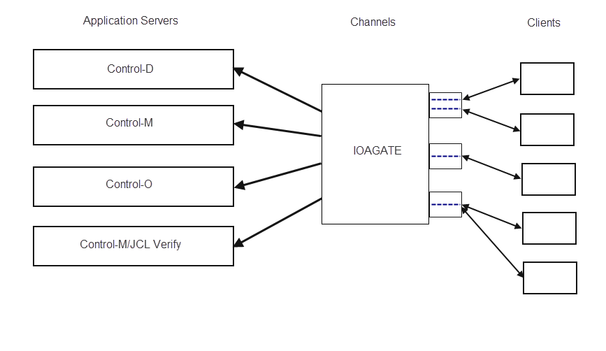
The following INCONTROL products are supported:
Table 34 INCONTROL Products Supported by IOAGATE
|
INCONTROL application |
Short code |
Application server address space procedure |
Client side |
|---|---|---|---|
|
Control‑D/Page on Demand (POD) |
D |
IOAAS |
Control‑D/ |
|
Control‑D File Transfer Option (FTO) |
F |
IOAAS |
Control‑D/Agent |
|
Control-M |
C |
CTMCAS |
Control-M Configuration Manager |
|
Control-M |
M |
CTMAS |
Control-M/ |
|
Control‑O |
O |
CTOAS |
Control‑O |
|
Control-M JCL Verify |
J |
CTJAS |
Control-M JCL Verify |
IOAGATE supports multiple concurrent application servers of different applications and their clients. A single IOAGATE can support all the Application Servers shown above.
When you have read IOAGATE Installation and Configuration Considerations mark this step complete.
Step 20.2 – Configure IOAGATE Parameters
Multiple IOAGATEs can be started concurrently.
The parameters of each IOAGATE are defined in the ECAPARMx member of each IOAGATE in the IOA.PARM library, where x is a unique 1‑character suffix to the member name. The specific ECAPARM member to be loaded and used by a specific IOAGATE is specified by the PSFX parameter at IOAGATE startup. For example, PSFX=X is used with the ECAPARMX member.
When this option is selected, the IOAGATE Parameters Menu is displayed:
Figure 26 IOAGATE Parameters Menu
 --------------------------- IOAGATE Parameters Menu -------------------------
                 OPTION  ===>
                 Parameter Member:

                  0  ECAPARMx     - Select the ECAPARMx (x=suffix)
                  1  Application  - Define/Update Application Server
                  2  Channel      - Define/Update Channel
                  3  Global       - Global IOAGATE Parameters (Optional)
4 Build - Build the Parameter Member -
Select option0, ECAPARMx, to specify the name of the ECAPARMx member you want to edit. Type the name and press Enter. The parameter member name you specified is displayed at the top of the IOAGATE Parameters Menu screen.
-
Select option1, Application, to create or update application servers. This is where you specify the application servers in use at your site, meaning, Control-D/Page On Demand and Control-D File Transfer option, Control-M, Control-O, Control-M JCL Verify, or any of these. The Create/Update Application Server screen is displayed:
Figure 27 Create/Update Application Server Screen
 --------------------- Create/Update Application Server ----------------------
                 COMMAND ===>                                              SCROLL ==> CSR

                  Codes in the Sel field:            Command and Keys:
                     D Delete Application Server        Add     To Add an application server
                     A Advanced Parameters              PF3/End Exit

                 Sel  Appl          Channel  Procname
                 ===  ============  ======   ========
             ******************************* Bottom of data ******************************
From this screen you can add a new application, by typing Add in the COMMAND field and pressing Enter.
You can also type the options shown in the following table to perform the actions shown in the table.
Table 35 Options in the Create/Update Application Server Screen
|
Option |
Description |
|---|---|
|
D |
Delete an application server. For more information, see Delete an Application Server. |
|
A |
Insert values for advanced parameters. For more information, see Advanced Parameters. |
Add a New Application Server
When you type Add in the COMMAND field, the Add New Application Server screen is displayed:
Figure 28 Add New Application Server Screen
------------------------- Add New Application Server ------------------
                COMMAND ===>

                 Type Application Server details and press Enter to Save
                 Press PF3 to exit

                    Application. ==>     D Control-D/POD    M Control-M     O Control-O
                                         F Control-D/FTO    C Control-M/CM

                    Channel..... ==>


                    Procedure... ==>    Defaults: IOAAS  - for Application D/F
                                                  CTMAS  - for Application M
                                                  CTOAS  - for Application O
                                                  CTMCAS - for Application C
                                              CTJAS  - for Application J
For each application server you want to add, insert values for the parameters shown in the following table and press Enter.
A multiple number of application server definitions can be created in one ECAPARM member. Each ECAPARM APSERVER statement generated by the Add function defines one Application Server address space. The maximum number of application server address spaces per channel is 8.
If the Control-M Application Server (CTMAS) or the Control-M Configuration Manager Application Server (CTMCAS) are to be used, Control-M/Enterprise Manager 6.3.xx must already be installed and running on either the UNIX or the Windows side of the connection. For more information, see Step 21 – Install Control-M Application Server.
The Control‑D/Page On Demand (D) application supports multiple Application Server address spaces for the same application.
For a large number of concurrent connections (100 or more), it is recommended that at least 4 application servers be defined.
Table 36 Parameters for the Add New Application Server Screen
|
Parameter |
Description |
|---|---|
|
Application |
1-character code for the Application Server to be added. Valid values are:
|
|
Channel |
Two alphanumeric characters that serve as an ID to designate the channel for the application server being added. This ID is referred to when the channel is defined. |
|
Procedure |
Name of the procedure that IOAGATE must run when it starts the application server. The following default values will be used if none is coded:
|
Delete an Application Server
Type D in the Sel field of any row containing an Application Server, and press Enter. The Application Server definition is deleted.
Advanced Parameters
To insert values for advanced parameters, type A in the Sel field of any row containing an Application Server. The following screen is displayed:
Figure 29 Application Server Advanced Parameters Screen
 ------------------- Application Server Advanced Parameters ------------------
                 COMMAND ===>

                  Fill the following fields and press Enter to Save
                  Press PF3 to exit

                  Application name: M             Channel: O1      Procname: CTMAS

                 Non-Swappable............(NONSWAP)  ==>           (YES/NO)
                 Compression..............(COMPRESS) ==>           (YES/NO)
                 No. of server tasks......(NUMSRV)   ==>           (1-200 For Appl=D,F only)
                 Automatic recoveries.....(MAXRECOV) ==>           (0-99)
                 Encryption     ..........(ENCRYPT)  ==>           (NO,YES)for Appl=D
                 Enable/Disable...........(SERVER)   ==>           (Enable/Disable)

                 Time intervals
                 --------------
                 Server wait interval.....(SLEEPINT) ==>           (3-30   sec)
                 Server timeout...........(TIMEOUT)  ==>           (1-7200 sec)
                 Service duration.........(SERVDUR)  ==>           (0-3600 sec)
                 Warning repeater.........(NWARNING) ==>           (0-99 SERVDUR interval)
                 Startup duration.........(STRTDUR)  ==>           (30-999 sec)
                 Abnormal status duration.(STATDUR)  ==>           (0-7200 sec)
             Busy duration threshold..(BUSYDUR)  ==>           (0-999  min)
The parameters in this screen have defaults that generally need not be changed. First-time installers should refrain from changing them.
Table 37 Application Server Advanced Parameters
|
Parameter |
Description |
|---|---|
|
NONSWAP |
Whether the Application Server address space is non-swappable. Valid values are:
|
|
COMPRESS |
Whether the Application Server messages are compressed. Valid values are:
The default depends on the application code, as follows:
|
|
NUMSRV |
The number of identical Application Server tasks that can be attached within the application server address space. This parameter is used by the Control‑D Page On Demand and the Control‑D File Transfer options. The number of Application Server tasks that can be specified and attached primarily depends upon the specific application. Each Application Server task can serve multiple clients serially. It is allocated to a specific client only for the duration of the exchange of a single request or response.
In practice the upper limit may be lower than 200 due to resource constraints, such as lack of storage in the IOAGATE address space or in the application server address space or in both. As a general rule, avoid exceeding a value of 50. If you require more than 50 servers, define additional Application Server address spaces. The combined number of application address spaces per IOAGATE is 99. The maximum number of application server address spaces per channel is 8. BMC recommends not exceeding a total of 500 application server tasks in all application address spaces combined. |
|
MAXRECOV |
The maximum number of permitted subsequent automatic recoveries. For more information about the interval between recovery attempts, and what constitutes a new failure, see "RECVRSET" in Global IOAGATE Parameters.
If MAXRECOV is set to 0, automatic recovery is disabled for this Application Server address space. |
|
ENCRYPT |
Whether data transfer encryption is performed with Control‑D/WebAccess Server. Valid values are:
Beginning with version 6.1.00, IOAGATE enables data transfer encryption with Control‑D/Web Access Server version 3.2.00 installations. The encryption process requires a KEYS file. This KEYS file is generated on the Control‑D/WebAccess Server installation by means of the BMC-ECA-KEYGEN.EXE application. Use FTP and ASCII mode to transfer the generated KEYS file to the z/OS installation where IOAGATE is running. The name of the KEYS file must comply with the following rules:
If the default name is unsuitable, you can define another name, using one of the following methods:
You must protect the KEYS file from access by unauthorized users, but IOAGATE must have authorized READ access to the KEYS file. |
|
SERVER |
Enable or disable the Application Server indicator during this IOAGATE run. Valid values are
|
|
SLEEPINT |
The sleep time interval for Application Server tasks, in seconds. The Control-M Application Server uses this parameter.
|
|
TIMEOUT |
Sets the application server timeout (in seconds). The function of the parameter is determined by the application. This parameter is used only by the Control‑D (and Control‑D File Transfer Option) Application servers to determine the user inactivity period. After that period has elapsed, the server will log the user off automatically if another user logs on.
|
|
SERVDUR |
Sets the allowable interval (interval) of any service (transaction), in seconds. When a service exceeds this interval, a warning message is issued. When SERVDUR is set to 0, the check is disabled.
|
|
NWARNING |
Controls the frequency of reporting about long running transactions using message ECAB43W, which is described in the INCONTROL for z/OS Messages Manual. When a transaction runs longer than the threshold defined by the SERVDUR parameter, IOAGATE does one of the following:
The value of NWARNING sets the number of SERVDUR interval periods before a second or subsequent ECAB43W warning message is issued. Valid values are from 0 through 99. The default depends on the application code, as follows:
|
|
STRTDUR |
Sets the maximum duration of the Start or Recovery process of an Application Server address space or application server, in seconds. When the Start or Recovery duration exceeds this value, a warning message is issued.
|
|
STATDUR |
Sets the maximum duration for an Application Server task in an abnormal status before a warning message is issued.
If STATDUR is set to 0, no warning is sent. There can be several abnormal statuses such as: PENDING, SUSPEND, WAIT. |
|
BUSYDUR |
Sets the maximum duration of Busy status for an application server task. If an application server task remains in Busy status longer than the BUSYDUR value, the server task is presumed to be hung, and it is recycled. Valid values are: 0‑999 minutes The default depends on the application code, as follows:
|
When you have finished inserting values for advanced parameters, press Enter to save these values, and then press End to return to the Create/Update Application Server screen.
Creating/Updating Channels
-
Select option 2, Channel, to create and/or update channels.
-
The Create/Update Channel screen displays.
Figure 30 Create/Update Channel Screen
 ---------------------------- Create/Update Channel --------------------------
                  COMMAND ===>                                              SCROLL ==> CSR

                   Codes in the Sel field:           Command and Keys:
                      D Delete Channel                  Add     To Add a Channel
                      A Advanced Parameters             PF3/End Exit


                  Sel  Id  Model     Protocol  Port   APPLID
                  ===  ==  ========  ========  =====  ========
              ****************************** Bottom of data ******************************
From this screen you can add a new channel, as described in the following section, Adding Channels.
You can also type the options shown in the following table to perform the actions shown in the table.
Table 38 Options in the Create/Update Channel Screen
|
Option |
Description |
|---|---|
|
D |
Delete an existing channel. For more information, see Deleting an Existing Channel. |
|
A |
Insert values for advanced parameters. For more information, see Specifying Advanced Channel Parameters. |
Adding Channels
Type Add in the COMMAND field in the Create/Update Channel screen, and press Enter.
The Add New Channel screen is displayed.
Figure 31 Add New Channel Screen
------------------------------- Add New Channel ------------------------------
                 COMMAND ===>

                 Type Channel details and press Enter to Save
                 Press PF3 to exit

                   Channel ID........................... ==>

                   Communication Model.................. ==>                       (MC/DC)

                   Communication Protocol............... ==>                       (TCP/SNA)

                   TCP/IP port number................... ==>                       (1024-65534)

                   VTAM LU6.2 APPLID.................... ==>

                   IP Addresses Validation.............. ==> NO                    (Yes/No)
                   ECAIPLS Member Name suffix........... ==>

                --------------------------------------------------------
                PORT specification:
                The following default IOAGATE ports are defined on the desktop side:
                2370 for CTMAS communications with CTM/EM
                2369 for CTMCAS communications with CTM/CM
            If you want to use the desktop defaults then specify these ports accordingly here.
For each channel you want to add, do the following:
-
Insert values for the parameters shown in the following table.
-
When you have finished entering values for the parameters of that channel, press Enter.
Table 39 Parameters for Adding a New Channel
|
Parameter |
Description |
|---|---|
|
Channel ID |
A unique 2-character (alphanumeric) channel identifier. This must be identical with the identifier specified in the Channel parameter in the Add New Application Server screen.
|
|
Communication Model |
The channel communication model.
This parameter is always set to:
|
|
Communication Protocol |
The communication protocol used by this channel.
This parameter is always set to TCP. |
|
TCP/IP port number |
TCP/IP port number. This parameter determines the numbers of communication ports used by the channel to listen for connections.
Verify that each of the port numbers is available before continuing with the installation procedure. |
|
VTAM LU6.2 APPLID |
VTAM LU6.2 application ID used by this IOAGATE to communicate over the SNA (APPC) network. This parameter can be used only with a SNA protocol and when a Multiple Connection Model is used. |
|
IP Addresses Validation ECAIPLS Member Name suffix |
An optional member name in IOA PARM including a list of valid IP addresses from which IOAGATE should accept connection established requests (IP list). Valid member name is ECAIPLSx. The following steps must be performed to validate an incoming IP address: Create an IP list. For more information, refer to the ECAIPLS member in the IOA SAMPLE library, and to Validation of an Incoming IP Address for coding guidelines. Insert the created IP list into the IOA.PARM library under the name ECAIPLS. In this syntax x is a one character optional suffix. Specify IPLIST=ECAIPLSx channel parameter in ECAPARM. Both the MC and DC TCP/IP channel of IOAGATE accept the IPLIST parameter. |
When you have finished adding new channels, press PF03/PF15. The channels will be displayed on the Create/Update Channel screen.
Deleting an Existing Channel
Type D in the Sel field of any row containing a channel and press Enter. The channel defined in that row is deleted.
Specifying Advanced Channel Parameters
To specify advanced parameters, do the following:
-
Type A in the Sel field of any row containing a channel.
-
Insert values for the advanced parameters you want to specify.
-
Press Enter to save these values.
-
Press End to return to the Create/Update Channel screen.
Different advanced parameters are displayed according to the type of channel you are updating. The following table contains an inclusive list of all the advanced parameters that can be specified:
Table 40 Advanced Parameters for Creating/Updating Channels
|
Parameter |
Description |
|---|---|
|
TCPVENDR |
TCP/IP software vendor. Determines whether communication is effected over either the IBM TCP/IP software or the CA SNS/TCPaccess software. You can only enter a value for this parameter if you are using TCP/IP. Valid values are:
All TCP channels used by a specific IOAGATE must have the same vendor. |
|
LOGINMSG |
This parameter controls the destinations where ECAG62I messages will be sent. The ECAG62I message indicates that a user successfully logged on to IOAGATE over a multiple connection (MC) TCP channel. Valid values are:
Default: LOG (DAIGLOG) You can display and modify LOGINMSG parameter values as follows:
|
|
SUBSYSTM |
Subsystem name for SNS/TCPaccess. Determines whether the channel should use a non-default subsystem name for the CA SNS/TCPaccess software. Can be used only if the protocol used is TCP/IP, the software vendor used is CA and a non-default subsystem name for SNS/TCP access is required. Valid values are: 4 alphanumeric characters of the subsystem name. There is no need to specify the default subsystem name (ACSS) for SNS/TCPaccess. |
|
COMTASK |
Number of TCP/IP communication tasks to be attached to establish the multiple connection model channel. Can be used only if the protocol used is TCP and a multiple connection model is used. Valid values are: 1 through 100. Default: 4. For application C, COMTASK is always set to 1. Also see below, the note for COMTASK and UPERTASK. |
|
UPERTASK |
Maximum number of users per communication task. Can be used only if the TCP/IP protocol and a multiple connection model is used. Valid values are: 1 through 500. Default: 200. For application C, UPERTASK is always set to 1. Note for both COMTASK and UPERTASK: The maximum values of 100, for COMTASK, and 500, for UPERTASK, are theoretical maximums. It is possible to define thousands of connections for supporting Control-D/WebAccess. The practical maximum of connections per IOAGATE is determined by tuning, which is dependent upon the capacity of the application servers (IOAAS address spaces). This capacity depends on the usage profile, which is defined by the activities of the users and transactions, and the frequency of the transactions. By rule of thumb the following limits exist for supporting Control-D/WebAccess users:
The above yields 8 x 800 = 6400 connections per IOAGATE. The 6400 connections can be supported by 16 communication tasks, each with 400 connections (COMTASK=16, UPERTASK=400). If more than 16 processors exist on the LPAR, then the number of communication tasks can be increased to the number of processors (and the number of connections per communication task can be reduced accordingly). For a large number of concurrent connections (100 or more), it is recommended that UPERTASK be at least 200. |
|
SOCKIMP |
If integrated sockets are in use. Valid values are:
If TCPAccess is in use, and you have set it up to run with OMVS(OE), you must set SOCKIMP to OE. For more information, see Step 20.6 – Set up IOAGATE to Support TCPAccess (Optional). |
|
CHANNEL |
Enable or disable channel indicator. Determines whether the entire current CHANNEL declaration should be used or ignored in this current IOAGATE run. Valid values are:
|
|
The following channel parameters are relevant only for channels used by Control-O or Control-M JCL Verify: |
|
|
NODE |
Node ID. Determines the NODE ID that identifies this IOAGATE. Must correspond to a NODE parameter defined in the network map specified by the NETWMAP parameter.
|
|
NETWMAP |
Network map to be used in the node. Determines the name of the member in the IOA.PARM library that describes an IOAGATE communication network map that allows one IOAGATE to communicate with another. Any IOAGATE that belongs to this Network must use the same network map.
|
|
ALLOCINT |
Interval between allocation attempts, in seconds. Sets a time interval between persistent allocation attempts that IOAGATE performs against its other IOAGATE partners specified in the network map. Valid only for SNA and Control-O.
|
|
LOGMODE |
Default Logmode to be used in allocations. Determines the default Logmode to be used when establishing communication with a partner specified in the network map. Valid only for SNA and Control-O.
|
|
BIND |
IP address that IOAGATE must use to listen for incoming connections. If you want IOAGATE to listen on a specific IP address, such as a DVIPA assigned for IOAGATE, use this parameter to identify that IP address. Use the following syntax: BIND=INADDR_ANY | IP_address | hostname where
|
|
ESOCKAPI |
TCP/IP socket API type. Valid values:
When SAS is specified, IOAGATE uses SAS/C written modules and TCP/IP support is the same as for INCONTROL version 8.0.00 (IPv6 not supported) for this channel. The ESTACK parameter is ignored. When IBM is specified or implied, IOAGATE uses IBM C-written modules and support IPv6 and dual TCP/IP stacks for this channel. SOCKIMP, SUBSYSTM, and TCPVENDOR parameters are ignored. |
|
ESTACK |
TCP/IP stack name. This is the started task name of a TCP/IP stack that is active on the z/OS system. If specified, IOAGATE will establish stack affinity to this stack. Default: The z/OS system's default TCP/IP stack is used. If the z/OS system is not configured for dual stack mode, then the parameter is ignored. But if it is and the stack is not running, then the IOAGATE channel will be disabled. Warning: Specifying a stack may affect connectivity and hostname resolution. Consult your network administrator. |
|
IPVMODE |
TCP/IP protocol implementation level. Valid values:
When IPV4 is specified, IPv6 is not supported. |
|
The following parameters are relevant for SSL support: |
|
|
SSL |
Determines whether SSL support is required. SSL can be specified when the value of PROTOCOL is TCP for both MODEL=DC and MODEL=MC channels. Valid values are:
|
|
KEYRING |
SAF name (RACF or compatible) of a KEYRING associated with IOAGATE.
Valid values are in a string not longer than 47 characters, in the following formats:
|
|
KEYRLAB |
KEYRING label. The LABEL (ID) of the IOAGATE certificate. Optional parameter, relevant only when SSL=YES. Specifies the label of the key used to authenticate IOAGATE. The default key will be used if a key label is not specified. Valid values are in a string not longer than 32 characters. Blanks are allowed inside the string, but if blanks are used the string should be closed with apostrophes. |
|
CLIAUTH |
CLIENT AUTHENTICATION. Determines whether client authentication is required. Optional parameter, relevant only when SSL=YES. SSL client authentication enables a server application (IOAGATE) to confirm the identity of the client application (such as Control-M/EM). The server application verifies that the client certificate and public key are valid and has been signed by a trusted certificate authority (CA) that is known to the server application. In order to be able to perform this verification, the certificate of the CA that has signed the certificate of the client must be added to the KEYRING. Valid values are:
When CLIAUTH=No, only server authentication is performed by the client. |
|
SSLPROT |
Optional advanced choice of SSL protocol(s), for when SSL=YES. The parameter is based on two parameters: SSLPROT=(SSLPRLVL,SSLPRMOD) where
|
Global IOAGATE Parameters
In the IOAGATE Parameters Menu screen, option 3, Global, updates global IOAGATE parameters. This step is optional.
Type 3 in the OPTION field and press Enter. The Parameter Data Entry screen is displayed.
The parameters of the Parameter Data Entry screen have defaults that generally need not be changed. First-time installers should refrain from changing them.
Table 41 Parameter Data Entry Screen Parameters
|
Parameter |
Description |
|---|---|
|
STAYUP |
Whether IOAGATE should stay up when all application server address spaces have failed. Determines whether IOAGATE should continue running when all application server address spaces failed and cannot be recovered. Valid values are:
|
|
SLEEPINT |
IOAGATE sleeping interval in seconds. The sleeping time interval defines for how long the main task of IOAGATE will relinquish control when it is inactive.
|
|
NONSWAP |
Whether the IOAGATE address space is non‑swappable. Valid values are:
|
|
RECVRSET |
Recovery reset time interval, in seconds. The RECVRSET works in conjunction with the MAXRECOV parameter. MAXRECOV limits the number of automatic recovery attempts of an application server address space or an application server task failure. This limits the number of attempts to restore the same application server address space failure or task recurring failure, but allows recovery attempts of new failures. The value assigned to the RECVRSET parameter distinguishes between another recovery attempt for the previous failure and a recovery attempt for a new failure. A recovery attempt with an interval greater than this recovery rate value is not considered a subsequent recovery attempt, but rather, a new failure.
|
|
STAT |
Whether statistics collection should be initiated at IOAGATE startup. Valid values are:
It is also possible to manually start statistics collection at any time by using the STATON modify command. |
|
STATINTR |
Sets the statistics collection time interval, in minutes. Statistics are summarized in STATINTR periods. IOAGATE keeps only the last 6 periods in memory.
|
|
ARMELEM |
The name that represents IOAGATE as an element of Automatic Restart Management (ARM). When this parameter is enabled, the operating system automatically restarts IOAGATE after an unexpected failure, using ARM. When specifying an element name, apply the following rules:
Valid values are:
This element name must exactly match the ELEMENT ARM policy parameter, or the operating system will use the default policy. For more information, see IOAGATE Installation and Configuration Considerations mark and the section on Automatic Restart Management support in the Control-M chapter of the INCONTROL for z/OS Administrator Guide. |
|
HANGDINT |
Hanging detection time interval. The hanging detection mechanism detects hanging situations where the application server, or IOAGATE itself, or the channel, seems to be hanging. The detection principle is based on checking whether messages are being accumulated for the application server, but those messages are not actually being passed to the server. Checking also involves determining whether messages are being accumulated to be passed to a channel, but are not passed to the channel. Hanging detection is activated once each number of HANGDINT seconds. A warning is issued when a hanging situation exists for the last HANGDNIN intervals of HANGDINT seconds.
|
|
HANGDNIN |
Number of hanging detection intervals. This parameter is used to determine the number of consecutive HANGDINT intervals, in which a hanging situation has been detected, that may occur before a warning message is issued.
|
|
ASINTDUR |
The interval during which IOAGATE waits silently for at least one Application Server task to be ready. The following message is issued when this time interval expires. ECAE53W NO APPLICATION SERVER HAS BECOME AVAILABLE to IOAGATE in the last <n> minutes
|
|
ASINTWRN |
The interval between the first time the ECAE53W message is issued and the subsequent occurrences, while IOAGATE waits for an Application Server task to be ready.
|
If errors occur while building ECAPARM, the errors are displayed. Correct the errors and select this option again.
When you are satisfied with the values that are displayed, press PF03/PF15. This will save the parameters and exit this screen to the IOAGATE Parameters Menu.
This step will automatically be marked complete.
Build the Parameter Member
In the IOAGATE Parameters Menu screen, option 4, Build, build the IOAGATE parameters member, ECAPARMx, specified in option 0, based on the values specified in steps 1 (Application), 2 (Channel) and 3 (Global).
Special Global IOAGATE Parameters
Certain IOAGATE parameters cannot be set by means of ICE. You can only set these special IOAGATE parameters by adding them manually to the GATEWAY section of ECAPARM.
Table 42 Special CCM Parameters
|
Parameter |
Description |
|---|---|
|
MAXNOSIB |
The maximum number of Service Instance Blocks (SIBs) dedicated by IOAGATE. IOAGATE dedicates a Service Instance Block (SIB) for each incoming or outgoing message. For that purpose, IOAGATE pre-allocates a pool of SIBs. The default number of SIBs in the pool is 10,000, and the maximum is 32,767. You can use this parameter to increase the number of pre-allocated SIBs. The default number is usually adequate for all purposes, and BMC recommends that you do not increase it without first taking steps to ensure that there is no SIB accumulation problem that could be solved without increasing the number. |
|
SELFTEST |
The interval between IOAGATE internal validation tests. At regular intervals, IOAGATE performs internal tests to validate various control blocks. By default, these tests are performed every 3 seconds. By means of this parameter, you can change the length of the intervals between tests. Valid values are from 1 through 300 seconds. These tests involve only small increases in computer overhead. BMC recommends that you do not increase this value unless it is essential to reduce IOAGATE computer consumption to an absolute minimum even when IOAGATE is idle. |
|
RECVTEST |
The interval between IOAGATE internal scans to check if recovery action is needed. At regular intervals, IOAGATE performs internal scans to check whether any action is required to recover failed application server address spaces or subtasks. By default, these tests are performed every 5 seconds. By means of this parameter, you can change the length of the intervals between tests. Valid values are from 1 through 300 seconds. Increasing the value of this parameter can slightly decrease computer overhead. |
|
TRACE |
This parameter is for use in tracing IOAGATE initialization on request by BMC Customer Support. Valid values are:
|
Step 20.3 – Set up IOAGATE Procedure(s)
A default IOAGATE procedure is provided in the PROCJCL library. This IOAGATE procedure is configured to use the ECAPARM member in the IOA.PARM library. This ECAPARM member does not exist until it is built with a blank suffix. The ECAPARM member that is to be loaded and used by an individual IOAGATE is identified by the value x specified in PSFX=x in the procedure used for IOAGATE startup.
For example, the expression PSFX= (with no value), is associated with the ECAPARM member and the expression PSFX=X is associated with the ECAPARMX member.
If more than one IOAGATE will be started, corresponding, unique ECAPARM members must be created, each differentiated by a unique 1‑character suffix in the member name. An individual procedure must be created for each IOAGATE, by duplicating and renaming the provided default procedure. Each procedure must specify its corresponding ECAPARMn suffix in the PSFX parameter.
After you have set up the IOAGATE procedures, mark this step complete.
Step 20.4 – Specify TCPDATA (TCP/IP Only) (Optional)
Defining the TCP/IP Data File
From the MVS TCP/IP perspective, IOAGATE is one of its client applications. As such, IOAGATE needs a client profile data set, hlq.TCPIP.DATA, which is specified using the //SYSTCPD DD statement.
This is the main resolver configuration data set that contains information on the host name, domain origin, and so on. In addition, this data set also contains the TCPIPJOBNAME parameter that identifies the TCP/IP stack to use.
For more information on this data set, see the z/OS V1Rx Communications Server IP Configuration Reference.
When the //SYSTCPD DD statement is not specified, the standard client searches for hlq.TCPIP.DATA in the following sequence:
-
jobname.TCPIP.DATA for batch jobs and started tasks
-
SYS1.TCPPARMS(TCPDATA)
-
TCPIP.TCPIP.DATA
The default hlq distributed with TCP/IP is the string TCPIP. When found, the data set is dynamically allocated.
If the client profile data set name does not conform to the conventions described above, and as a result cannot be found using the standard search order, the data set should be allocated by the //SYSTCPD DD statement. Otherwise, the DD statement can be omitted.
The issue should be discussed and agreed upon with the local MVS/TCP system network staff.
To assign the proper SYSTCPD data set, use the TCPDATA parameter in the IOAGATE member of the PROCJCL library.
When you have specified the TCPDATA, mark this step complete.
Step 20.5 – Specify RACF Authorizations
-
To connect using TCP/IP, you must define a proper OMVS RACF segment for the userID and GroupID associated with the IOAGATE started task.
For details on defining an OMVS RACF segment, see the appropriate IBM documentation for this topic.
Users of TOP/SECRET or ACF/2 should refer to their specific product documentation for details about the equivalent definitions in their environment.
-
If IPv6 is enabled on the system, provide RACF (or other security product) authorization for the IOAGATE user ID to read the following files:
-
/etc/ipnodes
-
Any other files mentioned in the RESOLVER address space SETUP file statements GLOBALIPNODES and DEFAULTIPNODES.
File access authorization is not required if ESOCKAPI=SAS is defined in the CHANNEL statement of the ECAPARM member. However, this option is not recommended. Refer to Table 40 - Advanced parameters for creating/updating channels in Specifying Advanced Channel Parameters.
The specific security product authorization requirements (if any), can be determined by starting IOAGATE and looking for security product error messages (ICH408I for RACF).
Access authorization can be given by enabling read access to the file using the chmod command.
For example (to allow read access for others):
chmod o+r /etc/ipnodes
The following alternative methods for giving access authorization can be used:
-
In the RACF OMVS segment for IOAGATE, set the User Identifier (UID) to the same UID as the owner of the file as displayed by the 'ls –l' command.
-
Connect the IOAGATE UID to the same group as the file's group using the RACF CONNECT command.
-
Step 20.6 – Set up IOAGATE to Support TCPAccess (Optional)
You only need to do the actions described in the following paragraphs if you use TCPAccess at your site.
How you set up IOAGATE to support TCPAccess depends on whether TCPAccess is set up to run with OMVS(OE).
When TCPAccess Has Been Set Up to Run with OMVS(OE)
-
Before setting up IOAGATE, ensure that CA Service Pack SP0112 (or later) for TCPAccess has been applied.
-
For security purposes, define a valid OMVS RACF segment for the userID and GroupID associated with the IOAGATE started task.
-
Configure IOAGATE as follows:
-
Use the CTRANS parameter in the IOAGATE PROCJCL to define the CTRANS library provided by BMC with INCONTROL version 6.1.xx and above. Do not use SASLINK provided by the manufacturers of TCPAccess in IOAGATE.
The default CTRANS value is the same as that used by IOAGATE when working with IBM TCP/IP.
-
Use the TCPDATA parameter to define the appropriate SYSTCPD file in the IOAGATE PROCJCL. The SYSTCPD must include a valid definition for TCPIPJOBNAME.
-
In each channel definition in ECAPARM, define SOCKIMP=OE.
-
When TCPAccess Has Not Been Set Up to Run with OMVS(OE)
Use the CTRANS provided by BMC. Do not use SASLINK provided by the manufacturers of TCPAccess in IOAGATE.
Use the LSCNCOM member provided by the manufacturers of TCPAccess in the SASLINK library.
You can do this, by the following steps:
-
Allocate a PDS library.
-
Ensure that the new PDS library is APF-authorized.
-
Copy into the new library the LSCNCOM member provided by the manufacturers of TCPAccess.
-
Concatenate this library in front of the CTRANS library.
Step 20.7 – Specify VTAM definitions for SNA multiple connection channels (Optional)
Multiple connection channels can only be specified for the Control‑O and Control‑D/Page On Demand application servers.
For an explanation of how to specify the channel connections, see Multiple Connection Channels Using SNA Session Support.
When you have specified VTAM Definitions for SNA, mark this step complete.
Step 21 – Install Control-M Application Server
This step installs the Control-M Application Server. When completed, mark each step complete.
Before proceeding with this step, consider the following:
-
Control-M Application Server can only run if Control-M is installed. If you have no intention of installing Control-M, skip this step.
-
Information relevant to the administration and customization of Control-M Application Server is described in the Control-M chapter in the INCONTROL for z/OS Administrator Guide.
Step 21.1 – Installation Considerations
Relationship between Control-M and Control-M/Enterprise Manager
Control-M/Enterprise Manager (Control-M/EM) is a software product that runs on UNIX and Microsoft Windows workstations to provide centralized control of the job scheduling production environment for the entire enterprise. Control-M/EM advanced graphical user interface provides enhanced perception of production flows throughout the entire active environment.
Control-M/EM works in conjunction with Control-M Production Control Systems and the Control-M/Restart Automated Job Restart System.
One Control-M/EM network has the ability to control multiple Control-M installations on various types of platforms. The following example illustrates communication between Control-M on a z/OS platform with Control-M/EM (using IOAGATE and CTMAS).
Figure 32 Communication between Control-M on a z/OS Platform with Control-M/Enterprise Manager (Using IOAGATE and CTMAS)
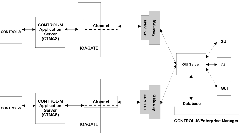
Relationship between Control-M JCL Verify and Control-M/Enterprise Manager
When Control-M JCL Verify is installed, JCL verification requests can be initiated from Control-M/Enterprise Manager. In this case the Control-M Application Server (CTMAS) passes the verification request to the local Control-M JCL Verify monitor (CTJMON), which belongs to the same IOA environment, on the same z/OS system. Remote verification (requests to CTJMONs on other systems) is not supported from Control-M/Enterprise Manager.
Configuring Control-M/CM Application Server (CTMCAS) (Optional)
The Control-M Configuration Manager application server (CTMCAS) is an optional feature which supports Control-M Configuration Manager on Windows.
Control-M Configuration Manager (CCM) enables you to manage all of the administrative tasks of Control-M from one focal location. Using Control-M Configuration Manager you can perform various tasks and configure elements within Control-M.
One of the elements that you can configure is Control-M for z/OS, including the Control-M application server (CTMAS).
CTMCAS together with IOAGATE functions as the Control-M administration agent on z/OS.
It is possible to either dedicate one IOAGATE for CTMCAS and another IOAGATE for CTMAS, or include them both in the same IOAGATE (possibly with other applications).
If the Control-M Configuration Manager does not display updated data about a specific application that you have installed, restart the Control-M Application Server.
When a Control-M for z/OS datacenter is defined in Control-M Configuration Manager, the user can specify either discovery mode or direct mode.
-
Discovery mode means that CCM will discover the existence of CTMAS by establishing a connection with CTMCAS via IOAGATE and retrieving configuration parameters from it. The port configured in CCM in this case is the port on which IOAGATE listens for CCM connections to CTMCAS. The main configuration parameter retrieved from CTMCAS by discovery mode is the port on which IOAGATE listens for the Control-M/EM connection to CTMAS. Please note that these ports are not the same.
-
Direct mode means that the port configured in CCM, in this case, is the port on which IOAGATE listens for CONTOL-M/EM connections to CTMAS. Control-M/EM will directly connect to this port for communications with CTMAS.
The Control-M Configuration Manager application server reports the status of the following Control-M components:
-
IOAGATE
-
Control-M application server
-
Control-M monitors (global and locals)
-
Control-O or CMEM monitors.
The Control-M Configuration Manager application server can also be configured to change the status of the Control-M monitor that it controls according to the Desired State set in the CCM.
The Control-M Configuration Manager application server can either issue a message whenever the actual status of the monitor is different from the desired status, or it can issue an MVS START or STOP command to start or stop the Control-M monitor whenever it needs to be started or stopped.
Software Requirements and Compatibility
To use Control-M Application Server (CTMAS), Control-M/Enterprise Manager must be from the same version and release, or later, as Control-M for z/OS. The version and release are indicated by the v.r.mm format (in earlier versions) or the v.v.rr.mmm format (in more recent versions) in the product description. In this numbering format, v is version, r is release, and m is maintenance level.
In case there is a need to work with an earlier release of Control-M/Enterprise Manager, such as during a testing period, the parameters MODECTM and MODEASM in IOAPARM member must be set to the version of the Control-M/Enterprise Manager. For example, if the Control-M/Enterprise Manager is in V8 and the IOA is in V9, the setting of MODECTM=800 and MODEASM=800 must be used. Setting the value would restrict the functionality of the Control-M for z/OS to the features and parameter values that were in effect in the specified version. See the section on the parameters MODECTM/MODEASM for more detailed explanation on the values and the accompanied restrictions.
Note that BMC does not recommend that this mode be used for a long period of time, but should be limited to only upgrading and testing periods.
If you have any questions, please contact BMC Customer Support.
Step 21.2 – Shout to Control-M/EM Parameters
When a Shout message from Control-M is destined for Control-M/EM, the Shout message is written to the M2G file and distributed to Control-M/EM by the Control-M Application Server. To achieve this, you must insert values for the parameters in the following table:
Table 43 Shout to Control-M/EM Parameters
|
Parameter |
Description |
|---|---|
|
ECSDEST |
Default destination for Shout messages sent to Control-M/EM.
|
|
UECS2ECS |
Whether Shout messages with the DEST destination parameter set to U-ECS should also be sent to Control-M/EM. Valid values are:
|
|
OPER2ECS |
Whether Shout messages whose DEST destination parameter is set to OPER or OPER2 should also be sent to Control-M/EM. Valid values are:
|
|
OPER2CON |
Whether Shout messages with the DEST destination parameter set to OPER or OPER2 should also be sent to the console. Valid values are:
|
|
M2GSIZE |
Size, in blocks, of the Shout to Control-M/EM file, which is also known as the M2G file.
|
Step 21.3 – Remote Force Job Control-M/EM Parameters
When a DO REMFORCE request from Control-M is destined for Control-M/EM, the request is written to the M2F file and distributed to Control-M/EM by the Control-M Application Server.
When a DO REMFORCE request is sent from a remote CONTROL-M via CONTROL-M/EM, the request ID is written to the REQFRC file for tracking purposes.
To achieve this, you must insert values for the parameters in the following table.
Table 44 Remote Force Job Control-M/EM Parameters
|
Parameter |
Description |
|---|---|
|
M2FSIZE |
Size, in blocks, of the Remote Force Job Request file, which is also known as the M2F file. Default: 1000. |
|
REQFRCSZ |
Size, in blocks, of the Remote Force job Requests LOG file, which is also known as the REQFRC file. Default: 1000. |
Step 21.4 – Set ECS to Y in IOAPARM
This step changes the value of the ECS installation parameter to Y. This indicates that the Control-M Application Server is installed. When the process completes, this step is automatically marked complete.
Step 21.5 – Format the Shout Data Set
The FORMM2G job formats the data sets that communicate with the ESCGATE and transfer Shout messages.
Submit the job and verify that all job steps end with a condition code of 0.
Step 21.6 – Minimum Security Authorizations
-
Control-M Application Server can be installed without setting up special security requirements, except as noted below for RACF, CA-ACF2 and CA-TOP SECRET.
If you are using RACF, ACF2 or TOP SECRET, define the started task Control-M/EM as a valid started task under the relevant security system.
-
All Control-M functions that the user specifies by Control-M Application Server are performed in Control-M by Control-M Application Server
To enable Control-M Application Server to perform these functions as required, provide Control-M Application Server with READ and UPDATE authority for all data sets for which the Control-M monitor is authorized.
-
When authorized, users of Control-M Application Server have the option of performing the Edit JCL function. This function is executed by Control-M Application Server. Accordingly, Control-M Application Server should have UPDATE authority for all JCL libraries for which any Control-M Application Server user has EDIT authority.
-
Control-M Application Server performs actions on jobs that are contained in the Active Jobs file and that are displayed in the Active Environment screen (Screen 3). The CTMSE08 Control-M security module verifies a user’s authorization to perform actions on these jobs.
If security for Control-M is enabled, you must authorize Control-M Application Server to perform all operations in Control-M Screen 3.
For more information about the CTMSE08 module, see the Control-M chapter in the INCONTROL for z/OS Security Guide.
-
The following special users must be authorized:
-
User GCSERV: When global conditions are added from the Control-M/EM Global Conditions Server, they are added under userID GCSERV. The GCSERV user therefore must be defined in security.
The GCSERV user is the userID of the Control-M/EM Global Conditions Server that distributes global condition transactions from any data center to another. This user should have the authorization to access IOA Condition file facilities. This userID must be GCSERV, specified with uppercase letters.
-
User CTMAS: The userID that was assigned to the CTMAS monitor that actually performs all Control-M/EM requests in the mainframe data center. This user ID is not necessarily CTMAS, but whatever user ID the system assigns to the CTMAS monitor. This value can be changed.
-
User CTMSYNC: The user ID through which Control-M/EM requests automatic synchronization between the folder libraries in Control-M (specified by SYNCLIBS for synchronization) and the Control-M/EM database. This user must have dataset access authorization to all the libraries specified in the SYNCLIBS parameter member, and to the calendar libraries pointed to by DD names DACAL and DARBC. In addition, in Extended Definition mode, CTMSYNC must have authorization to the $$ECSVWF facility. Note that CTMSYNC is the default user name which is customizable in Control-M/EM, so if it changed the new user name must be authorized in this step.
-
User BIMUSER: BMC Batch Impact Manager requires a user name to connect to Control-M/EM. In Control-M for z/OS, you must add a user that will be used by BMC Batch Impact Manager. By default, BMC Batch Impact Manager uses the BIMUSER user name.
Verify that the BIMUSER user name has the following privileges:
-
Order
-
Force
-
Rerun
-
Hold
-
Log
-
Zoom-and-Save
-
Kill job
For information on setting the privileges for the user name, see the INCONTROL for z/OS Security Guide.
-
-
Step 22 – Install KOA and IOA Routes (Optional)
This step is intended for users who need to install the IOA KeyStroke OpenAccess (KOA) facility that allows logon to VTAM applications.
Step 22.1 – Set Logical Terminals and Routes
Select this step to start a process that defines (or updates) the Logical Terminals and Routes for KOA.
The Logical Terminals and IOA Routes Menu screen is displayed:
Figure 33 Logical Terminals and IOA Routes Menu Screen
-------------------- Logical Terminals and IOA Routes Menu -------------------
                 OPTION  ===>

                 Parameter Member: IOAKPRM

                  1  Global       - Global Parameters
                  2  Terminals    - Define/Update Logical Terminals
                  3  Routes       - Define/Update IOA Routes
                  4  Build        - Build the Parameter Member
              X  Exit         - Leave the Process
Global Parameters
Select option 1, Global, and the Parameter Data Entry screen is displayed:
Figure 34 Parameter Data Entry Screen
---------------------------- Parameter Data Entry ----------------- Row 1 of 9
                COMMAND ===>                                                    SCROLL==> CSR

                Product: IOA          Major Step: 22  Install KOA and IOA Routes
                Environment: DOC700   Minor Step: 1   Set Logical Terminals and Routes

                Codes in the VALUE field:           Function keys and Commands:
                  = Insert from Reference             PF7/8   Scroll through all parameters
                  / Insert from Default               PF3/End Exit and Save
                  ? Display Help                      Cancel  Exit without Save
                ------------------------------------------------------------------------------
                   Variable    Value      Reference   Description
                   =========== ========== =========== ===========
                   KOATIME     60                     Global timeout
                   LTYP2       D4A32782               LOGMODE for model 2 SNA terminals
                   LTYP2XT     SNX32702               LOGMODE for model 2 SNA term. (extended)
                   LTYP3       D4A32783               LOGMODE for model 3 SNA terminals
                   LTYP3XT     SNX32703               LOGMODE for model 3 SNA term. (extended)
                   LTYP4       D4A32784               LOGMODE for model 4 SNA terminals
                   LTYP4XT     SNX32704               LOGMODE for model 4 SNA term. (extended)
                   LTYP5       D4A32785               LOGMODE for model 5 SNA terminals
                   LTYP5XT     SNX32705               LOGMODE for model 5 SNA term. (extended)
            ------------------------------> End of Parameters <---------------------------
Insert values for the parameters described in the following table. All but the first are Logon Mode parameters.
Table 45 Global KOA and IOA Routes Parameters
|
Parameter |
Description |
|---|---|
|
KOATIME |
Time in minutes before a logical terminal is terminated. If Timeout is set to 100, timeout checking is not performed.
|
|
LTYP2 |
LOGMODE for Model 2 SNA terminals.
|
|
LTYP2XT |
LOGMODE for Model 2 SNA terminals that support extended data stream.
|
|
LTYP3 |
LOGMODE for Model 3 SNA terminals.
|
|
LTYP3XT |
LOGMODE for Model 3 SNA terminals that support extended data stream.
|
|
LTYP4 |
LOGMODE for Model 4 SNA terminals.
|
|
LTYP4XT |
LOGMODE for Model 4 SNA terminals that support extended data stream.
|
|
LTYP5 |
LOGMODE for Model 5 SNA terminals.
|
|
LTYP5XT |
LOGMODE for Model 5 SNA terminals that support extended data stream.
|
When you are satisfied with the values you have entered, press PF03/PF15 to exit this screen. The Logical Terminals and IOA Routes Menu screen is displayed again.
Define/Update Logical Terminals
Select option 2, Terminals, and the Update IOA Logical Terminals (KOA) screen is displayed:
Figure 35 Update IOA Logical Terminals (KOA) Screen
--------------------- Update IOA Logical Terminals (KOA) ---------- Row 1 of 6
                COMMAND ===>                                              SCROLL ==> CSR

                 Codes in the Sel field:            Command and Keys:
                    D Delete KOA                       ADD     Add KOA
                    A Add KOA                          CANCEL  Exit without Save
                                                       PF3/End Exit and Save

                Sel    SMFID       PREFIX  TERM#
                ===    ========    ======  =====
                       SMF1         KOA1    10
                       SMF2         KSL2    10
            ******************************* Bottom of data *******************************
From this screen you can add a new logical terminal to KOA, by typing Add in the COMMAND field and pressing Enter.
You can also using the options shown in the following table to perform the actions shown in the table.
Table 46 Options in the Update IOA Logical Terminals (KOA) Screen
|
Code |
Description |
|---|---|
|
D |
Deletes an existing logical terminal. For more information, Add a Logical Terminal. |
|
A |
Adds a logical terminal for KOA. This code performs the same function as the ADD command. For more information, see the following section, Add a Logical Terminal. |
Add a Logical Terminal
When you type Add in the COMMAND field, or A in the Sel field, the Add Logical Terminal (KOA) screen is displayed:
Figure 36 Add Logical Terminal (KOA) Screen
------------------------- Add Logical Terminal (KOA) -------------------------
                COMMAND ===>

                 Type KOA details and press Enter
                 Press PF3 to exit

                     SMFID/System ===>

                     Prefix       ===>

                     Term#        ===>
For each logical terminal that you want to add, insert values for the parameters shown in the following table:
Table 47 Parameters in the Add Logical Terminal (KOA) Screen
|
Parameter |
Description |
|---|---|
|
SMFID |
MVS SMFID of the computer. |
|
PREFIX |
A 4-character common prefix for the KOA logical terminals. Each computer must have a unique prefix. |
|
TERM# |
Number of KOA terminals defined under VTAM for the computer. |
When you are satisfied with the parameter values, press Enter to return to the Update IOA Logical Terminals (KOA) screen, from which you can repeat this procedure to add another logical terminal.
When you are satisfied with the values you have entered, you can do one of the following:
-
type Cancel in the COMMAND field and press Enter, to exit the Update IOA Logical Terminals (KOA) screen without saving
-
press PF03/PF15 to save the defined logical terminals and exit this screen
The Logical Terminals and IOA Routes Menu screen is redisplayed.
Delete a Logical Terminal
Type the letter D in the Sel field of any row containing a logical terminal, then press Enter. The logical terminal definition is deleted.
When you have deleted the logical terminals you wished to delete, press PF03/PF15 to exit this screen.
Define/Update IOA Routes
Select Option 3, Routes, and the Update IOA Routes screen is displayed:
Figure 37 Update IOA Routes Screen
------------------------------ Update IOA Routes -----------------------------
                COMMAND ===>                                              SCROLL ==> CSR

                 Codes in the Sel field:            Command and Keys:
                    D Delete Route                     ADD     Add Route
                    A Add Route                        CANCEL  Exit without Save
                                                       PF3/End Exit and Save

                Sel    SMFID       APPL        NODE
                ===    ========    ====        ====
            ******************************* Bottom of data *******************************
From this screen you can add a new route for KOA, by typing Add in the COMMAND field and pressing Enter.
You can also using the options shown in the following table to perform the actions shown in the table.
Table 48 Options in the Update IOA Routes Screen
|
Code |
Description |
|---|---|
|
D |
Deletes an existing route. For more information, see Delete an IOA Route. |
|
A |
Adds a route for KOA. This code performs the same function as the ADD command. For more information, see Add Route. |
Add Route
When you type Add in the COMMAND field, or A in the Sel field, the Add IOA Route screen is displayed:
Figure 38 Add IOA Route Screen
-------------------------------- Add IOA Route -------------------------------
                COMMAND ===>

                 Type IOA Route details and press Enter
                 Press PF3 to exit

                     SMFID/System ===>

                     Application  ===>

                     Node         ===>
For each IOA route that you want to add, insert values for the parameters shown in the following table:
Table 49 Parameters in the Add IOA Routes Screen
|
Parameter |
Description |
|---|---|
|
SMFID/System |
MVS SMFID of the computer |
|
Application |
A 4-character common prefix for the KOA logical terminals. The prefix must be unique for each computer. |
|
Node |
Number of KOA terminals defined to VTAM for the computer. |
When you are satisfied with the parameter values, press Enter to return to the Update IOA Routes screen, from which you can repeat this procedure to add another IOA route.
When you are satisfied with the values you have entered, press PF03/PF15 to save the defined IOA routes and exit this screen. The Logical Terminals and IOA Routes Menu screen is redisplayed.
Delete an IOA Route
In the Update IOA Routes screen, type the letter D in the Sel field of any row containing an IOA route, then press Enter. The IOA route definition is deleted.
When you have deleted the IOA routes you wished to delete, press PF03/PF15 to exit this screen. The Logical Terminals and IOA Routes Menu screen is redisplayed.
Build the Parameter Member
In the IOAGATE Parameters Menu screen, option 4, Build, build the IOAGATE parameters member, ECAPARMx, specified in option 0, based on the values specified in steps 1 (Application), 2 (Channel) and 3 (Global).
Step 22.2 – Define KOA logical "Terminals" in VTAM
KOA runs as a VTAM application that simulates a terminal. KOA terminals, which are actually VTAM applications, are defined in VTAM in the same way as other logical units in the SNA network. A pool of KOA terminals must be defined for each computer in which KOA scripts can run.
The number of KOA logical terminals defined in VTAM should be greater than the maximum number of KOA scripts that can run in parallel. For example, if 19 KOA scripts are to be run in parallel, you must define at least 20 KOA logical terminals.
MAJOR NODES member in the VTAM definition library, which is usually called SYS1.VTAMLST. In the MAJOR NODES member, there is a separate library definition for each computer.
Within the terminal pool, each terminal name must consist of a prefix comprised of 1 through 4 characters, followed by a 4‑digit index.
Assume that the site has two computers with MVS SMF IDs SYSX and SYSY.
The KOAAPLX member in the SYS1.VTAMLST library in SYSX defines a pool of 50 KOA logical terminals, as follows:
KOAAPLX VBUILD TYPE=APPL
                    KOAX0001 APPL EAS=1,ACBNAME=KOAX0001
                    KOAX0002 APPL EAS=1,ACBNAME=KOAX0002
                    .
                    .
                    .
                KOAX0050 APPL EAS=1,ACBNAME=KOAX0050
The KOAAPLY member in the SYS1.VTAMLST library in SYSY defines a pool of another 20 KOA logical terminals, as follows:
KOAAPLY VBUILD TYPE=APPL
                    KOAY0001 APPL EAS=1,ACBNAME=KOAY0001
                    KOAY0002 APPL EAS=1,ACBNAME=KOAY0002
                    .
                    .
                    .
                KOAY0020 APPL EAS=1,ACBNAME=KOAY0020
Step 22.3 – Select LOGMODE Tables
A Logon Mode, or LOGMODE, is a set of session parameters that identifies the characteristics of the terminal, such as screen size and the ability to display extended data stream, and the protocol it uses to communicate with other VTAM applications. LOGMODEs are grouped in a Logon Mode table, which is called MODETAB.
KOA simulates a SNA LUTYPE2 and supports all models of terminals, models 2, 3, 4, 5, both with and without extended data stream capabilities. Corresponding LOGMODEs must therefore be defined to VTAM. The SYS1.VTAMLST library, which is supplied when installing VTAM, contains (in the MODETAB ISTINCLM) standard required LOGMODEs. However, if other LOGMODEs are used, specify in each terminal definition the MODETAB name where the corresponding LOGMODEs are defined.
KOAY0001 APPL
-
EAS=1,ACBNAME=KOAY0001,MODETAB=MTABKOA
The MTABKOA member in the INSTWORK library contains a sample MODETAB definition.
The following IBM LOGMODEs are available in the default ISTINCLM table supplied with VTAM:
Table 50 IBM LOGMODEs Supplied with VTAM
|
Logmode Name |
Terminal Type |
Screen Size |
Extended Data Stream |
|---|---|---|---|
|
D4A32782 |
2 |
24 x 80 |
No |
|
SNX32702 |
2 |
24 x 80 |
Yes |
|
D4A32783 |
3 |
32 x 80 |
No |
|
SNX32703 |
3 |
32 x 80 |
Yes |
|
D4A32784 |
4 |
43 x 80 |
No |
|
SNX32704 |
4 |
43 x 80 |
Yes |
|
D4A32785 |
5 |
27 x 132 |
No |
|
SNX32705 |
5 |
27 x 132 |
Yes |
Step 22.4 – Activate VTAM Definitions
VTAM definitions must be active before a KOA script can be used.
To activate the definitions manually, use the following VTAM command:
V NET,ACT,ID=major_node_name
Issue this command in each computer where the definitions should be active. For example, in SYSX:
V NET,ACT,ID=KOAAPLX
To activate the definitions permanently, modify the ATCCONxx member (used when VTAM is initialized) in the VTAM definition library of each computer. For example, the ATCCONxx member in SYSX contains the MAJOR NODE name KOAAPLX.
Step 22.5 – CICS Considerations (Optional)
CICS requires that each terminal or terminal type that communicates with it must be defined to CICS before a connection can be established. From the CICS point of view, there is no difference between a real LUTYPE2 terminal and a KOA terminal. Therefore, the KOA terminals must be defined in the same way as all the other terminals are defined. There are several methods for defining a terminal to CICS:
-
Auto-Install program
-
RDO – Resource Definition Online
-
TCT
The best method for defining KOA terminals is Auto-Install. This is the most flexible method, since there is no need to define each individual terminal and the characteristics of the terminal, such as screen size, can be different in each session. A corresponding TYPETERM and terminal MODEL should exist to reflect all different KOA terminals, LUTYPE2 models 2, 3, 4, and 5, with or without extended data stream. At logon, the CICS Auto-Install program chooses a corresponding terminal model according to the LOGMODE supplied by KOA.
Other methods, such as RDO and TCT, can be used, but they are not as flexible. Each KOA terminal should be defined and the characteristics of the terminal should be specified. The LOGMODE parameters that were supplied during session initiation are ignored. This means that KOA is not able to specify the characteristics of the terminal according to script commands such as SCREENSIZE and COLOR.
Step 22.6 – IMS/DC Considerations (Optional)
IMS/DC requires that each terminal used to communicate with it must be defined to IMS/DC before a connection can be established. From the IMS/DC point of view, there is no difference between a real SNA LUTYPE2 terminal and a KOA terminal. Therefore, each KOA terminal must be defined as part of the IMS/DC GEN. This fixes the characteristics of the terminal, and KOA is not able to specify the characteristics of the terminal according to script commands such as SCREENSIZE and COLOR.
Step 22.7 – Other VTAM Applications (Optional)
Most VTAM applications, such as OMEGAMON, TSO, and NETVIEW, can communicate with any terminal that initiates a session with them. This means that there is no need for additional specifications to communicate between KOA and these applications.
Step 23 – Support for Other Products (Optional)
Perform the following steps to support other products that are installed at your site.
Step 23.1 – Support for LIBRARIAN (Optional)
Control-M can submit jobs from members in LIBRARIAN libraries.
To install LIBRARIAN support, you must install the ELIPS TSO-LIBRARIAN interface. This interface supplies the necessary TSO and ISPF services to Control-M.
LIBRARIAN libraries with any DSORG except PO are supported. To include LIBRARIAN support in Control-M, select this step and edit member LINKLIBR in the INSTWORK library.
Change the library referenced by the SYSLIB DD statement to the LIBRARIAN load modules library, submit the job, and save the member.
All steps must complete with a condition code of 0.
Sample Exit CTMX014L must be installed.
All appropriate LIBRARIAN files should be added to the ISPxLIB DD statements in the IOA TSO logon procedures.
Repeat this process each time you change your LIBRARIAN version. Otherwise, submission results may be unpredictable.
When Control-M is installed, LIBRARIAN option "‑INC" is not resolved during job submission.
To support the LIBRARIAN‑INC command, apply Wish WI0880, located in the IOADFLT member in the IOA IOAENV library.
Because an error in the above‑mentioned linkage procedures can cause serious errors in the Control-M monitor, you must test LIBRARIAN support under the AutoEdit submission simulation before attempting to install it under the Control-M monitor.
Step 23.2 – Support for PANVALET (Optional)
Control-M may submit jobs from members in PANVALET libraries. To include PANVALET support in Control-M, select this step and edit the LINKPANV member in the INSTWORK library.
Change the library defined by the SYSLIB DD statement to the PANVALET load modules library, submit the job, and save the member.
All steps must complete with a condition code of 0.
Repeat this process each time you change your PANVALET version. Otherwise, submission results may be unpredictable.
BMC recommends that PANVALET support be tested under the AutoEdit submission simulation before attempting it under the Control-M monitor. An error in the above‑mentioned linkage procedures may cause serious errors in the Control-M monitor.
For PANVALET versions 14 and later, certain modules are fetched dynamically during execution. For this reason, the PANVALET Load library must be referenced in either the STEPLIB DD statement of the Control-M monitor procedure or the MVS Linklist library.
The PANVALET LOAD library must also be APF-authorized.
Step 24 - Java and z/OS Unix Components Configuration
Follow these steps to install z/OS UNIX components support in IOA, which is required for the Control-M API Gateway.
Step 24.1 – Installation Considerations
The following steps define the zFS filesystem- related parameters, create the filesystem VSAM data set, format the filesystem, and mount it.
The zFS VSAM data set and the zFS filesystem are created and maintained by this ICE only and cannot be shared between, or swapped with, filesystems from other IOA environments.
The TSO user who performs the installation must have ALTER authority to the IOA zFS VSAM LDS and SUPERUSER authority for zUNIX files (UID 0 or READ access to FACILITY BPX.SUPERUSER files).
After installation of z/OS UNIX support is completed, it is highly recommended that you add automount definitions for this zFS filesystem to the SYS1.PARMLIB(BPXPRMxx) member, so that you do not forget to mount the filesystem. Control-M API Gateway will not start if the filesystem is unmounted.
Step 24.2 – Provide Java and z/OS Unix Parameters
This step defines and validates the parameters required to allocate, format, and mount the zFS filesystem .
Table 50a zFS Filesystem Parameters
|
Parameter |
Description |
|---|---|
|
IOAJAVAH |
Full absolute path of the Java home directory used by INCONTROL components. Default: |
|
IOAJAVAP |
The full name of the procedure that launches the Java used by INCONTROL components. Default: |
|
IUFSMNTP |
The full, absolute path to a UNIX directory that serves as the z/OS UNIX mount point for the zFS filesystem created by ICE for use by INCONTROL components. This directory is not created by ICE. Therefore, before defining the value of this parameter, ensure that the directory exists and is empty. The filesystem belongs to this IOA environment only and cannot be shared between IOA environments or swapped with another IOA environment. ICE checks its ownership over the filesystem each time before writing to it. Default: /usr/lpp/bmc/<ilprefa prefix in lower case>/ |
|
The effective user ID for Control-M API Gateway and the owner of the files in the UNIX filesystem created by ICE. The entry for this user ID in the SAF security product in use (such as RACF) must have a TSO segment defined. Default: TSO User ID of the user who installed the IOA environment |
|
|
IUFSDSN |
The name of the zFS VSAM data set that ICE will create, format, mount, and populate. The filesystem belongs to this IOA environment only and cannot be shared between IOA environments or swapped with another IOA environment. ICE checks its ownership over the filesystem each time before writing to it. Default: ilprefa.ZFS |
|
IUFSUNIT |
The unit name used by ICE to allocate the z/OS UNIX Filesystem VSAM data set. Default: Unit of IOA Installation Libraries |
|
IUFSVOL |
The name of the volume used by ICE to allocate the z/OS UNIX Filesystem VSAM data set. Default: Volser (volume serial) of IOA Installation Libraries |
|
IUFSDC |
The name of the data class used by ICE to allocate the z/OS UNIX Filesystem VSAM data set. Default: Data class of IOA Installation Libraries |
|
IUFSMC |
The name of the management class used by ICE to allocate the z/OS UNIX Filesystem VSAM data set. Default: Management class of IOA Installation Libraries |
|
IUFSSC |
The name of the storage class used by ICE to allocate the z/OS UNIX Filesystem VSAM data set. Default: Storage class of IOA Installation Libraries |
Step 24.3 – Allocate and Format zFS VSAM Data Set
This step allocates a zFS VSAM data set and creates a zFS filesystem within the data set. It then mounts the filesystem, so that it is ready for the propagation process.
The TSO User who performs this step must have ALTER authority to the IOA zFS VSAM LDS and SUPERUSER authority for zUNIX files (UID 0 or READ access to FACILITY BPX.SUPERUSER files).
It is highly recommended to add automount definitions for this zFS filesystem to the SYS1.PARMLIB(BPXPRMxx) member, so that you do not forget to mount the filesystem.
The zFS VSAM data set and the zFS filesystem are created and maintained by this ICE only, and can not be shared between, or swapped with, filesystems from other IOA environments.
Step 24.4 – Indicate zFS Support is Installed
This step indicates that zFS Support is installed and the filesystem is ready for use. This step must be performed to make it possible to propagate INCONTROL elements to the zFS filesystem.
Step 25 - Installation Conclusion
This step is used to indicate that IOA installation is complete.
After installation of the products is complete, JCL procedures, User Exits, and other components of the product can be customized to further meet your site requirements. BMC recommends that you log all such changes in a readily available customization log. This log can then be used in future installations of the product, or when copying the product into additional environments.
BMC recommends that you include the following details for each entry in the customization log:
-
the serial number and identifier
-
the date of the change
-
the function and purpose of the change
-
a description of the change
Step 25.1 – Indicate Installation Concluded
This step updates the Status field in the Environment Table to indicate that IOA is installed.
Step 25.2 – Back up the Installed Environment
BMC recommends that you create a current backup of the IOA libraries.
When backing up the installed environment, verify that the base libraries, installation libraries, operations libraries, and SMP‑related data sets are backed up. This backup can help you to restore the original IOA environment when required, so that IOA or an INCONTROL product can be reinstalled if a significant number of changes are made to the parameters, or when an unrecoverable failure occurs during installation.
Installing Control-M
The following topics describe the steps required to install Control-M. The installation procedure contains step-by-step instructions that correspond to the major and minor steps in the INCONTROL Installation and Customization Engine (ICE).
If you are not familiar with ICE, review Performing Tasks Common to All Product Installations before proceeding with the Control-M installation below.
Before You Begin
For a full list of Control-M libraries, INCONTROL Product Data Sets.
To prepare for the ICE installation, do the following:
-
Open the IOA Installation—Main menu.
-
Type 3 in the OPTION field to select option 3, "INSTALL CTx", and press Enter.
-
Type CTM in the ProductID field.
The Major Steps Selection screen for Control-M is displayed.
You are now ready to install Control-M using ICE.
Control-M Step Checklist
The following list is a summary of the steps required to install Control-M. Detailed step-by-step instructions follow.
Installation Steps
Follow the major and minor steps below to install Control-M using ICE.
Because all jobs submitted during the installation process are tailored as needed, all members referenced in the installation process are located in the ilprefa.INSTWORK library unless specified otherwise.
Step 1 – Planning
Plan the installation process carefully. The Control-M Installation Sheet will help you determine the items you should consider before installing Control-M.
Find out if you require input from system programmers, security administrators and other personnel at your site. Check whether any system changes that require special authorization and processing are necessary. Before proceeding with Control-M installation verify that all necessary configurations are known and planned in advance.
Step 1.1 – Is the Planning Sheet Complete?
This step verifies that you have filled in the Control-M planning sheet.
When you have done so, do the following:
-
Press PF03/PF15 to exit this screen.
-
Type C in the Sel field.
-
Press Enter.
The step will be marked as completed.
Step 2 – Specify Control-M Parameters
Insert values for the installation parameters, which are described briefly in this section.
Step 2.1 – Control-M Operational Parameters
Table 51 Operational Parameters
|
Parameter |
Description |
|---|---|
|
PROCPRFM |
The first three characters of the Control-M JCL procedures after they are copied to the local MVS procedure library. The value specified for this parameter must not be the same as that specified for the PROCPRFx parameter in IOA and other INCONTROL products.
|
|
INTERVLM |
Sleeping interval of Control-M monitor, in hundredths of a second. The monitor becomes active at the specified intervals and determines which tasks are required from it.
Alternatively, the sleeping interval can be set by the following modify command: The sleeping interval is relevant only when there is little or no Control-M monitor activity. |
|
NONSWAPM |
Whether to make the Control-M monitor non-swappable. Valid values are:
BMC recommends that you make Control-M non‑swappable. Otherwise, Control-M is swapped out on each interval, which may slow down the monitor. This option does not change the storage consumption and paging activity of the Control-M monitor. Setting NONSWAP to Y only orders MVS to alter its regular swapping algorithm to reduce overhead. |
|
CTMPLEX |
Whether to activate the CTMPLEX facility, that is, run the Control-M monitor in Sysplex mode.
Valid values are:
For more information about CTMPLEX, see the Control-M chapter in the INCONTROL for z/OS Administrator Guide. |
|
HLDCLAS |
The automatic held output class to which Control-M sends the MSGCLASS output of the job.
For more information about the HLDCLAS parameter, see Installation Considerations. Warning: If you modify this parameter while jobs are executing using the existing settings, Control-M, when restarted, cannot read the sysouts of those jobs. |
|
PRTCLAS |
Output class to be dynamically changed on DD statements containing sysout parameters relating to jobs submitted by Control-M. The class is changed to the HLDCLAS to prevent printing of the output of the job separately from the syslog output. The change is applied only to the JCL records that are submitted by Control-M. If this parameter is left blank, DD statements containing sysout parameters are not changed. Default is blank. |
|
HIST |
Whether to activate the History Jobs file option.
Valid values are:
For more information, see the following section: Introduction to Control-M -> Functional Approach -> Expanded Control-M Functionality -> History Jobs File in the Control-M for z/OS User Guide. |
|
JRNL |
Whether to activate the Control-M AJF Journaling option.
Valid values are:
For more information, see the following section: Introduction to Control-M -> Functional Approach -> Expanded Control-M Functionality -> Journaling and Restoration Capability in the Control-M for z/OS User Guide and see the Control-M chapter in the INCONTROL for z/OS Administrator Guide. |
|
REUSAPPL |
Specifies the prefix of the application parameter in the Job Schedule Definition, for jobs to be handled by AJF Space Reuse Facility. Valid value is a string not longer than 8 characters. The default value is blank, which means that all jobs may be processed by the AJF Space Reuse Facility (if the value of the REUSTIME parameter is not zero). For further information see the discussion of the Active Jobs File Space Reuse Facility in the INCONTROL for z/OS Administrator Guide. |
|
REUSTIME |
Specifies the retention period (in minutes) for a job in Active Jobs File before it is deleted by AJF Space Reuse facility. Valid values are from 0 to 9999 minutes. Default is zero, which means that AJF Space Reuse Facility is inactive. For further information see the discussion of the Active Jobs File Space Reuse Facility in the INCONTROL for z/OS Administrator Guide. |
|
DOCUT |
Whether the third-party vendor product DOCU/TEXT is installed at the site.
Valid values are:
|
|
JSCAN |
Whether a third-party vendor JOB/SCAN or PRO/JCL product is installed at the site.
Valid values are:
|
|
DAYTIMEM |
The start time of the work day at your site.
The format is: DAYTIMEM = +hhmm or -hhmm where:
This start time defines the beginning of a new work day for Control-M.
Every day at the specified time, the Control-M monitor performs a series of procedures that start a New Day under Control-M. The New Day procedure cleans the Active Jobs File of job orders that completed executing OK and job orders with a MAXWAIT that has expired. For more information about the monitor daily workflow, see the INCONTROL for z/OS Administrator Guide. Most installations use a DAYTIMEM between +0900 and +1400. |
|
|
Warning! BMC recommends that you do not change this parameter once Control-M has been in operation in a production environment, or you may introduce unwanted shifts in scheduling. If, despite this, you want to modify the value of this parameter in your production environment, you must not do so between the time set by the current value of DAYTIMEM and the next occurrence of the time that you intend to set for the new value. If you modify DAYTIMEM during this period, you will cause the following:
|
|
ARMELMNT |
The element name that represents Control-M as an element of automatic restart management (ARM). This element name must exactly match the ELEMENT and ELEMENT_NAME ARM policy parameters, or the operating system will use the default policy. For more information, see the section on ARM support in the Control-M chapter of the INCONTROL for z/OS Administrator Guide, and see "ARMELMNT" in the Control-M customization considerations section in the Customizing INCONTROL products chapter in the INCONTROL for z/OS Installation Guide: Customizing. |
|
HCHECKER |
Whether Control-M monitor should use the Health Checker interface to communicate with IBM Health Checker.
Valid values are:
|
|
HCMINTRV |
The interval of time, in minutes, between parameter checks. Each check verifies that the parameter values in the CTMPARM member in the IOA PARM library are the same as the CTMPARM settings currently in memory. If this parameter is set to 0, the check is not processed.
|
|
HCPINTRV |
The interval of time, in minutes, between checks for job processing delays. An exception message is produced based on internal tables, maintained by the various Control-M subtasks (such as submitter, selector, and spyer), which determines whether a job being processed by these components is experiencing excessive delays. These delays could indicate a job is not responding (hang condition). If this parameter is set to 0, the check is not processed.
|
|
HCTINTRV |
The interval of time, in minutes, between checks of the status of the Active Jobs file. An exception message is produced when the entries as a percentage of the maximum allowed, exceeds the threshold defined in the AJFTHRSH parameter. If this parameter is set to 0, the report is not produced.
|
|
HCJINTRV |
The interval of time, in hours, between checks of the "dormant" jobs in the Active Jobs file. Dormant jobs have been sitting in the Active Jobs file for more than the specified days in the HCJDAYS parameter.
|
|
HCJDAYS |
The number of days that defines a job as "dormant."
|
|
PFMINT |
Control-M performance data is accumulated and written to SMF at given time intervals. This parameter sets the time interval, in minutes, at which the SMF records are written. If the interval is set to 0 or 1440 then one SMF record is written during Control-M Newday processing. You can temporarily change this parameter using the Control-M PERFDATA command. The PFMINT parameter is reset to the value in the CTMPARM member when the Control-M monitor is restarted. For more information on the PERFDATA command, see the INCONTROL for z/OS Administrator Guide.
|
|
PFMSMF |
Specifies the SMF record type used for Control-M performance monitoring. Choose an SMF record type number which is not already in use at your installation. If the value is set to 0 no SMF records are created.
|
|
HCDELAYT |
The minimum time interval in seconds, interpreted as a "process delay" in the Control-M Health Checker. If this parameter is set to 0 the report is not produced.
|
|
MXJINBOR |
The MXJINBOR (MaXimum Jobs IN Bulk Order) determines how many jobs are included in bulk ordering.
|
|
WORKLDPL |
Determines whether Control-M uses global workload policies, local workload policies, or both. Valid values are:
Local workload policies are managed in the IOA W screen, whereas Global workload policies are managed from Control-M/EM GUI and can only be viewed in IOA W screen. |
|
HCLINTRV |
The interval time, in minutes, between checks for issues in the IOALOG Index file. If this parameter is set to 0, the check is not processed.
|
|
HCLOGIDX |
Threshold percentage for the level of correspondence between the IOALOG Index file and the IOA Log. A warning is issued when the IOA log is indexed below this percentage.
|
|
HCMEMA16 |
Threshold amount of virtual storage memory (in megabytes) above the 16MB line. A warning is issued when the amount of available storage memory falls below this value.
|
|
HCMEMB16 |
Threshold amount of virtual storage memory (in kilobytes) below the 16MB line. A warning is issued when the amount of available storage memory falls below this value.
|
|
HCSINTRV |
The interval time, in minutes, between checks for issues in Control-M Monitor virtual storage consumption. If this parameter is set to 0, the check is not processed.
|
|
TPMINTG |
Whether to enable an integration between Control-M and Compuware ThruPut Manager. This integration enhances Control-M job submission comments and adds information to be used by ThruPut Manager. Valid values are:
|
Sysout Archive Allocation Attributes
The following parameters control the sysout archive data set allocations. The sysout archive is associated with the DO SYSOUT F command. Whenever the Control-M monitor activates a sysout archiving request, an archive data set is allocated using the following allocation parameters:
UNIT=arcunit,SPACE=(arcspct,(arcpri#,arcsec#),RLSE)
The use of the RLSE parameter causes Control‑M to release unused space at the end of the archiving function.
Table 52 Sysout Archive Allocation Parameters
|
Parameter |
Description |
|---|---|
|
ARCUNIT |
Unit name for the sysout archive data set. Maximum length: 8 characters. The physical address of a volume can be specified but this method is not recommended. BMC recommends specifying a unit that spans a few volumes, such as SYSDA, 3390, and so on. The volumes must be defined in member VATLSTnn in SYS1.PARMLIB with an attribute of STORAGE. |
|
ARCSPCT |
Allocation type for the sysout archive data set. Valid values are:
|
|
ARCPRI# |
Non-zero primary allocation size for the sysout archive data set.
|
|
ARCSEC# |
Secondary allocation size for the sysout archive data set.
|
|
ARCRET |
Archive retention period in days.
|
|
ARCHFBA |
Whether to create the Archive file with the FBA or the FB record format. Valid values are:
In previous versions, this was optional Wish WM1733. |
|
ARCXOUTP |
Whether the Extended SYSOUT Collection feature is enabled, which copies additional sysout files from the spool to the CDAM file, in addition to the job's first three datasets. The additional files that are read are all the job’s output datasets from the automatic held output class (controlled by the HLDCLAS parameter), with the exception of files with the following DD names: SYSABEND, SYSUDUMP and SYSMDUMP. Control-M reads and copies the first 1000 records of each file (even if the output file contains more records). Valid values are:
|
The archive data set's block size (BLKSIZE) is automatically calculated by Control-M. The logical record length (LRECL) is copied from the input SYSOUT file. The maximum LRECL allowed is 256 characters.
Step 2.2 – Build Control-M Sysplex Member (Optional)
If the CTMPLEX parameter is set to Y in Step 2.1, this step is mandatory.
The CTMPLEX parameter member specifies Control-M Sysplex Installation Parameters. This member contains global parameters for both the entire Control-M Sysplex environment and parameters for each Sysplex member in which the LSM monitor may run.
For more information, see the Control-M chapter in the INCONTROL for z/OS Administrator Guide.
Select this step and press Enter. The Update Control-M Plex (CTMPLEX) screen is displayed.
Figure 39 Update Control-M Plex (CTMPLEX) Screen
Table Header---------------------- Update Control-M Plex (CTMPLEX)  ----------- Row 1 of 1
                COMMAND ===>                                              SCROLL ==> CSR
                 Codes in the Sel field:            Command and Keys:
                    D Delete SYSID                     ADD     Add SYSID
                    A Add SYSID                        CANCEL  Exit without Save
                                                       PF3/End Exit and Save
                Structure name ==> STRUCTNAME
                Work balancing indicator ==> N    (Y/N)
                Max. number of entries in structure ==> 100
                                   ---- Cpacity -----
                Sel    SYSTEMID    Relative   Maximum   PRIORITY
                ===    ========    ========   =======   ========
                       SYS6
            ******************************* Bottom of data *******************************
Global CTMPLEX Parameters
In the following table, the name in parentheses in the Parameters column is the name of the parameter in the CTMPLEX member that is built in this Step.
Table 53 Global CTMPLEX Parameters
|
Parameter |
Description |
|---|---|
|
Structure name (STRUCTNM) |
The name of the Coupling Facility structure to be used during CTMPLEX installation. The Coupling Facility name should be the same name that appears in the active Coupling Facility resource management (CFRM) policy governing the use of the Coupling facility at this installation.
The Coupling facility structure used by CTMPLEX should be available for all Sysplex members in which GSM and LSM monitors may run. For more information regarding CFRM administration, see the IBM MVS documentation about the following:
For example, you can find such documentation in the IBM manual z/OS MVS Setting Up a Sysplex. |
|
Work balancing indicator (BALANCEM) |
Workload Balancing mode indicator.
|
|
Max. number of entries in structure (MAXENTRY) |
The size of the CTMPLEX Coupling Facility structure in units of 4KB blocks. If a smaller structure size is specified in the active CFRM policy, the size from the CFRM policy is used.
Each 4KB block may contain from 1 through 4 jobs, depending on the amount of data in the job scheduling definition. The size of the CTMPLEX Coupling Facility should be large enough to include all active jobs, that is, jobs that passed the Select phase and are "Eligible for Run", but not ended yet, at any moment. For example, if 1,000 jobs are active and each job is 2 records, you must define at least 500 4KB blocks for the size of the CTMPLEX Coupling Facility structure. |
|
Recovery time interval (RECOVERT) |
The time interval (in minutes) between attempts to automatically recover the CTMPLEX Facility in case of Coupling Facility failures. A value of 0 (default) means that no automatic recovery procedure takes place. |
|
Max. number of recovery attempts (RECOVERM) |
The maximum number of attempts to automatically recover the CTMPLEX Facility in case of Coupling Facility failures. A value of 0 (default) means that there is no limit to the number of attempts. |
System(s) CTMPLEX Parameters
For each computer in a Sysplex in which an LSM monitor may run, there is a corresponding section labeled SYSTEM in the CTMPLEX member. The following parameters should be specified.
Table 54 System(s) CTMPLEX Parameters
|
Parameter |
Description |
|---|---|
|
SYSTEMID |
The system identifier. All the systems you specify should be the members of the same Sysplex. The corresponding JES subsystems should share the same SPOOL and CHECKPOINT data sets (that is, the system should be a JES2 multi-access spool (MAS) configuration or a JES3 complex. |
|
Relative (RELCAP) |
Relative capacity of the Sysplex member. This is the number of active jobs (that is, jobs that passed the selected phase but have not yet ended) that typically may be processed concurrently by the Control-M monitor on this system. This number is used by the workload balancing mechanism when the CTMPLEX Global Monitor looks for a Monitor that should process a new active job. The GSM selects the "least busy" CTM Monitor, that is, the one having the smallest percentage of active jobs processed by the monitor in relation to the RELCAP number of active jobs for that member. If work balancing mode is disabled, this parameter is ignored. |
|
Maximum (MAXCAP) |
Maximum number of active jobs that may be concurrently processed by the local monitor on this system. This limit is in effect for both workload balancing and non-workload balancing modes. If workload balancing is enabled, the MAXCAP parameter indicates the maximum number of jobs that can be passed to each Local monitor by the Global monitor in the event that each Local monitor has reached 100% utilization based on the value specified in the RELCAP parameter for each monitor. If workload balancing is disabled, the MAXCAP parameter indicates the maximum number of concurrent jobs that can be activated by each Local monitor. |
|
PRIORITY |
Priority in the selection of the Local monitor to operate as the Global monitor if the Global monitor fails or stops. If the Global monitor fails or stops, the active Local monitor with the highest PRIORITY value becomes the Global monitor. Valid values are from 0 through 99. Priority 99 is highest, and 0 is lowest. The default is 0. |
Step 2.3 – Control-M/CM App. Server Parameters (Optional)
The following table lists the parameters that you need to specify in CTMPARM to configure the Control-M Configuration Manager application server. These parameters must be specified in the CTMAA section of CTMPARM.
These parameters identify the Control-M components that Control-M Configuration Manager controls, and determines whether the Control-M Configuration Manager application server should attempt to change the status of the Control-M monitor, and if so, using which method.
Table 55 Special CCM Parameters
|
Parameter |
Description |
|---|---|
|
GATEPROC |
JCL procedure name of the IOAGATE that starts the CTMAS that is to be controlled by CCM. 1 through 8 characters.
|
|
GATEJOB |
Job name of the IOAGATE that starts the CTMAS that is to be controlled by CCM. 1 through 8 characters.
|
|
CTMASJOB |
Job name of the Control-M application server (CTMAS) that is to be controlled by CCM. 1 through 8 characters.
|
|
CTMPROC |
JCL procedure name of the Control-M monitor that is to be controlled by CCM. 1 through 8 characters.
|
|
CMEMPROC |
JCL procedure name of the CMEM or Control-O monitor that is to be controlled by CCM. 1 through 8 characters. If Control-O will be installed, the default name will be If Control-O will not be installed, the default name will be |
|
ECAPARM |
Name of the parameter member that contains the definitions of the Control-M application server that is to be controlled by CCM. 1 through 8 characters.
|
|
CHANID |
The value of the ID= parameter in the channel definition of the Control-M application server that is to be controlled by CCM. 2 characters. Optional. If CHANID is not specified, the CCM application server will use the first channel defined in the parameter member specified in ECAPARM. |
|
STATACT |
Controls whether the Control-M Configuration Manager application server should change the status of the Control-M monitor if the actual status of the monitor differs from its desired status. Valid values are:
|
|
STATGPER |
Minimum interval in seconds between two successive attempts at changing the status of the Control-M monitor. Numeric value; 0 through 999. Optional. Default is 60. |
|
WORKLDPL |
Determines whether Control-M uses global workload policies, local workload policies, or both. Valid values are:
Local workload policies are managed in the IOA W screen, whereas Global workload policies are managed from Control-M/EM GUI and can only be viewed in IOA W screen. |
Step 3 – Specify CTM Target Configuration Parameters
Specify values for the parameters listed below.
Step 3.1 – Control-M Libraries and Repository
Enter values for the parameters shown in the following table:
When specifying values for parameters or subparameters that include both unit and volser fields, you must either define both the Unit and Volser fields, or leave both of them blank. Do not enter a value for only one of them.
Table 56 Libraries and Repository Parameters
|
Parameter |
Description |
|---|---|
|
ILPREFM |
High level data set name qualifiers (prefix) of Control-M Installation libraries.
The value specified for this parameter must be different from the values specified for ILPREFx parameters of other products. |
|
ILUNITM |
Disk unit on which Control-M Installation libraries are placed. Specify a generic unit (for example, 3390 – not SYSDA). |
|
ILVOLM |
Serial number of the volume on which the Control-M installation libraries are placed. |
|
OLPREFM |
High level data set name prefixes of Control-M Operations libraries.
|
|
OLUNITM |
Disk unit on which Control-M Operations libraries are placed. Specify a generic unit (for example, 3390 – not SYSDA). |
|
OLVOLM |
Volume serial number on which Control-M Operations libraries are placed. |
|
DBPREFM |
High level data set name prefixes of Control-M Repository files.
|
|
DBUNITM |
Unit name for Control-M repository. Specify a generic unit (such as 3390 – not SYSDA). |
|
DBVOLM |
Volume serial number for Control-M repository. |
|
STATFILE |
Name of the Control-M Job Execution Statistics VSAM file. BMC recommends that the ILPREFM prefix qualifier be used to name this file.
The installation default space allocation for this file is 5 cylinders. To re-size (expand) the STATFILE, adjust the STTPSIZ and STTSSIZE parameters using Step 2.2 of the Control-M customization in the ICE Customization process. For more information, see the INCONTROL for z/OS Installation Guide: Customizing. |
|
VSUNITM |
Unit name for the Control-M Statistics VSAM file.
Specify a generic unit (for example, 3390 – not SYSDA). |
|
VSVOLM |
Volume name for the Control-M Statistics VSAM file.
|
Step 3.2 – Control-M Repository Characteristics
Table 57 Repository Characteristic Parameters
|
Parameter |
Description |
|---|---|
|
AJFSIZE |
Maximum number of records in the Active Jobs file (AJF). The AJF contains active job orders currently under the supervision of the Control-M monitor. BMC recommends that you set the AJFSIZE parameter to a figure not less than twice the maximum number of jobs that can reside in the AJF since, on average, most jobs will occupy two or more records on the AJF. The entire AJF is loaded by the Control-M monitor into its address space.
For more information, see the HISTSIZE parameter in this table, and the Control-M chapter in the INCONTROL for z/OS Administrator Guide. |
|
AJFTYPE |
Type of AJF file.
Valid values:
The Active Jobs file (AJF) must be created using a DSNTYPE of BASIC, LARGE or EXTENDED through the AJFTYPE parameter. If the site’s AJFSIZE will not exceed 2,000,000 records (65,535 tracks) in the foreseeable future, then choose an AJFTYPE of BASIC (default), otherwise, an AJFTYPE of LARGE or EXTENDED must be chosen. Consult the IBM manual, DFSMS: Using Data Sets, for the meaning of these various allocation types and how to choose the appropriate value. |
|
AJFABAR |
Whether to load the AJF above the bar. Valid values are:
|
|
AJFSHARE |
Whether to allocate the AJF as a shared memory object. This parameter is relevant when the AJF is loaded above the bar. Valid values are:
|
|
RESBQNT# |
Maximum number of Quantitative resources to be defined in the Control-M Resources file and kept for Base slots.
For more information, see the RESQNT# parameter in this table. |
|
RESQNT# |
Number of physical records in the Control-M Resources file dedicated for Quantitative resources. Each record can hold approximately 1100 slots.
The Resources file contains two types of slots:
|
|
RESCNTL# |
Number of physical records in the Control-M Resources file dedicated for Control resources. Each record can hold approximately 1100 resources.
|
|
HSTSIZE |
Maximum number of records in the History Jobs file. The recommended value of this parameter should not be less than the value of the AJFSIZE parameter, which is described in this table, because jobs deleted from the Active Jobs file by the New Day procedure may be copied to the History Jobs file if a retention period is specified for them. However, the optimum value depends on the number of jobs for which retention is specified and the retention period specified for each job. Therefore, smaller values may suffice or larger values may be required.
For more information, see the Control-M chapter in the INCONTROL for z/OS Administrator Guide. |
|
HSTTYPE |
Type of History file.
Valid values:
The History file (HIST) must be created using a DSNTYPE of BASIC, LARGE or EXTENDED through the HSTTYPE parameter. If the site’s HSTSIZE will not exceed 2,000,000 records (65,535 tracks) in the foreseeable future, then choose an HSTTYPE of BASIC (default), otherwise, an HSTTYPE of LARGE or EXTENDED must be chosen. Consult the IBM manual, DFSMS: Using Data Sets, for the meaning of these various allocation types and how to choose the appropriate value. |
|
JNLPSIZ |
Primary space allocation (cylinders) for the Journal file.
For more information, see the Control-M chapter in the INCONTROL for z/OS Administrator Guide. |
|
JNLSSIZ |
Secondary space allocation (cylinders) for the Journal file.
For more information, see the Control-M chapter in the INCONTROL for z/OS Administrator Guide. |
|
OPTLIND# |
Maximum number of Load-Indexes to be supported by the WLI data set in the CTMWLI utility. An increase in the number of Load-Indexes requires a new WLI data set to be initiated.
|
Step 4 – Control-M Installation Jobs
Before running the installation jobs, perform the following steps.
Step 4.1 – Parameter Verification
In addition to the validation checks that are performed during the data entry phase, this step runs a program to verify that various installation parameters do not contain conflicting values. For example, the prefix of the Control-M installation libraries is checked to verify that it is not the same as other INCONTROL product prefixes.
When the step completes, it is marked complete.
If conflicts are found, a list of warning messages is displayed. The list displays the current values of the conflicting parameters and the required corrective action.
Step 4.2 – Save Parameters into Product Libraries
This step saves all the parameters specified in ICE. Wait until processing completes. When the step ends, it is marked complete.
This step customizes the CTMPARM and DEFPARM members in the IOA.PARM library.
Step 4.3 – Before You Proceed
You have completed the data entry of Control-M installation parameters in ICE. The following step submits a job that allocates data sets and tailors members in several libraries. Verify that all the values you have specified for the parameters are correct; otherwise, any changes in the parameters may require extensive manual modifications.
Step 4.4 – Install Control-M Libraries
The INSTALLM job in the IOA INSTWORK library loads the Control-M libraries. The member contains JCL for
-
allocating the Control-M libraries
-
loading Control-M libraries
-
performing JCL adaptations of certain Control-M members
Submit the job and verify that all steps complete with a condition code of 0.
Step 4.5 – Indicate Control-M Libraries Installed
This step indicates that Control-M libraries were installed. When the process completes, this step is marked complete.
Step 5 – Control-M Customization Process
Perform the steps below to format Control-M data sets. When completed, mark this step complete.
Step 5.1 – Format Control-M Repository
The FORMCTM job creates and formats the following data sets in the Control-M Repository:
Table 58 Data Sets Formatted by the FORMCTM Job
|
Data Set |
Description |
|---|---|
|
CKP |
Control-M Active Jobs file (AJF) |
|
BKP |
Control-M Active Jobs file—backup |
|
STATFILE |
Control-M Job Execution Statistics file |
|
GRF |
Control-M Job Dependencies file |
|
RES |
Control-M Resources file |
If the appropriate parameter is set to Yes in a previous step, the FORMCTM job also creates and formats the following data sets:
Table 59 Data Sets Formatted by the FORMCTM Job if Parameter Set to Y
|
Data Set |
Description |
|---|---|
|
HST |
Control-M History Jobs file, if the HIST parameter is set to Y |
|
JNL |
Control-M Journaling file, if the JRNL parameter is set to Y |
|
BKPJNL |
Control-M Journaling file (backup), if the JRNL parameter is set to Y |
|
CKPJNL |
Control-M Journaling AJF Checkpoint file, if the JRNL parameter is set to Y |
|
CNDJNL |
Control-M Journaling CND Checkpoint file, if the JRNL parameter is set to Y |
If the DUALDB IOA installation parameter is set to Y, the following data set is formatted:
Table 60 Data Set Formatted if the DUALDB Parameter is Set to Y
|
Data Set |
Description |
|---|---|
|
ALTCKP |
Control-M Mirror (Dual) Active Jobs file |
Submit the job and verify that all job steps complete with a condition code of 0.
Step 5.2 – Copy Control-M Started Tasks to Site Library
The COPYCTMP job copies Control-M started tasks from IOA PROCJCL library into the site library according to values specified earlier.
Submit the job and verify that all steps complete with a condition code of 0.
Step 6 – Install Control-M ISPF Support (Optional)
Follow the steps below to install Control-M ISPF support.
-
Enable the Quick Submit Function
Control-M supports a "quick submit" function that enables the user to optionally submit jobs through Control-M to the MVS spool. For a detailed description, see the Control-M for z/OS User Guide.
Each user who replaces the TSO/ISPF SUBMIT command with the quick submit option should perform the following:
Edit any one member and specify CTMSETSB in the command line. Subsequently, when you specify the SUB or SUBMIT command, the new function becomes active.
Considerations:
-
The scope of the CTMSETSB is for a SUBMIT command performed under any library with the same project name (meaning, highest qualifier). To work with a different project, you must specify the CTMSETSB command again, one for each project name.
-
To restore the original TSO/ISPF SUBMIT command, ISPF EDIT a member and specify CTMSETSB DELETE.
-
Verify that the IOA LOAD library is available, using MVS LINKLIST or STEPLIB, for any TSO user who requires the quick submit function.
-
-
Verify that CTMPSIMS is in an ISPF Skeleton library
Verify that the CTMPSIMS member was copied from the Control-M JCL library to an ISPF Skeleton library.
-
Copy IOA ISPF messages to an ISPF Message library
Verify that the IOA ISPF messages were copied or concatenated to an ISPF Message library.
-
Copy IOA ISPF panels to an ISPF panel library
Verify that the IOA ISPF panels were copied or concatenated to an ISPF panel library.
-
Copy IOA CLISTs to an ISPF CLIST library
Verify that the IOA ISPF CLISTs were copied or concatenated to an ISPF CLIST library.
Refer to INCONTROL Product Data Sets to determine the specific type of IOA ISPF libraries that must be copied or concatenated.
Step 7 – Install Event Manager (CMEM)/Control-O Interface
Follow the steps below to install the Control-M Event Manager (CMEM) and the Control‑O interface.
This step must be performed if the CTO IOA installation parameter is set to Y, meaning Control-O is to be installed.
Mark the step complete when you have completed all the steps.
Step 7.1 – Define a Subsystem and IOA Computer
The IOA subsystem may be installed before or during the installation of IOA.
Define IOA computers.
Before you proceed with installing CMEM, check and define IOA computers using Installation IOA => Customization Process => Specify IOA computers.
If the IOA subsystem is not installed, the CMEM monitor will define it the first time that CMEM is started.
Step 7.2 – CMEM Communication Options
The Control-M Event Manager (CMEM) communicates with Control-M through communication files. Communication can be implemented using the previously existing method (Step 7.4 – Allocate and/or Format Communication Files (for Non-Sysplex Environments)) in any environment.
In a Sysplex environment, communication can also be implemented by the MVS System Logger Sysplex function (Step 7.5 – CMEM Sysplex Configuration Parameters (Optional)) and Step 7.6 – Build CMMPLEX Parameter Member (Optional)).
However, all active CMEM and Control-M monitors must use the same communication method.
The monitor-to-subsystem communication file CTM2SBS is required in both Sysplex and non-Sysplex environments (Step 7.3 – Allocate Subsystem Communication File).
The MVS System Logger option (Step 7.5 – CMEM Sysplex Configuration Parameters (Optional) and Step 7.6 – Build CMMPLEX Parameter Member (Optional)) forces the Control-M and CMEM monitors to not start or to terminate if a CMEM or Control-M monitor is started in non-Sysplex environment or the MVS System Logger is not available.
For more information, see the Control-M chapter in the INCONTROL for z/OS Administrator Guide, and CMEM Considerations.
Step 7.3 – Allocate Subsystem Communication File
The FORMSUB1 job allocates and formats a file that is used by the Control-M monitor to communicate with all active Control-M Event Manager monitors or Control‑O monitors that are active in the complex.
If you already performed this job for Control-M, do not perform it again for Control-O.
The disk on which this file is to be allocated must have the following characteristics:
-
The Control-M monitor must have WRITE access to it.
-
All the CMEM monitors or Control-O monitors in all computers must have READ access to it.
-
The disk must not be busy, and should not be reserved for any computer in the complex; otherwise, there may be serious performance degradation in CMEM and in the Control-M monitor.
-
Change the VOL and UNIT parameters to define a disk suitable for this file.
Submit the job and check for successful completion. All job steps must end with a condition code of 0.
Step 7.4 – Allocate and/or Format Communication Files (for Non-Sysplex Environments)
Select this step to allocate and format communication files in a non-Sysplex environment where the MVS System Logger will not be used. For more information, see CMEM Considerations.
The FORMSUB2 job allocates and formats a file that enables the Control-M Event Manager or Control‑O monitors to communicate with the Control-M monitor.
If you already performed this job for Control-M, do not perform it again for Control-O.
All actions specified below should be repeated for each computer in the computer list.
The disk on which such a file is to be allocated must have the following characteristics:
-
CMEM (or Control-O) in the designated computer must have WRITE access to the file.
-
The Control-M monitor must have READ access to the file.
-
The disk must not be busy, and should not be reserved from any computer in the complex. Otherwise, there might be serious performance degradation in CMEM and in the Control-M monitor.
For each computer whose SYSID was specified in IOACPRM, take the following steps:
-
Change the SMFID parameter to match the related entry.
-
Change the VOL and UNIT parameters to define a disk suitable for the specified SMFID.
-
Submit the job.
The job must run in the computer whose file is being formatted during this run.
-
Check for successful completion. All job steps must end with a condition code of 0.
All communication files should be reformatted whenever a new computer is added to the computer list.
Verify that the CMEM, Control-O, and the Control-M monitors are down when formatting the subsystem communication file.
Step 7.5 – CMEM Sysplex Configuration Parameters (Optional)
Select this step to define the Sysplex environment when the CMEM communication vehicle at your site is the MVS System Logger and not communication files. For more information, see CMEM Considerations, and the Control-M chapter in the INCONTROL for z/OS Administrator Guide. Otherwise, skip this step, skip Step 7.6 – Build CMMPLEX Parameter Member (Optional), and continue with Step 7.7 – Set Up CMEM Table (Optional).
If the CMEM communication vehicle at your site currently is the Communication file method, and you are now switching to the System Logger method, both the Control-M monitor, and either the Control‑O or CMEM monitor, should be stopped and restarted. For details, see "Use System Logger (SYSTLOGR)" in Step 6.3 – Specify IOA Computers (Optional).
Table 61 Sysplex Configuration Parameters
|
Parameter |
Description |
|---|---|
|
STRUCTNC |
Coupling facility structure name specified in either the Coupling Facility Resource Management (CFRM) policy or DASDONLY.
The value of this parameter determines the type of MVS System Logger log streams used by Control-M. Valid values are:
For more information, see CMEM Considerations and the Control-M chapter in the INCONTROL for z/OS Administrator Guide. Only applications from the same system (LPAR) can connect simultaneously to the DASD-only log streams. If you are using DASD‑only log streams, then Control-M, CMEM or Control‑O, and IOADDC (the CONNECT DIRECT interface) must all be running in the same LPAR. |
|
LOGSTRNM |
Name of the log stream associated with the Coupling Facility structure name, or name of the DASD‑only log stream. The name must conform to standard data set naming conventions.
|
|
HLQ |
The high-level qualifier for both the log stream and staging data set names.
|
|
HIOFFTHR |
Percent value to use as the high off-load threshold for the Coupling Facility structure associated with this log stream. When the Coupling Facility is filled to the specified percentage, the MVS System Logger begins off-loading data from the Coupling Facility structure to DASD log stream data sets.
|
|
LOOFFTHR |
Percent value to use as the low off-load threshold for the Coupling Facility structure associated with this log stream. This value is the target percent at which you want off-loading to stop, leaving approximately the specified percentage of log data in the Coupling Facility structure.
|
Step 7.6 – Build CMMPLEX Parameter Member (Optional)
If you did not perform Step 7.5 – CMEM Sysplex Configuration Parameters (Optional), skip this step and continue with Step 7.7 – Set Up CMEM Table (Optional).
Select this step to build the CMMPLEX parameter member in the IOA.PARM library when the CMEM communication vehicle at your site is the MVS System Logger and not communication files. For more information, see CMEM Considerations.
If the CMEM communication vehicle at your site is currently the Communication file method, and you are now switching to the System Logger method, both the Control-M monitor, and either the Control‑O or CMEM monitor, should be stopped and restarted. For details, see "Use System Logger (SYSTLOGR)" in Step 6.3 – Specify IOA Computers (Optional).
Step 7.7 – Set Up CMEM Table (Optional)
Although this step is optional, you should read it, because default CMEM rules are supplied as part of the installation. These rules reside in the IOACMEMR member in the IOA IOAENV library and are activated when CMEM is started.
Set up Control-M Event Manager rules to order CMEM rules to monitor external events in the system.
For further information, see the CMEM chapter in the Control-M for z/OS User Guide and the Control-M chapter in the INCONTROL for z/OS Administrator Guide.
Step 7.8 – Update SCHEDnn Member in SYS1.PARMLIB
This step must be performed if CMEM is to be installed at your site.
Add the SCHED00 sample member from the INSTCTO library to the SCHEDnn member in the SYS1.PARMLIB library. To protect CMEM control blocks, the PPT entries listed below must be added to the SCHEDnn member, where nn is the number specified in the IEASYSnn member in the SYS1 PARMLIB library, or defaults to 00 if not specified in IEASYS:
PPT    PGMNAME (CTOMTO7)
            KEY(7)
To activate the new PPT definitions without performing an IPL, issue the following command:
T SCH=(nn,L)
where nn is the suffix of member SCHEDnn.
Step 8 – JES Considerations
Review the steps below for the required Control-M definitions to JES2 or JES3. In addition, see the recommendations that are relevant to JES2 or JES3 in the Control-M chapter of the INCONTROL for z/OS Administrator Guide.
Either Step 8.1 – JES2 Considerations (Optional) or Step 8.2 – JES3 Considerations (Optional) must be performed, depending on which version of JES is installed at your site.
Step 8.1 – JES2 Considerations (Optional)
If you only have JES3 at your site, skip this step.
By default, Control-M does not support sites that use both JES2 and JES3. However, you can set the MULJESPP post-processing parameter in the CTMPARM member to Y. In such a case, jobs sent, using NJE, from a JES2 system to be executed on a JES3 system are post-processed by Control-M using JES2 when the job output returns to the originating node.
The sysout class on the JES3 system must be set to HOLD=TSO.
The automatic held output class that is defined in the HLDCLAS Control-M installation parameter in the CTMPARM member must be defined to JES so that the three JES‑managed data sets, JOBLOG, JCL statement images, and system messages, will be fully produced and written to a held sysout for all jobs and started tasks monitored by Control-M.
To specify the held output class, the following JES definition must be made:
OUTCLASS(h)  OUTDISP=(HOLD,HOLD)  /* IS A HELD CLASS   */
                         OUTPUT=PRINT         /* PRINT CLASS       */
where h is the sysout class specified in the HLDCLAS parameter in the CTMPARM member.
To produce these files, MSGLEVEL must be set to (1,1) in all jobs monitored by Control-M, and the following JES definition must be made for each execution class used by Control-M jobs:
JOBCLASS(x) OUTPUT=YES,MS
            GLEVEL=(1,1),LOG=YES
where x is the job execution class that is used by jobs monitored by Control-M.
For started tasks, the following JES definition must be made:
JOBCLASS(STC) MSGLEVEL=(1,1),LOG=YES,MSGCLASS=hwhere h is the sysout class specified in the HLDCLAS parameter in the CTMPARM member.
WARNING: Do not specify CONDPURG=YES in the above JOBCLASS initialization statements. Users who want to purge a job's JES2 system data sets should use the D(elete) option in the SYSOUT or DO SYSOUT Control-M job scheduling parameters. For more information, see the chapter about job production parameters in the Control-M for z/OS User Guide.
If started tasks (STCs) are not scheduled by Control-M, the sysout class and the MSGLEVEL definition for started tasks have no relevance for Control-M.
Control-M allocates a permanent internal reader for submitting jobs. Therefore, it may be necessary to increase the number of internal readers defined within JES2 by increasing the value of the RDINUM parameter in the INTRDR statement in the JES2PARM JES2 member.
JES2PARM Tuning Considerations
For information on JES2PARM tuning considerations, see the Control-M chapter in the INCONTROL for z/OS Administrator Guide.
CMEM Considerations for JES2
CMEM uses the JESCHAR parameter from IOAPARM to identify JES messages and trigger events. Verify that the JES command character defined in the JESCHAR IOA parameter is correct.
If DATASET/NCT2 events are defined, the jobs, started tasks, or TSUs that are monitored should have the MSGLEVEL=(1,1) parameter.
-
For batch jobs, this can be set in the JCL JOB statement, or in the JES2 initialization parameter:
JOBCLASS(h) ...MSGLEVEL=(1,1)...
-
For started tasks, this can be set in the JES initialization parameter:
JOBCLASS(STC) MSGLEVEL=(1,1)...
-
For TSUs, this can be set in the JES initialization parameter:
JOBCLASS(TSU) MSGLEVEL=(1,1)...
Step 8.2 – JES3 Considerations (Optional)
If you only have JES2 at your site, skip this step.
By default, Control-M does not support sites that use both JES2 and JES3. However, you can set the MULJESPP post-processing parameter in the CTMPARM member to Y. In such a case, jobs sent, using NJE, from a JES3 system to be executed on a JES2 system are post-processed by Control-M using JES3 when the job output returns to the originating node.
If you want to use NJE to route jobs to other nodes, add DEFCLASS=NO to the NJERMT JES3 initialization statement.
If you are using the recommended method (see the next topic), jobs returning from JES2 must be set to HOLD=EXTWTR.
Set up the Control-M working method. Two methods of running the Control-M monitor and Tape Pull list utility under JES3 are provided:
-
The following is the recommended method:
-
Define the HLDCLAS parameter in the CTMPARM member as a class that is defined to JES3 as HOLD=EXWTR (not HOLD=TSO).
-
Run the normal Control-M procedure.
-
Run the normal Tape Pull list procedure (CTMTAPUL).
The disadvantage of this method is that neither the TSO OUTPUT command nor option 3.8 under ISPF permits viewing of sysouts defined to JES3 as HOLD=EXWTR. Therefore, this method can only be used by users of products that are capable of reading the output using a technique other than TSO OUTPUT or ISPF 3.8. Use the following sample JES3 sysout definition in the JES3 initialization deck INISHDECK:
SYSOUT,CLASS=h,TYPE=(PRINT...),HOLD=EXTWTR,...
where h is the value of the HLDCLAS parameter in the CTMPARM member.
-
-
Alternate Method
-
Define the HLDCLAS parameter in the CTMPARM member as a class that is defined to JES3 as HOLD=TSO.
-
Run Control-M under TSO. You must create and customize a procedure to run Control-M under TSO, using the TSO monitor program IKJEFT01. This procedure must then be placed in the procedure library under the name CONTROLM.
-
Run the Tape Pull list utility under TSO. You must create and customize a procedure to run the Tape Pull list utility under TSO, using the TSO monitor program IKJEFT01. You must then place this procedure in the procedure library under the name CTMTAPUL.
Using this method, Control-M and the Tape Pull list utility can handle sysouts defined to JES3 as HOLD=TSO, and the TSO OUTPUT command or ISPF option 3.8 functions as usual.
-
Setting MSGLEVEL and Started Tasks MSGCLASS
Jobs or started tasks monitored by Control-M should have the three system data files known as JESYSMSG, JESJCL, and JESMSGLG, fully produced. Started tasks should be in the sysout class defined in the HLDCLAS parameter in member CTMPARM.
The JESYSMSG, JESJCL, and JESMSGLG files are known as SYSDATA in the IOA environment.
Use the following sample JES3 definition to define the default MSGLEVEL for batch jobs, and MSGCLASS and default MSGLEVEL for started tasks:
CIPARM PARM=...ef...,PARMID=n
where the e and f options in the options list should be set to 1, which is also the default setting in JES3.
-
For batch jobs, set the MSGLEVEL parameter to (1,1) in the JCL JOB statement, or in the JES initialization parameter, as follows:
STANDARDS INPTMID=n
where n is the PARMID of the CIPARM statement.
-
For started tasks, set the JES initialization parameter:
STANDARDS STCPMID=n
where n is the PARMID of the CIPARM statement.
The h option in the CIPARM statement (referred to by STCPMID=n) should be set to the same MSGCLASS as the HLDCLAS parameter, as described in Step 2.1 – Control-M Operational Parameters. All the sysdata output of the started tasks will be routed to the Control-M HLDCLAS.
If started tasks (STCs) are not scheduled by Control-M, the definition for started tasks has no relevance for Control-M.
-
For TSUs, set the JES initialization parameter:
STANDARDS TSOPMID=n
where n is the PARMID of the CIPARM statement.
Control-M allocates a permanent internal reader for submitting jobs. Therefore, it may be necessary to increase the number of internal readers defined within JES3 by increasing the value of the INTRDR parameter in the OPTIONS statement in the JES3 member JES3INxx.
Performance Considerations
For information on performance considerations, see the Control-M chapter in the INCONTROL for z/OS Administrator Guide.
JES3 Exit IATUX30
The JES3 Exit IATUX30 must allow the Control-M monitor to issue subsystem requests. JES3 has a special security exit for controlling subsystem requests. The exit controls the following types of subsystem requests:
-
Job status subsystem requests
The Control-M monitor issues status requests for jobs that were submitted by it, using the job status subsystem request. JES3 Exit IATUX30 can prevent the Control-M monitor from receiving the status of the job.
-
Sysout read/purge subsystem requests
The Control-M monitor reads and purges the sysout from the spool using the regular MVS subsystem interface. JES3 Exit IATUX30 can prevent the Control-M monitor from reading the output of jobs from the spool.
If JES3 Exit IATUX30 is used to check and prevent subsystem requests by unauthorized users, it must be modified to allow the Control-M monitor to issue subsystem requests for all the jobs. The recommended method is to place a check at the beginning of the exit for the started task name of the Control-M monitor, and to bypass all the special checks in the exit when the request originates from the monitor.
Verify that Exit IATUX30 is set up correctly in all computers in the complex where the Control-M monitor may run.
TSO Exit IKJEFF53 is mentioned several times in conjunction with Exit IATUX30. Exit IKJEFF53 does not have control over Control-M because Control-M does not make use of the TSO OUTPUT, TSO STATUS or TSO CANCEL commands.
Step 9 – Control-M Amendments
Follow the steps below to perform final amendments to the Control-M installation.
Step 9.1 – Control-M Password Data
Your BMC distributor provides your site with one or more printouts containing password data for Control-M. The product ordered is licensed to run on one or more computers for a specific period of time.
If BMC supplied you with a site licence, copy the printout to the PASCTM member.
The PASCTM member in the IOA.PARM library must be updated with the password data from the printouts provided by the distributor. The data contained in this member is used by the IOA password mechanism to verify that Control-M is authorized to run on the specific CPU ID and model. The password members contain the following parameters:
-
PROD=Control-M / yymmdd
The PROD parameter line contains the name Control-M and the expiration date of the password in yymmdd format.
-
START=yymmdd
-
The START parameter line contains the start date of Control-M in yymmdd format.
-
Only one START parameter can be specified in a password member.
-
-
CPUID=iiii mmmm
-
In the CPUID parameters line, iiiiii is the CPU ID, and mmmm is the model, on which Control-M can run.
-
There must be a separate CPUID parameter for each CPU authorized to run Control-M.
The CPU IDs and models present at the site can be obtained by specifying the DM=CPU MVS command on each mainframe CPU where Control-M is to run. As a result of this command, the CPU ID and model (such as 9021 or 9221) is displayed. In the following example, the CPU ID is 0D0620, and the CPU model number is 9221:
CopyPROCESSOR STATUS
ID CPU SERIAL
0 + 0D06209221
1 + 1D06209221
+ ONLINE - OFFLINE.
DOES NOT EXIST -
-
PASS=pppppppp pppppppp pppppppp
-
In the PASS parameter line, pppppppp pppppppp pppppppp is the password provided by the BMC representative.
-
Only one PASS line can be present in a password member
-
-
TYPE=LICENCE
-
The TYPE parameter line contains the type of licence given. Valid values are:
-
LICENCE – For permanent licences.
-
TRIAL – For customers who want to evaluate products for a limited period of time.
-
EMERGENCY – For a short-term password, until a permanent password is provided.
-
-
Only one TYPE line can be present in a password member.
-
The following example illustrates a completed Control-M password member:
PROD = CONTROL-M / 080417

                    START = 070418

                    CPUID = 231234 9021

                    CPUID = 140564 9121

                    PASS = 86243457 D324389C 58349852

                TYPE = LICENCE
This site has a permanent licence for Control-M, starting April 18, 2007 and ending April 17, 2008. The authorized CPU IDs are 231234 (model 9021) and 140564 (model 9121).
The following additional considerations may apply when you edit the Control-M password member:
-
The lines in the password member can be in any order.
-
Comment lines (those with an asterisk in position 1 of the line) are ignored.
-
There can be any number of blanks (or no blanks) between parameters on each line. For example, the PROD line can be written as: PROD=Control-M/yymmdd
-
The following principles apply to multiprocessor models:
-
A particular model is considered a multiprocessor if it has two or more processors. Each processor has a different CPU ID, for example, 001234 and 101234.
-
Only the last four digits of the CPU ID are checked. For example, CPU IDs 001234, 101234 and nn1234 are all considered to be equivalent to "CPUID=001234."
-
The CPU ID must be six digits. The model (such as 9021 or 9121) must be four digits. For a 7-digit CPU ID, ignore the leftmost digit and handle the remaining six digits as discussed above.
-
If new INCONTROL products are added, or a CPU is added, replaced or removed, your BMC representative will tell you how to modify the appropriate password members.
Step 9.2 – Modification of SYS1.PARMLIB
-
Add the following commands to the COMMNDxx member in the SYS1.PARMLIB library:
-
Start the Control-M monitor after IPL:
S CONTROLM
-
Start the Control-M Event Manager (Optional):
S CTMCMEM
This definition will take effect only after the next IPL, and must be done for each computer in which CMEM is to be active.
If Control-O monitors will be active, do not start the CMEM monitor.
-
-
For accurate Control-M job statistic accumulation and Control-M Event Manager (CMEM) processing, modify the appropriate member (CONSOLxx or COMMNDxx) in the SYS1.PARMLIB library, as follows:
The following action is not necessary in product version 9.0.18.100 or later, as JOBNAMES monitoring is automatically turned on by CMEM or Control-O at startup.
Add the MONITOR(JOBNAMEST) parameter (if it does not already exist) to the console definitions in member CONSOLxx.
Alternatively, add the following command to member COMMNDxx (if it does not already exist):
SETCON MN,JOBNAMES=(ON,LOG),T=ON
You can then use the following command to check the monitoring facility status that SETCON sets:
D OPDATA,MONITOR
The status of each monitoring facility is displayed, as shown in the following sample:
CopyCNZ1100I 03.23.22 MONITOR DISPLAY
SPACE=OFF DSNAME=ON TIMESTAMP=ON
MSGTYPE SETCON MN NUMBER OF RECEIVERS
JOBNAMES ON,LOG 0 CONSOLES
SESS OFF 0 CONSOLES
STATUS OFF 0 CONSOLES
Step 9.3 – Refresh LLA
If the IOA LOAD library resides in the MVS Linklist, refresh the LLA by using the MVS command
F LLA,REFRESH
If a program fetch optimization product such as PDSMAN, QUICKFETCH, PMO, or a similar product is used, a notification to refresh their Linklist tables may be required.
Log off from TSO or ROSCOE and log on again.
Step 9.4 – Security Considerations
Control-M can be installed without setting up special security requirements, except as noted in this section for RACF, ACF2 and TOP SECRET. After Control-M is installed, it is possible to set up basic security parameters to allow a basic testing environment during the first stages of product testing.
The Control-M monitor must have read access authority to all JCL libraries that will be accessed as part of the job scheduling process. Use your local security product to perform this task. The Control-M monitor cannot function without this security requirement. In addition, the following started tasks should be defined as valid started tasks depending on the security product installed at your site:
-
CONTROLM
-
CTMCMEM
-
CTMTDAY
-
IOAOMON1 and any other online monitor
-
other started tasks
If the Control-M monitor will use the Sysplex System Logger, make sure that the monitor is authorized to do so. For more information, see the IBM document, z/OS V1Rx MVS Setting up a Sysplex.
Submission Authorization
The Control-M monitor must be authorized to submit jobs on behalf of all users in the site whose user IDs are used in jobs submitted by the Control-M monitor.
Job Output Read Authorization
The Control-M monitor must be authorized to read all spool output datasets of all jobs submitted by Control-M. If Spool Encryption is in use, the Control-M monitor must be granted authorization to read all encrypted spool output datasets of all jobs submitted by Control-M.
Statistics File Access
The Control-M monitor must have update access authorization to the Control-M Statistics file.
For CATOP SECRET Users
The Control-M monitor should be assigned the TSS attributes BYPASS ID and NOSUBCHK.
For CAACF2 Users
The Control-M monitor should be defined with the JOBFROM parameter, to allow Control-M to add a JOBFROM statement to submitted jobs.
For complete details for implementing security for Control-M, see the INCONTROL for z/OS Security Guide.
Step 9.5 – TSO/E Customization
Programs CTMAES, CTMRUN, CTMAPI and CTMDFL must be authorized under TSO.
Add CTMRUN, CTMAPI, CTMDFL and CTMAES to the list of authorized programs (the AUTHPGM parameter) in the IKJTSOxx member in the SYS1.PARMLIB library. If xx=00, the member is accessed automatically during TSO startup. The member can be activated using the TSO command
PARMLIB UPDATE(xx)
For more details, see the IBM TSO Customization Manual.
The IOA Load library must be added to the authorized libraries list (see Step 11.1 – IOA LOAD Library for details).
Step 10 – Control-M Customization
After Control-M is installed, some customization may be required. Skip any customization step that does not apply to your site.
Step 10.1 – Modifying Control-M Defaults (Optional)
Certain Control-M defaults can be modified. For example, instead of submitting all jobs, it is possible to submit only the first job in a JCL member.
For details on how to change product defaults, see the following:
-
"Control-M customization considerations" in the INCONTROL for z/OS Installation Guide: Customizing.
This topic describes how to install most optional wishes by setting parameters in the CTMPARM member, though some optional wishes are contained in the IOADFLT member instead of the CTMPARM member. -
the IOA administration chapter of the INCONTROL for z/OS Administrator Guide.
Step 10.2 – Exits (Optional)
Various user exits are available to modify Control-M operations to meet user needs. For more information about Control-M exits, see the Exits chapter in the INCONTROL for z/OS Administrator Guide.
Step 10.3 – Extended NJE Support (Optional)
The Control-M monitor can be used to schedule jobs to NJE nodes and control their execution. For more information, see the DOCMNJE member in the IOA DOC library.
Step 10.4 – CICS Support (Optional)
The $$DOCCTM member in the IOA CICSSAMP library provides information about how to support CICS under Control-M. Review this member if Control-M is required to interface with CICS.
Step 10.5 – IMS/DC Support (Optional)
The DOCMIMS member in the IOA DOC library provides information about how to support IMS/DC under Control-M. Review this member if Control-M is required to interface with IMS/DC.
Step 10.6 – Parameter Prompting Facility (Optional)
If Parameter Prompting facility – Type 2 is used (for more information, see the chapters about online facilities and implementation issues in the Control-M for z/OS User Guide), do the following:
Modify the Control-M submission Exit CTMX002 according to the CTMX2PPF sample member in the IOA SAMPEXIT library.
For sample JCL jobs for the parameter prompting file, see the PPF2DAY and PPF2DEL members in the Control-M JCL library.
Step 10.7 – Config. JOB/SCAN and DOCU/TEXT and PRO/JCL with CTM (Optional)
If JOB/SCAN, DOCU/TEXT, or PRO/JCL are not installed, ignore this step.
When Control-M AutoEdit Simulation is displayed, the JOBSCAN function can be specified to invoke JOB/SCAN to check the JCL of the job. To use the JOBSCAN parameter, JOB/SCAN must be configured to run under ISPF, as follows:
-
Do one of the following:
-
Concatenate the JOB/SCAN CLIST library in the SYSPROC DDstatement in the TSO Logon procedure.
-
Copy the JOB/SCAN CLISTs to one of the libraries that are concatenated in the SYSPROC DDstatement.
-
-
Do one of the following:
-
Concatenate the JOB/SCAN panel library in the ISPPLIB DDstatement in the TSO Logon procedure.
-
Copy the JOB/SCAN panels to one of the libraries that are concatenated in the ISPPLIB DDstatement.
-
-
Do one of the following:
-
Concatenate the JOB/SCAN Messages library in the ISPMLIB DDstatement in the TSO Logon procedure.
-
Copy the JOB/SCAN messages to one of the libraries that are concatenated in the ISPMLIB DDstatement.
-
-
Do one of the following:
-
Concatenate the JOB/SCAN LOAD library in the STEPLIB DDstatement in the TSO Logon procedure.
-
Copy the JOB/SCAN load modules to one of the libraries that are concatenated in the STEPLIB DDstatement.
-
Make the JOB/SCAN LOAD library part of the MVS Linklist.
-
Repeat the steps above to configure DOCU/TEXT to work with Control-M.
Repeat the steps above to configure PRO/JCL to work with Control-M.
Step 10.8 – GRF File Considerations (Optional)
Depending on the number of job dependencies at your site, a GRF file that is allocated one cylinder (the default) can hold up to a maximum of 40,000 jobs. BMC recommends that the size of the GRF file is set to be 1 block for each 1000 jobs, plus 1 block for the header.
Step 10.9 – CONNECT DIRECT Support (Optional)
CONNECT DIRECT support (formerly called NDM support) enables data set events to automatically trigger Control-M operations, such as triggering jobs, adding prerequisite conditions and deleting prerequisite conditions. For information about the implementation, customization, and data set event definition process required to establish CONNECT DIRECT support, see the Control-M chapter in the INCONTROL for z/OS Administrator Guide.
Step 11 – Control-M VM Support (Optional)
This step installs the IOA VM support into a VM machine, called IOAVAUTO, that should be dedicated for this purpose. It includes the IOAVEXEC utility, which receives command members sent from the Control-M monitor running on an NJE‑connected MVS node.
To install the Control-M VM support feature, perform the following step:
Step 11.1 – Transfer VM Support to VM Machine
The INSTVM job sends the Control-M and VM support files to the VM user. Submit the job, and verify that all job steps complete with a condition code of 0.
In the VM/CMS environment, follow these steps to receive the support files:
-
Define a VM machine that will be dedicated to receiving command files from Control-M.
-
Check the file number of the file sent from the MVS installation node by issuing the following command:
CopyQUERY RDR * ALL -
Reorder the files so that the VM enhancement file appears first on the list. Enter the following command:
CopyORDER RDR filenumber -
Receive the file into your A disk:
CopyREAD IOAVM INSTALL A -
Prepare to punch the file:
CopySPOOL PUN TO * -
Punch the file:
CopyPUNCH IOAVM INSTALL A (NOH -
Resume Punch default setting:
CopySPOOL PUN FOR * -
Make the Punch file first on the list:
CopyORDER RDR filenumber -
Load the disk with the VM support data:
CopyDISK LOAD * * A -
Add the IOAVEXEC utility to the PROFILE EXEC file of the dedicated VMmachine.
Step 12 – Install Control-M API Gateway
Follow these steps to install the Control-M API Gateway.
Step 12.1 – Installation Considerations
The Control-M for z/OS API Gateway is
-
Job Log (log)
-
Job Waiting Information (why)
-
Order Folder (order)
After the API Gateway is installed, these requests are no longer served by the IOAGATE and its Control-M dedicated Application Server. Instead, requests from the Control-M/EM are served by Application Servers started by the API Gateway. These Application Servers are started and stopped on demand by the API Gateway according to the load of user requests directed from the EM.
For example, when only sporadic Job Log requests need to be served, two Application Servers are started. However, if the load changes and more frequent requests are encountered ( for example, requests initiated by the Control-M Workload Archive), up to 4 servers are started.
As this is a Java server, you must first configure the IOA UNIX filesystem. You do this during the IOA Customized Installation, as described in Step 24 - Java and z/OS Unix Components Configuration.
The communication between the API Gateway and its Application Servers is done via Log streams. You must also define a new port number for the API Gateway to listen on. For more information about the relevant parameters, see Step 12.4 – Define Control-M API Gateway Parameters.
Currently, the API Gateway starts its Application Servers on the same LPAR where it is running.
You can use HTTPS for secure communication between the Enterprise Manager and the Control-M for z/OS API Gateway. To set up HTTPS communication, perform the following steps:
-
Use the Policy Agent to define and activate an AT-TLS policy for the connection. To enable secure server authentication, define this policy to use a certificate that meets the following requirements:
-
Is signed by a Certificate Authority that is trusted by the Enterprise Manager.
-
Contains a SubjectAlternativeName entry, which contains the hostname of the TCP/IP stack in use by the Control-M for z/OS API Gateway on the system where it is running. To verify the existence of this entry, run the following command using the keytool utility provided in your Java distribution:
keytool -list -keystore <keystore p12 file> -v
-
Due to RACF limitations, do not use encryption algorithms AES-256 or above when you create the private key that you use to sign the certificate. You can use 3DES for this encryption.
-
Verify that the keystore that contains your signed certificate and is deployed on the Control-M for z/OS also contains a trustedCertEntry entry, which contains the root CA certificate of the CA that signed the EM server certificate. To verify the existence of this entry, run the following command using the keytool utility provided in your Java distribution:
keytool -list -keystore <keystore p12 file> -v
If the trustedCertEntry is not found in the keystore, manually add it by running the following command:
keytool -importcert -trustcacerts -alias <CA certificate alias> -file <CA certificate URL> -keystore <keystore file URL> -storetype pkcs12 -storepass <keystore password> -noprompt
-
-
Set the CTMAGPRO (Control-M API Gateway Protocol) parameter to a value of https in Step 12.4 – Define Control-M API Gateway Parameters.
-
Review the steps for the Control-M/EM Services (steps 1-4) in Configuring HTTPS Authentication for the Control-M/Server API Gateway in the Control-M Security Guide.
If you want to enable secure server authentication and have not yet performed these steps, perform them now.
Step 12.2 – Verify Java and z/OS UNIX Filesystem
This step verifies the z/OS UNIX filesystem of this IOA environment. ICE mounts the filesystem, if required, and checks that the filesystem is created and exclusively maintained by this ICE only. In addition, it verifies that the installed Java version meets the Control-M API Gateway requirements.
Step 12.3 – Propagate Control-M API Gateway Elements
In this step, ICE propagates Control-M API Gateway elements to relevant zFS directories. ICE then sets the ownership of the resulting zFS files to the UID defined by the IUFSUSR parameter. This must be the same UID that is assigned to the Control-M API Gateway address space.
The TSO User who performs this step must have ALTER authority to the IOA zFS VSAM LDS and SUPERUSER authority for zUNIX files (UID 0 or READ access to FACILITY BPX.SUPERUSER files).
Step 12.4 – Define Control-M API Gateway Parameters
In this step, define values for the following Control-M API Gateway parameters:
Table 61a API Gateway Parameters
|
Parameter |
Description |
|---|---|
|
CTMAGPRT |
The TCP/IP port number that Control-M/EM uses to connect to the z/OS API Gateway. Mandatory. Default: 38888 |
|
CTMAGPRO |
The Control-M API Gateway communication protocol. Valid Values:
Default: http |
|
Prefix of the log streams associated with a Coupling Facility structure name, or prefix of the DASD-only log stream. Mandatory. The name must conform to standard log stream naming conventions. A group of 8 log streams are allocated. These have the following names:
Maximum Length: 18 bytes Default: IOA.<IOA_Env_Id>.LS |
Step 12.5 – Verify Control-M API Gateway Parameters
In this step, Control-M API Gateway parameters are checked before they are saved to parameter members.
Step 12.6 – Save Control-M API Gateway Parameters
This step saves Control-M API Gateway parameters by rebuilding the relevant parameter members.
Step 12.7 – Define DASD-only Log Streams
In this step, a group of 8 log streams are allocated:
-
name-prefix.I.M001 to name-prefix.I.M004
-
name-prefix.O.M001 to name-prefix.O.M004
The name-prefix value is defined by the CTMAGLSP parameter. The name must conform to standard log stream naming conventions.
The log streams are allocated using the IBM administrative data utility program IXCMIAPU.
Prior to submitting the job, ensure that you have SAF authorization to perform the CREATE and DELETE REQUESTs using the IXCMIAPU utility that manages Control-M API Gateway log streams.
Step 12.8 – Copy Started Tasks to Site Library
In this step, Control-M API Gateway JCLs are copied to the site library defined by the ICE parameter PROCLIB.
Step 12.9 – Indicate Control-M API Gateway Is Installed
This step indicates that Control-M API Gateway is Installed.
Step 13 - Register Control-M for z/OS to Helix CTM
Follow these steps to Register Control-M for z/OS to Helix Control-M.
Step 13.1 – Considerations
Helix Control-M is a SaaS offering that simplifies complex workflows in production across complex hybrid cloud environments, eliminates the need to maintain Control-M/EM and its database, and allows you to access your self-hosted components from Helix Control-M Unified View.
Registering Control-M for z/OS to Helix Control-M is an optional major step that enables you to connect Control-M for z/OS to Helix Control-M. Its minor steps are performed in conjunction with the procedure described in Helix Control-M Unified View Migration, in the Control-M (distributed) documentation.
Support for connecting Control-M for z/OS to Helix Control-M contains two Java components:
-
The registration utility that is used to register the z/OS self-hosted Control-M for z/OS to Helix Control-M
-
The Helix Control-M communication proxy server that is used to communicate with the Helix Control-M
As these are Java components, the IOA UNIX filesystem must be pre-configured. If it is not already configured, you can do this in the IOA Customized Installation, as described in Step 24 - Java and z/OS Unix Components Configuration.
The minimum version of Java that is required to support the connection to Helix Control-M is Java
An additional prerequisite is that the Control-M for z/OS API Gateway must be installed and active, as described in Step 12 – Install Control-M API Gateway.
You must define a new port number for the Helix Control-M communication proxy server to listen on. You do this in Step 13.5 - Configure Helix CTM Communication Server.
The following actions are required before you run Step 13.7 - Register Control-M for z/OS to Helix CTM:
-
Verify that Control-M for z/OS is not connected to an existing self-hosted Enterprise Manager, and that the Control-M for z/OS communication gateways (IOAGATEs) are up and listening for connections.
If a connection exists, disconnect it by doing the following:
-
Change the Desired State of the EM Gateway to the z/OS server to Down.
-
Set the z/OS Server to Unmanaged.
-
-
Verify that Control-M for z/OS API Gateway is active.
-
Obtain a token for the self-hosted Control-M for z/OS server registration as described in Generating a Server Token in the Control-M (distributed) documentation.
-
Ensure that the TSO user running the registration has permissions to run the TSO NETSTAT command and the OMVS /usr/lpp/tcpip/bin/onetstat command.
If this is not the case, ICE will prompt you for manual confirmation that the ports are available.
Once the Control-M Server is registered, you must implement CTWX001, to change the userids of incoming requests from EM according to the EMREQUSR table in the DAPARM library, as described in sample exit CTWX001A (ilprefa.SAMPEXIT(CTWX001A)).
After you complete the registration, the Helix Control-M Communication Server (CTMHXPCS) communicates with both the Helix Control-M and the self-hosted Control-M for z/OS communication servers (that is, IOAGATEM, IOAGATEC, and the Control-M API Gateway that belong to the self-hosted Control-M for z/OS).
The communication with Helix Control-M is always secure, using HTTPS.
Secure communication between the Helix Control-M Communication Server and the self-hosted Control-M for z/OS communication servers is supported using AT-TLS. To set up AT-TLS, perform the following steps:
-
In the ECAPARMx CHANNEL sections associated with APPL=C (for communicating with CMS) and APPL=M (for communicating with the EM Gateway), specify SSL=AT-TLS to indicate to IOAGATE that the connection is to be secured via AT-TLS.
-
Through the Policy Agent, configure AT-TLS policies with HandshakeRole Server for each of the listening ports in the IOAGATEs and API Gateway.
IOAGATEM rules must be configured for both the ports used to communicate with the EM Gateway -- the port number specified in the CHANNEL section and port+1.
-
Configure AT-TLS policies with HandshakeRole Client for each connection that the Helix Communication Server will initiate with the servers configured in the previous step.
The same certificate can be used by all the above components, as they all run on the same LPAR.
Step 13.2 - Verify Java, zFS, and Control-M API Gateway
This step verifies the z/OS UNIX filesystem of this IOA environment. ICE mounts the filesystem, if required, and checks that the filesystem is created and exclusively maintained by this ICE only. Also, it verifies that the Control-M API Gateway is installed and the Java version meets the Helix Control-M Communication Proxy requirements.
Step 13.3 - Propagate Helix Control-M Elements
In this step, new elements are propagated by ICE to relevant zFS directories. The ownership of the resulting zFS files is set by ICE to the UID defined by the IUFSUSR parameter. This must be the same UID that will be assigned to the Helix Control-M API Communication Proxy address space.
The TSO User who performs this step must have ALTER authority to the IOA zFS VSAM LDS and SUPERUSER authority for zUNIX files (UID 0 or READ access to FACILITY BPX.SUPERUSER files).
Step 13.4 - Copy Started Tasks to Site Library
In this step, Helix Control-M Communication Proxy JCLs are copied to the site library defined by the ICE parameter PROCLIB.
Step 13.5 - Configure Helix CTM Communication Server
In this step, you provide the details for a Helix Control-M communication server.
Table 61b Helix Control-M Communication Server Parameters
|
Parameter |
Description |
|---|---|
|
CTMHXCPP |
The port number that the Helix Control-M communication server listens on. Mandatory. Default: 38889 |
|
HSPTPUR |
The host name or IP address of an optional site HTTP proxy server between the Helix Control-M communication server and Helix Control-M. |
|
HSPTPPT |
The port number that the site HTTP proxy server listens on. Valid Values: 1–65535 Default: 3128 |
|
HSPTPSUR |
The host name or IP address of an optional site HTTPS proxy server between the Helix Control-M communication server and Helix Control-M. |
|
HSPTPSPT |
The port number that the site HTTPS proxy server listens on. Valid Values: 1–65535 Default: 8080 |
Step 13.6 - Verify Connectivity to Helix Control-M
This step verifies that the z/OS LPAR it runs on can reach AWS (Amazon Web Services) SQS Services.
Step 13.7 - Register Control-M for z/OS to Helix CTM
This step registers Control-M for z/OS to Helix Control-M.
The following actions are required before you run this step:
-
Verify that Control-M for z/OS is not connected to an existing self-hosted Enterprise Manager, and that the Control-M for z/OS communication gateways (IOAGATEs) are up and listening for connections.
If a connection exists, disconnect it by doing the following:
-
Change the Desired State of the EM Gateway to the z/OS server to Down.
-
Set the z/OS Server to Unmanaged.
-
-
Verify that Control-M for z/OS API Gateway is active.
-
Obtain a token for the self-hosted Control-M for z/OS server registration as described in Generating a Server Token in the Control-M (distributed) documentation.
-
Ensure that the TSO user running the registration has permissions to run the TSO NETSTAT command and the OMVS /usr/lpp/tcpip/bin/onetstat command.
If this is not the case, ICE prompts you for manual confirmation that the ports are available.
Once the Control-M Server is registered, you must implement CTWX001, to change the userids of incoming requests from EM according to the EMREQUSR table in the DAPARM library, as described in sample exit CTWX001A (ilprefa.SAMPEXIT(CTWX001A)).
Step 13.8 - Indicate the Registration is Complete
This step indicates that the Helix Control-M Communication Proxy registration process is complete.
Step 14 - Unregister Control-M for z/OS in Helix CTM
Follow these steps to unregister Control-M for z/OS in Helix Control-M.
Step 14.1 - Considerations
Unregistering Control-M for z/OS from Helix Control-M is an optional major step that enables you to disconnect a previously registered Control-M for z/OS from Helix Control-M.
Once it has been unregistered, the Control-M for z/OS may either be connected to a self-hosted Enterprise Manager or registered to another (or the same) Helix Control-M.
Step 14.2 - Unregister Control-M for z/OS in Helix CTM
This step deregisters Control-M for z/OS from Helix Control-M.
Step 14.3 - Indicate the Unregistration is Complete
This step indicates that the Helix Control-M Communication Proxy unregistration process is complete.
Step 15 - Control-M Installation Conclusion
This step is used to indicate that Control-M installation is complete. When completed, mark each step complete.
Step 15.1 – Indicate Installation Concluded
This step updates the Status field in the Environment Table to indicate that Control-M is installed.
Step 15.2 – Start Control-M (Optional)
Start the Control-M monitor by issuing the following operator command:
S CTMTROLMIf the IOA Online monitor is installed and is already active, stop it by issuing the following operator command:
P IOAOMON1The IOA Online monitor is used to access the IOA Online facility from CICS, IMS/DC, VTAM monitor (IOAVMON), IDMS/DC, COM‑PLETE, ROSCOE and TSO. Therefore, issuing this operator command immediately terminates the sessions of all Online monitor users. TSO and ROSCOE users who are not using the Cross Memory facility are not affected by this operator command.
Start the IOA Online monitor by issuing the following operator command:
S IOAOMON1-
If the IOA VTAM monitor is installed, see the IOA installation procedure for information about how to start the VTAM monitor.
-
If the Control-M Event Manager subsystem is installed and is not active, you can optionally start it using the following operator command:
CopyS CTMCMEM
This command must be issued on each computer in which CMEM is to be active.
When starting Control-M
-
if Control-O monitors will be active, do not start CMEM
-
if an enqueue management product is in use at your site, see "QNAME" in Step 4.2 – IOA Operational Parameters.
Step 15.3 – Back Up the Installed Environment
BMC recommends that you create a backup of the IOA and INCONTROL product libraries.
When backing up the installed environment, verify that the Base libraries, Installation libraries, Operations libraries, SMP‑related data sets, and INCONTROL product repositories are backed up together. This backup can help users restore the original IOA environment when required, so that Control-M can be reinstalled if a significant number of changes are made to the parameters, or when an unrecoverable failure occurs during installation.
Step 15.4 – Installation Verification Process (IVP) (Optional)
Perform this step if you want to verify that the Control-M installation process has been successful by exercising various components and functions of IOA and Control-M.
The Installation Verification Process (IVP) verifies that the following components are functioning correctly:
-
the Control-M monitor
-
Control-M MVS operator commands
-
the IOA Online facility
-
the Control-M Application Interface (the Control-M API)
-
Control-M /Restart (if installed)
-
Control-M and IOA batch utilities and reports
-
the IOA Global Variable database
-
AutoEdit processing
-
job ordering, selection, submission, and post-processing
-
the processing of various types of jobs, including the following:
-
cyclic
-
dummy
-
started task (STC)
-
"maybe"
-
-
the IOA Conditions file and Manual Conditions file
-
the Control-M Job Scheduling library
-
the Control-M Resources file
-
the IOA log file
-
Control-M installation parameters
How the IVP Works
The IVP is contained within the job that is in the IVP member in the Control-M JCL library.
This job does the following:
-
It uses the CTMBLT Control-M utility to create several SMART Tables in the Control-M Job Scheduling library. You can view these jobs by means of Screen 2, the Control-M job scheduling definition facility.
-
It then orders the jobs it has created
To follow the logic and flow of this job, you must be familiar with the CTMBLT utility. IN and OUT conditions are used to chain together the SMART Tables and jobs in a triggering structure. These SMART Tables and jobs are then scheduled by means of CTMBLT Global schedule RBC parameters.
Most of the jobs that are created and ordered by this job consist of batch utilities invoked as started tasks.
Before Initiating the IVP
Before you initiate the IVP, BMC recommends that you ensure that the STC jobs listed below are present in the IOA PROCJCL library and are available in the IEFJOBS DD statement concatenation. For more information, see PROCJCL Library.
The following STC jobs are required:
-
IOAOPR
-
IOATEST
-
IOACND
-
IOANOTE
-
IOALDNRS
-
CTMRNSC
-
CTMRFLW
-
CTMAPI
These STC jobs must all be in the following format:
Figure 40 IVP STC Job Format
//procName JOB MSGLEVEL=1
                //    JCLLLIB ORDER=ioa_procLib_name
                //    INCLUDE MEMBER=IOASET
                //    SET PARM=
            //procStepName EXEC procName,PARM='&PARM'
Running the IVP
Initiate the IVP by submitting the job in the IVP member in the Control-M JCL library.
While the IVP is executing the various tasks contained within this job, open the Active Environment screen (Screen 3) and observe the following processes as they take place:
-
groups and jobs are ordered
-
groups and jobs become ACTIVE and eligible for execution
in the case of started tasks, the task status becomes GOING TO START -
jobs are submitted
-
jobs end OK or NOTOK
You will be able to see how the status of each job changes as it passes through these stages. Additional points to watch for as jobs progress are described below.
From time to time, inspect the IOA Conditions/Resources screen (Screen 4) and the IOA Manual Conditions screen (Screen 7) to see how conditions and resources are added and deleted as jobs progress.
In addition, many of the groups and jobs that are executed send SHOUT messages from time to time to the operator’s console. Watch the MVS SYSLOG from time to time while jobs are being executed, to ensure that these messages are properly produced.
The IVP Tables
The tasks performed by the IVP are divided into several tables. These tables are described in the following sections.
IVP0
The first table, IVP0, performs initialization tasks.
The IOA Global Variable database is controlled by the Control-M CMEM monitor. Some IVP jobs require access to this database. IVP0 activates the CMEM startup procedure, in order to ensure that the Control-M CMEM subsystem is running when required later in the IVP.
IVP1
The second table, IVP1, performs various functions that relate to IOA conditions. The IOACND IOA batch utility adds and deletes different types of conditions, including the following:
-
regular conditions, with condition names that consist of 20 characters or less
-
long conditions, with condition names that exceed 20 characters in length
-
STAT conditions
-
inverted (NOT) conditions
IVP1 includes tasks that must fail, such as attempts to delete non-existent conditions. The Control-M order ID of one of these tasks is saved to the IOA Global Variable database, for use when the CTMAPI is used to FORCE the job OK.
The final status of the group depends on the setting of the TBLRECHK Control-M installation parameter.
-
If TBLRECHK was set to Y, the final status of the group reverts to WAIT SCHEDULE.
-
If TBLRECHK was set to N, the final status of the group is ENDED NOTOK.
IVP2
The status of the third table, IVP2, remains WAIT SCHEDULE until the completion of the next table, IVP3, because IVP2 depends on the presence of a condition, GLOBAL-IN, which is added by one of the tasks in IVP3.
IVP2 contains a cyclic dummy job, CYCJOB, which is defined to run three times at 1‑minute intervals. Watch the status of this job change as it returns to WAIT SCHEDULE after each execution. You will see that the Run number and the Prior Run status are displayed. In addition, a SHOUT message is issued after each cyclic run. This message includes the actual run number, using the %%RN AutoEdit variable.
IVP3
The fourth table, IVP3, adds various conditions and resources that are needed by other jobs, and checks if certain conditions are present in the IOA Conditions file.
IVP4
The fifth table, IVP4, does the following:
-
issues an operator command to display the Control-M installation parameters
-
executes a task named IOATEST, which returns a completion code of8, but uses a post-processing parameter to make the job end OK despite that completion code
-
executes a task that ends NOTOK because of its condition code, and reruns this task twice more, a total of three runs
-
issues several SHOUT messages relating to the NOTOK ending of the task and the reruns of that task
-
writes a message to the IOA log
You can use Screen 5 to see this message. -
produces the following reports:
-
a Control-M Night Schedule report
-
a job flow report on IVP6, one of the scheduling tables created by the IVP process
-
a job flow report on the Active Jobs file
-
You can see these reports in the job logs relating to the CTMRNSC and CTMRFLW jobs.
IVP5
The sixth table, IVP5, illustrates and verifies "maybe" job handling and manual conditions.
The SMART Table Entity is created with the ADJUST CONDITIONS parameter set to Y.
The DUMMY1 job is not ordered, so its OUT condition, MANUAL-IN-COND, is not present in the Active Jobs file.
The MANUAL-IN-COND is a prerequisite IN condition required for the following job, DUMMY2. However, because of the setting of the ADJUST CONDITIONS parameter in the SMART Table definition, DUMMY2 does not wait for that condition to become available.
As a result, the CTMBLT job sysout contains the following message:
JOB554I INPUT CONDITION REMOVED: CONDITION=MANUAL-IN-COND ODAT , MEMBER=DUMMY2 , GROUP IVPMCND
The DUMMY3 job has an IN condition named REAL-MANUAL-IN-COND. This really is a manual condition, because it does not exist as an OUT condition of any job. As a result, this condition is not removed, and the job remains in WAIT SCHEDULE status.
The following job executes the IOALDNRS utility and creates the Manual Conditions file. Use Screen 7 to view this file, and verify that the REAL-MANUAL-IN-COND condition is present there.
Because the DUMMY3 job remains in WAIT SCHEDULE status, the IVP5 table cannot end OK. Instead, it remains ACTIVE. However, the following table, IVP6, is dependent on the IVP5 table ending OK.
To enable the IVP to continue, you must do the following:
-
Enter the Active Environment screen (Screen 3).
-
Locate the DUMMY3 job.
-
Use the ? command to enter the SCHEDULING ANALYSIS screen (Screen 3.?).
-
Manually add the missing condition (REAL-MANUAL-IN-COND).
IVP6
The seventh table, IVP6, executes a series of CTMAPI (Control-M Application Program Interface) batch utilities.
These jobs verify several online functions in the Control-M Active Environment (Screen 3) and in the IOA Global Variable database.
Each of these jobs is separated by a run of the IOATEST utility, which causes Control-M to wait for 5 seconds, to allow time for each job to end before continuing.
The first job uses the CTMAPI to issue a FORCE OK command in relation to the job in the IVP1 table that ended NOTOK. To identify the failing job, it uses the order ID that was placed in the IOA Global Variable database by that job when it failed.
The next job searches for the job that was FORCEd OK by the previous job. The job that was FORCEd OK has the status END_OK_FOK.
The following series of jobs operate on the same job, that is, the one that was FORCEd OK. In turn, the following happens:
-
its status is changed to HOLD
-
it is DELETEd
-
it is UNDELETEd
-
it is placed back into FREE status
You can use Screen 3 to watch these processes happening.
Several of these jobs verify the operation of the IF selection function of the CTMAPI.
The next job is @#$DUMY. This is a dummy job, and is ordered with WAIT CONFIRMATION status. This job is followed by a CTMAPI task that checks whether @#$DUMY is present in the Active Jobs file, and, if it finds that it is, CONFIRMs it.
The last task in the table invokes CTMAPI, which uses the SETCKP command to add a Global variable to the IOA Global Variable database. This variable is %%\M\NO_APPL\NO_GROUP\API\GBL_SET, and the value assigned to it is API. To ensure that this has been successfully performed, use the IOA option IV, and examine the contents of the IOAVAR pool to see if this is present.
Installation Considerations
-
Adding, Deleting and/or Changing an SMFID in the Computer List
-
Adding an SMFID with CMEM or Control-O Installed (When the System Logger Is Not Used)
-
Adding an SMFID with CMEM or Control-O Installed (When the System Logger Is Used)
-
Increasing the Size of a Subsystem-to-Monitor File (for Non-Sysplex Environments)
-
Renaming a Subsystem-to-Monitor File (for Non-Sysplex Environments)
Job Output Processing
Sending a Job to a Held Output Class
Control-M analyzes job execution results by reading the job sysout. Therefore, the SYSDATA portion of the job must be sent to a held output class to prevent it from being printed accidentally before the Control-M monitor manages to read it.
HLDCLAS is the automatically held output class to which Control-M sends the job SYSDATA output.
SYSDATA is an IOA term used to designate the data in the following three job sysout data sets:
-
job log (console messages)
-
expanded JCL
-
system output messages
This class is also used for started tasks under JES3. The started task MSGCLASS must be defined under this class. For more information, see Setting MSGLEVEL and Started Tasks MSGCLASS.
When Control-M submits a job, Control-M either adds a MSGCLASS parameter to the job statement or overrides the existing MSGCLASS parameter. When a started task is started, its MSGCLASS is taken
-
under JES2, from the STCCLASS
-
under JES3, from the appropriate CIPARM statement
For details, see Step 8 – JES Considerations.
The job sysout is directed to the class designated in the HLDCLAS installation parameter. A regular automatically-held output class must be specified during installation.
Special precautions should be taken so that the job sysout will not be accidentally purged, or released for printing. At some sites, all jobs in the automatically held output class are purged by an operator command once a day (or more). You can use the following procedure to prevent deletion before Control-M reads the job sysout:
-
Dedicate a special automatically held output class to Control-M.
-
Protect the sysouts in this class from any change, such as by SDSF exits.
This procedure ensures that Control-M can read the sysout.
If other users are to access the sysout, the following sample parameters should be defined in any job production parameter definition:
ON PGMSTEP ANYSTEP CODES *****
            DO SYSOUT OPT C PRM A FRM X
When Control-M finishes reading the job sysout, it transfers the sysout to the designated output class, where any user can access it.
The sysout can be read by the Control-M monitor only when the DEST parameter is set to LOCAL.
Special care should be taken when a system programmer formats the JES queue. This procedure usually involves unloading the output queues to a tape, formatting the spool, and then reloading the queues. The monitor should be shut down before the queue is unloaded to a tape, and brought up again only after the queues have been loaded from the tape back to the spool. If this procedure is not followed, Control-M may assume that the job is lost, that is, purged by an operator, and act accordingly. When you change the HLDCLAS parameter after Control-M installation, you should also change the class in the INTRDR DD statement of the Control-M monitor, and in the JCL procedures CTMAESIM and CTMTAPUL.
When one job submits another job, for example, using TSO batch, and the submitted job does not contain a MSGCLASS, the MSGCLASS of the submitting job is used. Since Control-M changes the MSGCLASS of the job, each job that is submitted by such a job (with no specified MSGCLASS) will use the Control-M HLDCLAS.
Sending Output to Remote Nodes
Whenever the output of a job is sent to a remote node such as NJE or VM, Control-M must receive a copy of the SYSDATA files (the first 3 output files of the job).
The following output statement should be added to this type of job, following the JOB statement, in addition to any other OUTPUT statement that may be defined in the job:
//CTM OUTPUT JESDS=ALL,CLASS=hwhere h represents the held output class dedicated to Control-M.
Activating More than One Control-M Monitor
Many users need to operate two or more Control-M monitors simultaneously, for example, for production and test installations. Control-M does not support two monitors that update the same production databases, such as the IOA Log file, Active Jobs file, and History Job file. Using the IOA QNAME specified in the IOAPARM member in the IOA.PARM library, an Enqueue Management mechanism prevents different Control-M monitors from updating the same production databases.
To activate more than one Control-M monitor in a single system, follow these steps:
-
Install a new IOA environment. If a new IOA environment was previously created to operate two or more Control-D or Control-O monitors, skip to the next step below.
The following prefixes must be different for the two environments when installing a new IOA environment:
-
prefix of the base libraries (the BASEPREF parameter)
The BASEPREF parameter is shared when cloning one IOA environment to another. For more information, see Housekeeping.
-
name of the IOA Authorized Load Module library (the STEPLIB parameter)
-
prefix of the IOA Core (the DBPREFA parameter)
-
first three characters of the IOA JCL procedures (the PROCPRFA parameter)
-
QNAME for ENQ requests to the IOA Core (the QNAME parameter)
-
name and version (suffix) of the SSNAME IOA subsystem parameter
-
prefix of the Installation and Operations libraries (the ILPREFA and OLPREFA parameters)
-
-
Follow Step 6.7 – Copy IOA Started Tasks Into Site Library to copy IOA procedures, CLISTs and ISPF members.
-
If the new IOA environment runs on different computers than the original IOA environment, contact your BMC representative to obtain new passwords.
-
Install another Control-M, meaning, create a separate Control-M and IOA environment.
All editing required by the instructions below must be performed on members of the specified new Control-M library. Do not modify members in the currently working Control-M libraries.
The following names and prefixes must be different from the current Control-M when performing the new Control-M installation:
-
the prefix of the Control-M Installation and Operations libraries (the ILPREFM and OLPREFM parameters)
-
the prefix of the Control-M Repository (the DBPREFM parameter)
-
the name of the Control-M Statistics file (the STATFILE parameter)
-
the first three characters of the Control-M JCL procedures (the PROCPRFM parameter)
-
the name of the Control-M New Day procedure (the PROCNAM parameter)
Parameters values for the Control-M Event Manager (CMEM) must be different than those of the currently working Control-M. Change the value of the CTM2SBS CMEM parameter and the data set names in the IOACPRM member in the IOA.PARM library.
Perform Step 5.2 – Copy Control-M Started Tasks to Site Library.
The job production parameters for each Control-M system must be stored in different Scheduling libraries. Verify that the job production parameters (for example, when to run the job, required resources, and so on) are specified for the new Control-M using the new Control-M Scheduling library. This is important for a new Control-M version, because it is critical that the job production parameters of the production Control-M system are not affected by the installation of a new Control-M.
For more information, see the Control-M chapter in the INCONTROL for z/OS Administrator Guide.
Minus-One Support
Minus-One support is provided as part of Control-M and enhances Parallel Sysplex support (CTMPLEX). With Minus-One support, Control-M users that implement several Control-M monitors in a Sysplex environment can run several installations of Control-M with different maintenance releases or different versions, in parallel. This enables Control-M users to implement installation and upgrade procedures without having to shut down their entire complex.
Minus-One support is a built-in feature of Control-M. You do not have to take any specific step to install it. It is available even at sites that are not operating in a Sysplex environment.
When upgrading a specific Control-M instance to a new release, you must not utilize features of the new release until all other components (members of the Sysplex, application servers, and so on) are similarly migrated. Doing so may lead to unpredictable results on Control-Ms which have not been migrated.
CMEM Considerations
The Control-M Event Manager (CMEM) is an optional feature of Control-M. CMEM can be activated for one or more computers in the complex. It is based on a monitor and the IOA subsystem. CMEM communicates with Control-M
-
in a Sysplex environment, through the MVS System Logger
-
in a non-Sysplex environment, by communication files
The monitor-to-subsystem file CTM2SBS is required in both Sysplex and non-Sysplex environments.
If Control‑O is installed and active, Control‑O executes all functions that are performed by CMEM. It loads the CMEM rules and communicates with the Control-M monitor through the MVS System Logger or by the communication files. For more information, see the Control-M chapter in the INCONTROL for z/OS Administrator Guide.
Using the MVS System Logger
In a Sysplex environment, using the MVS System Logger provides the following advantages:
-
Communication is faster and more efficient because the MVS System Logger communicates through the Coupling Facility.
-
The MVS System Logger is a single, Sysplex-shared data set managed (that is, defined, accessed, and recovered) automatically by native MVS System Logger services.
-
The MVS System Logger automatically writes to a duplex DASD staging data set to provide automatic saving of the data on failure-independent, persistent media.
-
The MVS System Logger provides automatic recovery support if the system, Sysplex, or Coupling Facility structure fails.
-
The MVS System Logger is not a wrap-around file and therefore cannot overwrite data.
-
The MVS System Logger is an MVS-managed file that is automatically offloaded at pre-determined thresholds to DASD log data sets.
-
The MVS System Logger never has to be reformatted and enlarged.
A Coupling Facility is a shareable storage medium. It is licensed internal code running in a special type of PR/SM logical partition. A Coupling Facility can be shared by the systems in one Sysplex only. It makes data sharing possible by allowing data to be accessed throughout a Sysplex with the assurance that the data will not be corrupted and will be consistent among all sharing users.
Implementing the MVS System Logger
To implement the MVS System Logger, do the following:
-
Use the IBM administrative data utility program IXCMIAPU to create or update the Coupling Facility Resource Management (CFRM) policy.
-
Define a Coupling Facility and a 1000K Coupling Facility structure. Use the 1- through-16-character Coupling Facility structure name for the STRUCTNC subparameter in Step 7.5 – CMEM Sysplex Configuration Parameters (Optional).
-
Set the parameters for the structure and log stream as shown in the following table:
Table 62 Parameter Values for the Structure and Log Stream
Parameter
Value
AUTODELETE
NO
RETPD
0
AVGBUFSIZE
144
STG_DUPLEX
-
For a regular log stream – YES
-
For a DASD-only log stream – NO
DUPLEXMODE
-
For a regular log stream – COND
-
For a DASD-only log stream – not applicable
LS_SIZE
128
-
For detailed information about how to manage the CFRM policy, see Chapter 4, "Managing Coupling Facility Resources" and Appendix B, "Administrative Data Utility" in the IBM document z/OS V1Rx MVS Setting Up a Sysplex.
The MVS System Logger can also be used with DASD-only log streams. The main difference between Coupling Facility and DASD-only log streams is the storage medium used by the System Logger to hold interim log data.
-
The Coupling Facility log stream uses Coupling Facility structures.
-
The DASD-only log stream uses LOGR buffers.
To use DASD-only log streams you should set the value of the STRUCTNC CMEM installation parameter to DASDONLY. For more information, see sStep 7.5 – CMEM Sysplex Configuration Parameters (Optional).
Only applications from the same system (LPAR) can connect simultaneously to the DASD-only log streams. If you are using DASD-only log streams, Control-M, CMEM or Control‑O, and IOADDC (the CONNECT DIRECT interface) must all be running in the same LPAR.
Security Issues for the System Logger Resource
Perform the following security tasks for the System Logger:
-
Define security for the LOGGER address space, by defining the required authorization for file access by the System Logger address space.
-
Authorize the application (Control-M, Control-O or CMEM) that will use the System Logger facilities.
Using the Communication Files
In a non-Sysplex environment, allocate and format the communication files by following the instructions in Step 7.4 – Allocate and/or Format Communication Files (for Non-Sysplex Environments).
Other CMEM-Related Parameters
Set the CMEM-related parameters shown in the following table:
Table 63 CMEM-Related Parameters
|
Parameter |
Description |
|---|---|
|
SSNAME in IOAPARM |
Name of the IOA subsystem. For more information about this parameter, see Step 4.2 – IOA Operational Parameters. |
|
CTM2SBS in IOACPRM |
Name of the monitor-to-subsystem communication file. The monitor-to-subsystem CTM2SBS file is required in both Sysplex and non-Sysplex environments. |
|
SYSID in IOACPRM |
List of all computers in the complex, with the names of the subsystem-to-monitor communication files. For more information about this parameter, see Step 6.3 – Specify IOA Computers (Optional). If the CMEM communication vehicle at your site is the MVS System Logger and not communication files, specify the DSN of each computer as SYSTEM.LOGGER. |
See also Step 7 – Install Event Manager (CMEM)/Control-O Interface.
You may need to change these parameters or the definitions in the communications files if any of the actions listed below are performed:
-
installing CMEM when Control-M is already installed
-
adding, deleting, or changing an SMFID in the computer list
-
changing the JES2 SID of one of the systems in the IOACPRM member
-
increasing the size of a subsystem-to-monitor file
-
renaming a communications file
Detailed descriptions follow.
When CMEM or Control‑O are shut down, events are not captured. The activities below should be scheduled accordingly.
Installing CMEM When Control-M is Already Installed
If Control-M was installed without CMEM and subsequently CMEM is required, perform the following steps:
This is relevant when Control‑O is not installed. If Control‑O is installed, see Installing Control-O.
-
Specify IOA as the ProductID in the ICE IOA Installation Main menu.
Check and, if necessary, change the SSNAME CMEM-related parameter. For more information about this parameter, see Step 4 – Specify IOA Parameters.
-
Select Step 6.3 – Specify IOA Computers (Optional). Check or change the CTM2SBS CMEM-related parameter.
Check and, if necessary, change the computer parameters.
-
Select Step 6.2 – Save parameters into IOA Libraries to save the parameters in the installation libraries.
-
If the IOA subsystem was not previously installed, perform Subsystem Definition.
-
Proceed with Step 7 – Install Event Manager (CMEM)/Control-O Interface.
-
For additional information, see Step 8 – JES Considerations and Step 9 – Control-M Amendments.
-
Stop and restart the Control-M monitor.
-
Start CMEM using the command:
CopyS CTMCMEMThis command should be issued in all computers where CMEM is to be active.
Adding, Deleting and/or Changing an SMFID in the Computer List
IOA and Control-M parameters should be changed when:
-
a computer (system) is added to the configuration
-
a computer (system) is removed from the configuration
-
the SMFID of one of the systems is changed
Updating the SMFIDS ensures that:
-
CMEM and Control-O events function properly
-
Started tasks (STC) are properly activated and tracked
-
SHOUT messages to alternate nodes and CPUs are properly performed
-
Job statistics are correctly accumulated and displayed
If neither CMEM nor Control‑O is installed:
-
Perform Step 6.3 – Specify IOA Computers (Optional) to update the SYSID parameter in the IOACPRM member to match the new configuration.
-
Stop and restart the Control-M monitor.
-
If Control-D is installed and active, stop and restart the Control-D monitor.
If CMEM or Control‑O is installed:
-
Stop the Control-M monitor.
-
If Control-O is installed and active, stop the Control-O monitor using one of the following operator commands:
CopyF CONTROLO,STOP
P CONTROLOOne of these commands should be issued in all the computers where Control-O is active.
-
If CMEM is active, stop it using one of the following operator commands:
CopyF CTMCMEM,STOP
P CTMCMEMIssue one of these commands on all the computers where the CMEM monitor is active.
-
Perform Step 6.3 – Specify IOA Computers (Optional) to update the SIZE, CTM2SBS, SBS2CTM, ID, SYSTEM, and SMFID parameters in the IOACPRM member to match the new configuration.
-
Select Step 6.2 – Save parameters into IOA Libraries. Delete the CTM2SBS file and all the subsystem-to-monitor files.
-
Reformat all the communication files, that is, the CTM2SBS file and all the subsystem-to-monitor files defined in the SYSID parameter in member IOACPRM.
-
For additional installation requirements, see Step 7 – Install Event Manager (CMEM)/Control-O Interface and Step 9 – Control-M Amendments.
-
Start the Control-M monitor.
-
If Control-D is installed and active, stop and restart the Control-D monitor.
-
If Control-O is installed, start the Control-O monitor in all computers where it should be active.
-
If CMEM was active in one or more computers, start it using the following operator command:
CopyS CTMCMEMIssue this command on all computers where CMEM is active.
Adding an SMFID with CMEM or Control-O Installed (When the System Logger Is Not Used)
The method described here enables a new SMFID to be added faster and easier than the method described in Adding, Deleting and/or Changing an SMFID in the Computer List. However, this faster method can only be used if CMEM or Control‑O is installed and the following requirements are met:
-
Only one SMFID is being added. No deletions, no updates and no other additions are being made.
-
The new SMFID and its corresponding data sets are added at the end of current lists.
-
The position and sequence of all existing SMFIDs and data sets remain completely unchanged.
-
This method can be used only when real SBS2CTM files are used instead of the SYSTEM LOGGER. Ensure that SYSTLOGR=N in IOACPRM.
The advantages of this method are
-
reduced Control-O, CMEM, and Control-M downtime
-
fewer required actions
If the requirements listed above are not met, or the instructions outlined below are not followed exactly, results may be unpredictable and files may become corrupted. If this occurs, follow the procedure described in Adding, deleting and/or changing an SMFID in the computer list.
To add a new SMFID using this method, perform the following steps:
-
Perform Step 6.3 – Specify IOA Computers (Optional) to update the SYSID parameter in the IOACPRM member to match the new configuration. The new SMFID must be added at the end of the current list. The position and values of all previously defined parameters must not be changed.
-
Using the FORMSUB2 job, format a Subsystem-to-Monitor file for the new SMFID. For details, see Step 7.4 – Allocate and/or Format Communication Files (for Non-Sysplex Environments).
-
Stop the Control-M monitor.
The Control-O or CMEM monitors must be down only on the new system with the new SMFID. It is not necessary to stop the Control-O or CMEM monitors running on any other system.
-
Submit the FORMSUB3 job from Control-M JCL library on the new system with the new SMFID. Verify that FORMSUB3 issued the message "+CTM314I ADDING SMFID <smfid> WAS SUCCESSFUL."
FORMSUB3 is required either when adding a new SMFID or when resetting an existing SMFID in the CTM2SBS file, as described in Reformatting a Communication File.
-
Restart the Control-M monitor.
From a communications file viewpoint, all required actions have been performed. You can start CMEM or Control‑O as soon as you finish installing them in this computer.
Adding an SMFID with CMEM or Control-O Installed (When the System Logger Is Used)
To add a new SMFID using this method, perform the following steps:
-
Perform Step 6.3 – Specify IOA Computers (Optional) to update the SYSID parameter in the IOACPRM member to match the new configuration.
-
Perform Step 6.2 – Save parameters into IOA Libraries.
There is no need to stop Control-M or any Control-O/CMEM and there is no need to run any FORMSUBx jobs.
Reformatting Communication Files for Only One SMFID
The method described here enables the CTOFS3 utility to reset the record entry for one SMFID in a monitor-to-subsystem (M2S) communication file without shutting down the monitors for all the computers in a complex. The CTOFS3 utility in the LOAD library is invoked by the FORMSUB3 job from Control-M JCL library.
This method is faster and easier than the method described above under the topic Adding, Deleting and/or Changing an SMFID in the Computer List. However, this faster method can only be used if CMEM or Control‑O is installed and the following requirements are met:
-
Only one SMFID is being modified. No additions, no deletions, and no other modifications are being made.
-
Control-M is not running.
-
Neither CMEM nor Control-O is running in the computer with the SMFID that matches the monitor-to-subsystem record entry that needs to be reset.
-
This method can be used only when real SBS2CTM files are used instead of the SYSTEM LOGGER. Ensure that SYSTLOGR=N in IOACPRM.
The advantages of this method are
-
reduced Control-O, CMEM and Control-M downtime
-
fewer required actions
To modify the monitor-to-subsystem record of an SMFID using this method, perform the following steps.
-
Stop Control-M.
-
Stop CMEM or Control-O in the computer with the SMFID that matches the monitor-to-subsystem record entry that needs to be reset.
-
Submit the FORMSUB3 job for execution in the computer with the SMFID that matches the entry you need to reset.
-
Delete the subsystem-to-monitor file defined in the SYSID parameter in the IOACPRM member that matches the SMFID you want to reset.
-
Submit the FORMSUB2 job for execution in the same computer in which the FORMSUB3 job ran.
The FORMSUB2 job allocates and formats a subsystem-to-monitor (S2M) file for the SMFID that enables the Control-M Event Manager or Control-O monitors to communicate with the Control-M monitor. For details, see Step 7.4 – Allocate and/or Format Communication Files (for Non-Sysplex Environments).
-
Restart Control-M.
-
Restart CMEM or Control-O.
Customization Required Due To Modifying a System JES2 SID
-
Perform Step 6.3 – Specify IOA Computers (Optional) to update the SYSID parameter in the IOACPRM member to match the new configuration.
Do not change the order of the SYSIDs in the IOACPRM member. If you do change the order, perform all steps as described in Adding, Deleting and/or Changing an SMFID in the Computer List.
-
If neither CMEM nor Control-O is installed, skip to step 5 below. Otherwise, continue with the next step.
If Control-O is installed and active, it should be restarted using the following operator command:
CopyS CONTROLOThe active Control-O will be stopped, and a new monitor will be started. This command should be issued in all computers where Control-O is active.
-
Stop and restart the Control-M monitor.
-
If Control-D is installed and active, stop and restart the Control-D monitor.
Increasing the Size of a Subsystem-to-Monitor File (for Non-Sysplex Environments)
Select this step to increase the size of a communication file in a non-Sysplex environment where the MVS System Logger will not be used.
Control‑O and CMEM transfers FORCEJOB and RESOURCE requests to Control-M through the subsystem-to-monitor communication file.
When Control-M is active, it processes all written requests. When the Control-M monitor is shut, Control‑O and CMEM continue processing events and write the required actions to the communication file. All the actions processed by Control‑O and CMEM when the Control-M monitor is shut down will be performed by the monitor when it becomes active again.
The subsystem-to-monitor communication file is a "wraparound" file. Control-M is usually active most of the time, and processes Control‑O and CMEM requests a few seconds after they are written. Therefore, the size of the subsystem-to-monitor communication file need not be too large.
However, if the Control-M monitor is down for a long time while Control‑O and CMEM are active, and the subsystem-to-monitor communication file is not large enough, old and unprocessed records may be overwritten by new records. When unprocessed records are overwritten by new requests, message CTM448E indicates that data was overwritten. This message also indicates how many communication file records were lost and on which computer.
Follow the steps below to increase the size of the subsystem-to-monitor communication file:
-
Stop the Control-M monitor.
-
If Control-O is installed and active, stop the Control-O monitor using one of the following operator commands:
CopyF CONTROLO,STOP
P CONTROLOThis command should be issued in all the computers where Control-O is active.
-
If CMEM is active, stop it using one of the following operator commands:
CopyF CTMCMEM,STOP
P CTMCMEMThis command should be issued in all the computers where CMEM is active.
-
Perform Step 6.3 – Specify IOA Computers (Optional) to update the SYSID parameter in the IOACPRM member to match the new configuration. Delete the CTM2SBS file and all the subsystem-to-monitor files.
-
Reformat all the communication files - the CTM2SBS file and all the subsystem-to-monitor files defined in the SYSID parameter in the IOACPRM member. For details, see Step 7 – Install Event Manager (CMEM)/Control-O Interface.
-
Start the Control-M monitor.
-
If Control-O is installed, start the Control-O monitor in all computers where Control-O should be active.
-
If the CMEM subsystem was active in one or more computers, start it using the following operator command:
CopyS CTMCMEMThis command should be issued in all computers where the CMEM subsystem should be active.
Renaming the Monitor-to-Subsystem File
-
Stop the Control-M monitor.
-
If Control-O is installed and active, stop the Control-O monitor using one of the following operator commands:
CopyP CTMCMEM
P CONTROLOThis command should be issued in all computers where Control-O is active.
-
If the CMEM subsystem is active, stop it using the following operator command:
CopyF CTMCMEM,STOP
P CTMCMEMIssue this command on all computers where the CMEM subsystem is active.
-
Perform Step 6.3 – Specify IOA Computers (Optional). Update the CTM2SBS parameter in the IOACPRM member to match the new configuration.
-
Change the name of the monitor-to-subsystem communication file, using ISPF 3.2, ISPF 3.4, utility IEHPROGM, and so on.
-
Start the Control-M monitor.
-
If Control-O is installed, start the Control-O monitor in all computers where Control-O should be active.
-
If CMEM was active in one or more computers, start it using the following operator command:
CopyS CTMCMEMIssue this command on all computers where CMEM is active.
Renaming a Subsystem-to-Monitor File (for Non-Sysplex Environments)
Select this step to rename a communication file in a non-Sysplex environment where the MVS System Logger will not be used.
-
Stop the Control-M monitor.
-
If Control-O is installed and active, stop the Control-O monitor using one of the following operator commands:
CopyF CONTROLO,STOP
P CONTROLOIssue this command on all computers where Control-O is active.
-
If CMEM is active, stop it using one of the following operator commands:
CopyF CTMCMEM,STOP
P CTMCMEMIssue this command on all computers where CMEM is active.
-
Perform Step 6.3 – Specify IOA Computers (Optional) to update the SYSID parameter in the IOACPRM member to match the new configuration.
-
Change the name of the subsystem-to-monitor communication file, using ISPF 3.2, ISPF 3.4, utility IEHPROGM, and so on.
-
Start the Control-M monitor.
-
If Control-O is installed, start the Control-O monitor in all computers where Control-O should be active.
-
If CMEM was active in one or more computers, start it using the following operator command:
CopyS CTMCMEMIssue this command on all computers where the CMEM subsystem is active.
Reformatting a Communication File
When a communication file (subsystem-to-monitor, or monitor-to-subsystem) has to be reformatted as a result of a disk crash, or a similar failure, all the communication files should be reformatted. Follow the steps below to restore the communication file:
-
Stop the Control-M monitor.
-
If Control-O is installed and active, stop the Control-O monitor using one of the following operator commands:
CopyF CONTROLO,STOP
P CONTROLOIssue this command on all computers where Control-O is active.
-
If CMEM is active, stop it using one of the following operator commands:
CopyF CTMCMEM,STOP
P CTMCMEMIssue this command on all computers where CMEM is active.
-
Delete the CTM2SBS file and all the subsystem-to-monitor files.
-
Reformat all the communication files, meaning, the CTM2SBS file, and all the subsystem-to-monitor files defined in the SYSID parameter in the IOACPRM member in the PARM library. See Step 7 – Install Event Manager (CMEM)/Control-O Interfaces.
-
Start the Control-M monitor.
-
If Control-O is installed, start the Control-O monitor in all computers where it should be active.
-
If CMEM was active in one or more computers, start it using the following operator command:
CopyS CTMCMEMThis command should be issued in all computers where CMEM should be active.
Installing Control-M/Restart
The following topics describe the steps required to install Control-M/Restart. The installation procedure contains step-by-step instructions that correspond to the major and minor steps in the INCONTROL Installation and Customization Engine (ICE).
If you are not familiar with ICE, review Performing Tasks Common to All Product Installations before proceeding with the Control-M/Restart installation below.
Before You Begin
To prepare for the ICE installation, do the following:
-
Open the IOA Installation—Main menu
-
Type CTR in the ProductID field
-
Type 3 in the OPTION field to select option 3, "INSTALL CTx", and press Enter
The Major Steps Selection screen for Control-M/Restart is displayed.
You are now ready to install Control-M/Restart using ICE.
Control-M/Restart Step Checklist
The following list is a summary of the steps required to install Control-M/Restart.
Installation Steps
Follow the major and minor steps below to install Control-M/Restart using ICE.
Because all jobs submitted during the installation process are tailored as needed, all members referenced in the installation process are located in the ilprefa.INSTWORK library unless specified otherwise.
Step 1 – Planning
Plan the installation process carefully. The Control-M/Restart Installation Sheet will help you determine the items you should consider before installing Control-M/Restart.
Find out if you require input from system programmers, security administrators and other personnel at your site. Check whether system changes that require special authorization and processing are necessary. Before proceeding with Control-M/Restart installation, verify that all necessary configurations are known and planned in advance.
Step 1.1 – Is the Planning Sheet Complete?
This step verifies that you have filled in the Control-M/Restart planning sheet.
When you have filled in the Control-M/Restart planning sheet, do the following:
-
Press PF03/PF15 to exit this screen.
-
Type C in the Sel field.
-
Press Enter.
The step will be marked as completed.
Step 2 – Specify Control-M/Restart Parameters
Specify values for the parameters listed in the following table.
If you change the values of certain parameters, you must shut down and restart the Control-M monitor, or issue the F Control-M,NEWPARM monitor command. These steps are indicated by the number 1 in the Act column of the parameter tables.
Step 2.1 – Control-M/Restart Operational Parameters
Table 64 Operational Parameters
|
Parameter |
Description |
Act |
|---|---|---|
|
PROCPRFR |
The first three characters of the Control-M/Restart JCL procedures after it is copied to the local MVS procedure library. The value specified for this parameter should not be the same as the value specified for the PROCPRFx parameter in IOA and other INCONTROL products (where x is a 1-character abbreviation for the product name).
If the SITEPROC IOA installation parameter is set to DONTCOPY, you must copy a modified version of the CTRTROLR procedure to a site procedure library. To do this, use the COPY PROCEDURE option in the INCONTROL Installation and Customization Engine (ICE), available by selecting Maintain your Environment => ICE refresh and insert the following values for the parameters:
|
|
|
ABNDTYP |
A special restart step is inserted into the JCL of the job to be restarted as part of the restart processing of Control-M/Restart within the Control-M monitor. If this restart step encounters an unrecoverable error (for example, an OPEN error) the ABNDTYP parameter is used to determine how the restart step terminates. Valid values are:
If an error occurs, the CONTROLR step terminates the execution of the whole job immediately. Therefore, it is not always necessary to abend the step. |
|
|
MAXDAYS |
The default number of days the archived sysout data sets must be kept. The archived sysouts are deleted after the number of days specified by this parameter, or after the number of runs specified in the MAXRUNS parameter, whichever occurs first.
|
|
|
MAXRUNS |
Default number of runs the archived sysout data sets are to be kept. The archived sysouts are deleted after the number of runs specified by this parameter, or after the number of days specified in the MAXDAYS parameter, whichever occurs first.
|
|
|
NCAT2 |
Whether to prevent NOT CATLGD 2 events in advance as a default.
Valid values are:
|
1 |
|
TAPEMS |
Whether a Tape Management system is installed at the site. Valid values are:
|
|
|
MSGLVL |
Message level of the Control-M/Restart step. Valid values are:
|
1 |
|
CTRSTAT |
The CTR066I message can be displayed when Control-M/Restart performs restart operations. It indicates how many steps will be skipped and how much CPU time will be saved. Valid values are:
|
|
|
IFADJ |
Whether to simulate the IF condition in IF, THEN and ELSE DD statements so that a job can be restarted within an IF, THEN or ELSE DD statement. For a description of how the simulation affects the placement of the CONTROLR step, see the introduction chapter in the Control-M/Restart User Guide.
Valid values are:
|
|
|
ALLRUNS |
Specifies whether during post processing Control-M considers all previous runs of a job, both original runs and restarts, or only the last run or restart. For more information, see the introduction chapter in the Control-M/Restart User Guide. Valid values are:
|
1 |
|
CHKSEC (WR0273) |
Security checks for data sets used by a job. Valid values are:
|
|
|
IGNLIST (WR0275) |
Whether Control-M/Restart can ignore a missing input data set during Control-M/Restart List mode processing. The IGNLIST parameter checks for and records missing input data set files during Control-M/Restart List mode processing, that is, when the NCT2 parameter is set to L in the job scheduling definition. If this parameter is not activated and a missing input data set is discovered, an error message is displayed and Control-M/Restart fails. Valid values are:
|
|
|
IGNGDGMB |
Control-M/Restart can detect a missing base generation data set (base GDG) when processing a Control-M/Restart facility such as NCT2 RESTART. Control-M/Restart can either stop or allow processing of the job, depending on the value of this parameter. Valid values are:
|
|
|
STEPLIST |
Specifies whether Control-M/Restart should produce a Non-restartable Steps report. Valid values are:
|
|
|
STEPLOUT |
Specifies where to produce the Non-restartable Steps report (controlled by parameter STEPLIST, described above). Valid values are:
|
|
Step 3 – Specify CTR target configuration parameters
Specify values for the parameters listed below.
Step 3.1 – Control-M/Restart Target Libraries and Members
Enter values for the parameters shown in the following table:
When specifying values for parameters or subparameters that include both unit and volser fields, you must either define both the Unit and Volser fields, or leave both of them blank. Do not enter a value for only one of them.
Table 65 Target Library and Member Parameters
|
Parameter |
Description |
Act |
|---|---|---|
|
OLPREFR |
High level data set name qualifiers (prefix) of the Control-M/Restart Operations libraries.
|
|
|
OLUNITR |
Disk unit on which Control-M/Restart Operations libraries are placed. Specify a generic unit (for example, 3390, not SYSDA). |
|
|
OLVOLR |
Volume serial number on which Control-M/Restart Operations libraries are placed. |
|
|
AMPREFR |
Prefix of the Control-M/Restart archived sysout data set names that are created by the Control-M monitor (the first qualifier in the data set name). The Control-M monitor writes each sysout that is read from the spool to a data set name that starts with this prefix. Only the SYSDATA components of a job are written to the compressed data set.
If Control‑D is installed, the prefix must be different than that defined for the AMPREF, AMPREFD and JB1PREF parameters in the CTDPARM member. SYSDATA is an IOA term used to designate the data in the following three job sysout data sets:
|
1 |
|
EAVUSE#R |
Allows allocation of Control-R CDAM files on EAV (Extended Address Volumes). Optional. Valid values are:
|
1 |
|
AMUNITR |
Default unit for archived sysout files. This unit is used for the SYSDATA archived by the Control-M monitor. If no value is set for the AMVOLR parameter (the following parameter in this table), the volumes to be used for compressed sysout files must be defined in the VATLSTnn member in the SYS1.PARMLIB library with an attribute of STORAGE. Maximum length: 8 characters |
1 |
|
AMVOLR |
Default volume serial numbers for Control-M/Restart archived sysout data sets. Valid values are:
|
1 |
Step 3.2 – Control-M/Restart Data Sets
Table 66 Data Set Parameters
|
Parameter |
Description |
Act |
|---|---|---|
|
AMBLK#R |
The default number of blocks in the first logical extent of a Control-M/Restart compressed sysout data set.
|
1 |
|
AMBLKSZR |
The block size that should be used for compressed sysout data sets. BMC recommends that the following block sizes be used:
Different block sizes will result in unnecessary waste of space.
|
1 |
Step 4 – Control-M/Restart Installation Jobs
Perform the following steps before running the installation jobs.
Step 4.1 – Parameter Verification
In addition to the validation checks that are performed during the data entry phase, this step runs a program to verify that various installation parameters do not contain conflicting values. For example, the prefix of the Control-M/Restart Installation libraries is checked to verify that it is not the same as other INCONTROL product prefixes.
-
If the step completes successfully, it is automatically marked complete.
-
If conflicts are found, a list of warning messages is displayed. The list displays the current values of the conflicting parameters and the required corrective action.
Step 4.2 – Save Parameters into Product Libraries
This step saves all the parameters specified in ICE. Wait until processing completes. This step is automatically marked complete.
This step customizes the DEFPARM and CTRPARM members in the IOA.PARM library of the current IOA environment.
Step 4.3 – Before You Proceed
You have completed the data entry of Control-M/Restart installation parameters in ICE. The following step submits a job that allocates data sets and tailors members in several libraries. Verify that all the values you have specified for the parameters are correct, because any changes in the parameters may require extensive manual modifications.
Step 4.4 – Install Control-M/Restart Libraries
The INSTALLR job loads the Control-M/Restart libraries. The member contains JCL for the following:
-
allocating the Control-M/Restart libraries
-
loading Control-M/Restart libraries
-
performing JCL adaptations of certain Control-M/Restart members
Submit the job and verify that all steps complete with a condition code of 0.
Step 4.5 – Indicate Control-M/Restart Libraries Installed
This step indicates that Control-M/Restart libraries were installed. When the process completes, this step is marked complete.
Step 4.6 – Copy Several Procedures to Site Library
This process customizes and copies certain selected procedures to the site procedure library, which is specified by the IOA SITEPROC parameter. This prevents having to add the JCLLIB statement to the existing jobs at the site.
For more information about the configuration of the site procedure library, see Step 5.3 – MVS Procedures.
Step 5 – Control-M/Restart Adjustments
Follow the steps below to perform adjustments to the Control-M/Restart installation.
Step 5.1 – Check Default Processing Options
Check the $DEFAULT member in the Control-M/Restart PARM library. This member can be used to override the default processing options of Control-M/Restart. For example, you can specify that all files beginning with the prefix SYS1 are to be excluded from processing by Control-M/Restart . In addition, this member can be used to specify that unit CASS01 is to be treated the same as unit TAPE by Control-M/Restart.
For more information, see the online facilities chapter in the Control-M/Restart User Guide.
Step 5.2 – Modify Control-M/Restart Defaults
It is possible to change some of the defaults within Control-M/Restart. For example, it is possible to change the default logic for deleting data sets that are catalogued to a different volume from the volume that appears in the JCL.
For details on how to change product defaults, see the following:
-
"Control-M/Restart customization considerations" in the INCONTROL for z/OS Installation Guide: Customizing.
This topic describes how to install most optional wishes by setting parameters in the CTRPARM member. However, some optional wishes are contained in the IOADFLT member instead of the CTRPARM member. -
the online IOA administration chapterin the INCONTROL for z/OS Administrator Guide
Step 5.3 – Authorize Modules to TSO
Verify that the CTRSPL and CTRCTR modules are authorized as TSO programs. Do the following:
-
Define the programs in the IKJTSOxx member of the SYS1.PARMLIB library.
-
Activate the definitions using the 'PARMLIB' TSO command.
Step 6 – Control-M/Restart Installation Conclusion
This step is used to indicate that Control-M/Restart installation is complete. When completed, mark each step complete.
Step 6.1 – Control-M/Restart Password Data
Your BMC distributor provides your site with one or more printouts containing password data for Control-M/Restart. The product ordered is licensed to run on one or more computers for a specific period of time.
If BMC supplied you with a site licence, copy the printout to the PASCTR member.
The PASCTR member in the IOA.PARM library must be updated with the password data from the printouts provided by the distributor. The data contained in this member is used by the IOA password mechanism to verify that Control-M/Restart is authorized to run on the specific CPU ID and model. The password members contain the following parameters:
-
PROD=CONTROl-M/RESTART / yymmdd
The PROD parameter line contains the name Control-M/RESTART and the expiration date of the password in yymmdd format.
-
START=yymmdd
-
The START parameter line contains the start date of Control-M/Restart in yymmdd format.
-
Only one START parameter can be specified in a password member.
-
-
CPUID=iiii mmmm
-
In the CPUID parameters line, iiiiii is the CPU ID, and mmmm is the model, on which Control-M/Restart can run.
-
There must be a separate CPUID parameter for each CPU authorized to run Control-M/Restart.
The CPU IDs and models present at the site can be obtained by specifying the DM=CPU MVS command on each mainframe CPU where Control-M/Restart is to run. As a result of this command, the CPU ID and model (such as 9021 or 9221) is displayed. In the following example, the CPU ID is 0D0620, and the CPU model number is 9221:
CopyPROCESSOR STATUS
ID CPU SERIAL
0 + 0D06209221
1 + 1D06209221
+ ONLINE - OFFLINE.
DOES NOT EXIST -
-
PASS=pppppppp pppppppp pppppppp
-
In the PASS parameter line, pppppppp pppppppp pppppppp is the password provided by the BMC representative.
-
Only one PASS line can be present in a password member
-
-
TYPE=LICENCE
-
The TYPE parameter line contains the type of licence given. Valid values are:
-
LICENCE – For permanent licences.
-
TRIAL – For customers who want to evaluate products for a limited period of time.
-
EMERGENCY – For a short-term password, until a permanent password is provided.
-
-
Only one TYPE line can be present in a password member.
-
The following example illustrates a completed Control-M/Restart password member:
PROD = CONTROL-M/RESTART / 080417
                    START = 070418
                    CPUID = 231234 9021
                    CPUID = 140564 9121
                    PASS = 86243457 D324389C 58349852
                TYPE = LICENCE
This site has a permanent licence for Control-M/Restart starting April 18, 2007 and ending April 17, 2008. The authorized CPU IDs are 231234 (model 9021) and 140564 (model 9121).
The following additional considerations may apply when you edit the Control-M/Restart password member:
-
The lines in the password member can be in any order.
-
Comment lines (those with an asterisk in position 1 of the line) are ignored.
-
There can be any number of blanks (or no blanks) between parameters on each line. For example, the PROD line can be written as: PROD=CONTROLM/RESTART/yymmdd
-
The following principles apply to multiprocessor models:
-
A particular model is considered a multiprocessor if it has two or more processors. Each processor has a different CPU ID, for example, 001234 and 101234.
-
Only the last four digits of the CPU ID are checked. For example, CPU IDs 001234, 101234 and nn1234 are all considered to be equivalent to "CPUID=001234."
-
The CPU ID must be six digits. The model (such as 9021 or 9121) must be four digits. For a 7-digit CPU ID, ignore the leftmost digit and handle the remaining six digits as discussed above.
-
If new INCONTROL products are added, or a CPU is added, replaced or removed, your BMC representative will tell you how to modify the appropriate password members.
Step 6.2 – Refresh LLA
If the IOA LOAD library resides in the MVS Linklist, a refresh to the LLA is required. Use the MVS command
F LLA,REFRESH
If you operate a program fetch optimization product such as PDSMAN, QUICKFETCH, PMO, and so on, you may need to inform it to refresh its Linklist tables.
Step 6.3 – Indicate Installation Concluded
This step automatically updates the Status field in the Environment Table to indicate that Control-M/Restart is installed.
Verify that the IOA installation parameter CTR is set to Y.
Step 6.4 – Stop and Start the Control-M Monitor
-
Stop the Control-M monitor by issuing the following operator command:
P CONTROLM
-
Start the Control-M monitor by issuing the following operator command:
S CONTROLM
-
Log off from TSO/ROSCOE and log on again.
Step 6.5 – Stop and Start the IOA Online Monitor
-
Stop the IOA Online monitor by issuing the following operator command:
P IOAOMON1
-
The IOA Online monitor is used to access the IOA Online facility from CICS, IMS/DC, VTAM monitor, IDMS/DC, COMPLETE, ROSCOE (CrossMemory), and TSO (CrossMemory). Therefore, issuing this operator command immediately terminates the sessions of all online monitor users and prevents new users from accessing the Online facility. TSO and ROSCOE users who are not using the CrossMemory facility are not affected by this operator command.
-
Start the IOA Online monitor by issuing the following operator command:
S IOAOMON1
Step 6.6 – Back Up the Installation Environment
BMC recommends that you create a backup of the Control-M/Restart libraries.
When backing up the installed environment, verify that the IOA base libraries, installation libraries, operations libraries, and SMP‑related data sets are backed up. This backup allows you to restore the original IOA environment when required, so that Control-M/Restart can be reinstalled if a significant number of changes are made to the parameters, or if an unrecoverable failure occurs during installation.
Installing Control-D
The following topics describe the steps required to install Control‑D. The installation procedure contains step-by-step instructions that correspond to the major and minor steps in the INCONTROL Installation and Customization Engine (ICE).
If you are not familiar with ICE, review Performing Tasks Common to All Product Installations before proceeding with the Control‑D installation.
Before You Begin
For a complete list of Control‑D libraries, see INCONTROL Product Data Sets.
Complete this step only when you have completed filling in the Control-D Installation Sheet.
To prepare for the ICE installation
-
Open the IOA Installation—Main menu
-
Type CTD in the ProductID field
-
Type 3 in the OPTION field to select option 3, "INSTALL CTx", and press Enter
The Major Steps Selection screen for Control‑D is displayed.
You are now ready to install Control‑D using ICE.
Control-D Step Checklist
The following list is a summary of the steps required to install Control‑D. Detailed step-by-step instructions follow.
Installation Steps
Perform the major and minor steps below to install Control‑D using ICE.
Because all jobs submitted during the installation process are tailored as needed, all members referenced in the installation process are located in the ilprefa.INSTWORK library unless specified otherwise.
Step 1 – Planning
Plan the installation process carefully. The Control-D Installation Sheet will help you determine the items you should consider before installing Control-D.
Find out if you require input from system programmers, security administrators and other personnel at your site. Check whether any system changes that require special authorization and processing are necessary. Before proceeding with the Control‑D installation, verify that all necessary configurations are known and planned in advance.
Step 1.1 – Is the Planning Sheet Complete?
This step verifies that you have filled in the Control‑D planning sheet.
When you have done so,
-
press PF03/PF15 to exit this screen
-
type C in the Sel field
-
press Enter
The step will be marked as completed.
Step 2 – Specify Control-D Parameters
Perform the minor steps below to specify Control‑D installation parameters. These parameters are later saved in the CTDPARM member in the IOA.PARM library.
Step 2.1 Control-D Operational Parameters
Table 67 Operational Parameters
|
Parameter |
Description |
|---|---|
|
AMNAME |
Name of the Control-D Compressed Dataset Access Method subsystem. The name must be four characters in length. BMC recommends that you use the same name as that specified in the SSNAME IOA installation parameter so that the same subsystem can be used for the Control-M Event Manager (CMEM) subsystem, the Control-O subsystem, and the Control-D Compressed Dataset Access Method subsystem. If not specified, the name defaults to the SSNAME specified in the IOA installation parameters. Whether the subsystem can be dynamically defined is controlled by the IOA Installation SSALLOC parameter. The value of AMNAME must be unique among all the existing IOA installations that may run on one system. |
|
DAYTIMED |
Start time of the Control‑D work day.
The DAYTIMED parameter specifies to Control‑D when a new work day begins. For example, if DAYTIMED is set to +1000, the hours between midnight and 10:00 a.m. are considered as part of the work day of the previous date, that is, 6:00 A.M. on February 10th, is in the work day of February 9th. Most sites set DAYTIMED between +0900 and +1400. Every day at the specified time, the monitor performs a series of procedures that starts a new day under Control‑D. One of these important procedures cleans the Active Missions file of missions that finished executing OK, or with an execution date range that has expired. For more information, see the Control‑D and Control‑V chapter in the INCONTROL for z/OS Administrator Guide. |
|
CTDMON# |
The number of parallel Control‑D monitors, including generic monitors, that can work concurrently on the same Active Missions file. The reason for activating more than one monitor is speed of decollation. One Control‑D monitor can decollate one job at a time.
If a large number of sysouts must be processed in a very short time, more than one Control‑D monitor can be opened. Each monitor decollates in parallel to the others. Every additional Control‑D monitor is named by changing the last character of the Control‑D procedure.
The main Control‑D monitor activates and controls all the other monitors. |
|
ESCAPCL |
Escape class for printouts directed to Generic classes. It must be different than the Generic class. When the GENCLAS option is activated, Control‑D reads every output that appears on the spool in one of the Generic Decollation classes (the GENCLAS parameter), even if it is printed by the Control‑D monitor. Therefore, it is important to direct outputs printed by Control‑D away from Generic Decollation classes, even if the user requested it by mistake. In such cases, the output is routed to the ESCAPCL.
|
|
GENJOBM |
Threshold of QUEUE size (number of jobs in the generic class in the JES spool) to stop a secondary Control-D monitor.
|
|
GENJOBX |
Threshold of QUEUE size (number of jobs in the generic class in the JES spool) to start a secondary Control-D monitor.
|
|
INTERVLD |
Sleeping interval of the Control‑D monitor. The monitor is dormant most of the time. It "wakes up" after each specified interval and determines which tasks it must carry out. The format for INTERVLD is HHMMSSth, where:
Leading zeros may be omitted. For example, three seconds, 00000300, may be specified as 300.
The value for INTERVLD should be specified according to the computer model. Its value can also be modified using an operator command. For information, see the Control‑D and Control‑V chapter in the INCONTROL for z/OS Administrator Guide. |
|
INTERVLG |
Interval between GENERIC queue size tests. Control-D can automatically change the number of active Control-D decollation monitors based on the number of JOBs in the JES spool that are waiting for decollation in the generic class. You can define a threshold for the number of JOBs in the spool that will be checked by the main monitor. If the number of JOBs in the spool is low (less than the GENJOBM parameter), the main monitor will stop one of the secondary monitors. If the number is too high (more than the GENJOBX parameter), the main monitor will activate a new decollation monitor. GENJOBX should be higher than GENJOBM. For the feature to work properly, we recommend defining the same set of generic classes in the GENCLASS parameter for all Control-D monitors. If the INTERVLG, GENJOBM, or GENJOBX parameter is not defined or is set to zero, or if the GENERIC process is not active, this feature is not activated. The format for INTERVLG is HHMMSSth, where:
Leading zeros may be omitted. For example, 5 minutes, 00050000, may be specified as 50000.
The value for INTERVLG should be specified according to the computer model. |
|
NONSWAPD |
Control‑D should be non‑swappable for performance reasons. Otherwise, Control‑D may be swapped out on each interval, which can slow down the monitor.
Valid values are:
Sites with logically partitioned 3090/ES9000 machines should implement non-swappability by using PPT entries and setting the NONSWAPM parameter to N in CTMPARM (if Control-M is installed) and CTDPARM. |
|
OUTGRP |
This parameter identifies each chunk that Control‑D sends to the spool in a unique way. For additional information about this parameter, see the Control‑D and Control‑V chapter in the INCONTROL for z/OS Administrator Guide.
Valid values are:
|
|
PRTMON# |
Number of Printers Control monitors that are activated under Control‑D. One Printers Control monitor is usually sufficient, since it can handle approximately 20 printing missions concurrently. The number of concurrent printing missions can be specified in Wish WD2618. If your data center is printing on several printers concurrently, an additional Printers Control monitor may be required. When counting printers, count only main computer printers that print large volumes of paper. Do not count remote printers.
Every additional monitor is named by changing the last character of the Control‑D Print Monitor procedure. For example, if PRTMON# is set to 3, the following monitors are automatically activated: CTDPRINT, CTDPRIN2, and CTDPRIN3. |
|
PRNTCLS |
Global Printing Class override. When specified, Control‑D prints all printing mission reports output to the specified class. At JES2 sites, leave PRNTCLS blank (null) during installation. At JES3 sites, this class is mandatory and must be reserved for Control‑D printing, meaning, no other source should print on this class. For more information, see Step 7 – JES3 Considerations(Optional). |
|
SMF |
SMF records to be generated for accounting purposes.
Valid values are:
Control‑D can generate SMF records containing the number of lines and pages printed for each user, report or job. This permits accounting based on usage by end users, as opposed to standard accounting by job name. SMF record data can be controlled by User Exit CTDX006. |
|
STATD |
Whether to generate statistical data about Control‑D usage. Some Control‑D reports depend on the availability of this statistical data.
Valid values are:
|
|
BKPUTIL |
The type of backup and restore product that is in use at the data center: Valid values are:
|
|
DFLTRST |
Default name of a restore mission to be used when the user does not designate a specific restore mission name on a report restore request. If optional Wish WD0499 is applied, the Restore window is not displayed and the name of the restore mission is obtained from this installation parameter.
|
|
BKPJOBST |
When the BACKUP or migration job is ready for submission, Control-D can submit the job. The BKPJOBST parameter controls whether the job is submitted or not submitted.
Valid values are:
|
|
RSTJOBST |
When the RESTORE job is ready for submission, Control-D can submit the job. The RSTJOBST parameter controls whether the job is submitted or not submitted.
Valid values are:
|
|
GENOTFND |
If the GENCLAS parameter was not specified, ignore this parameter. If output classes are specified in the GENCLAS parameter, they are constantly monitored by Control‑D. When non‑held output appears on one of the specified classes, Control‑D attempts to match the job name of the output with the job names specified in all scheduled Generic decollation missions. If no mission is found with a job name that matches the job name of the spool output, the GENOTFND installation parameter determines how Control‑D handles the output file.
Valid values are:
This parameter replaces the JES3ESC and GENDEL parameters from previous versions, which are no longer in use. Check your previous specification for this parameter to determine the required value for GENOTFND. |
Step 2.2 – Printer Definitions
In this step, you define the logical printers on which Control‑D can print using DEFPRTS statements. Normally, one printer is defined for each local printer (that is, a printer that is not connected by a remote destination printing product).
You must specify at least one DEFPRTS statement.
Printer specifications are saved in the CTDPARM member.
Specify the following information for each logical printer:
Table 68 Printer Definition Parameters
|
Parameter |
Description |
|---|---|
|
Printer Name |
Under JES2: Printer name of 1 through 20 characters. BMC recommends that the name be identical to the JES2 logical printer name recognized by the operators (the name used in operator commands for that printer). Under JES3: Printer name of 1 through 20 characters. Use the printer name JUNIT, which is used by the operators in console commands. See Step 7 – JES3 Considerations(Optional). |
|
Destination |
Under JES2: Valid JES2 destination code that is not assigned to any printer in JES2 definitions. Under JES2, for regular printing to spool, BMC recommends using destination U1 through U4096. Use a high order number, such as U1001, U1002, to prevent user errors. This destination code should not be defined to JES2 for the printer. The JES2 definitions remain unchanged. The destination is assigned to the printer when it is opened exclusively for Control‑D use by a specific operator command. For more information, see the Control‑D and Control‑V chapter in the INCONTROL for z/OS Administrator Guide. Assign a different destination code to every printer defined to Control‑D. Under JES3: Specify the name defined in the JNAME parameter of the printer (in JES3 INISHDECK). For more information about printing in a JES3 environment, see Step 7 – JES3 Considerations(Optional). |
|
Speed |
Approximate number of lines that the printer can print in one minute. This number is used by the Control‑D printers workload balancing algorithm to decide how to optimally balance the printing workload in a multiple printers environment. |
|
Status |
Valid values are:
|
|
Chunk |
Default chunk size in number of lines. Control‑D supports two printing techniques:
Multi‑Chunk processing has two major advantages:
When installing Control‑D for the first time, set CHUNKSIZE to 0. This ensures that work flow for the DEMO procedures outlined in the Control‑D Getting Started Guide is uninterrupted. Later, choose the best value for each printer and modify it accordingly. |
|
Type |
Defines the type of printer. Valid values are:
Printer type is no longer defined in the CTDX003 member of the CTDPARM library |
Remote printers can also be defined to Control‑D by the DEFPRTS parameter. This is usually done when the remote printer is a fast printer capable of handling a large amount of printing data serving a specific user. If a remote printer is defined by the DEFPRTS parameter, Control‑D treats it as a local printer, that is, Control‑D uses Multi-Chunk printing and sends lines to the spool according to the progress of the printing.
Step 2.3 – Define Levels in Recipient Tree
Select this step to define the TREE parameter.
The Tree Definition is a part of CTDPARM.
Modify the definitions of the levels in the Control‑D Recipient Tree. The levels must be defined in pairs, a level code of two characters, and a level description of 20 characters.
The Control‑D Recipient Tree is the list of all report recipients organized according to a hierarchy. The TREE parameter is used to define the structure of the tree. For more information about defining the Control‑D Recipient Tree, see the Control‑D and Control‑V chapter in the INCONTROL for z/OS Administrator Guide.
In this step, it is not necessary to define the Recipient Tree in its final implementation form. The structure can be used as it is currently defined in the member. Alternatively, a tree can be defined for testing purposes. The structure of the tree can be modified at any time.
Table 69 Example Recipient Tree Levels
|
Level |
Description |
|---|---|
|
10 |
OPERATIONS |
|
20 |
COMPANY |
|
30 |
DIVISION |
|
40 |
DEPARTMENT |
|
50 |
SECTION |
|
60 |
END-USER |
If Control‑D is being installed for the first time, BMC recommends that the TREE parameter remain unchanged, to facilitate the implementation of the Getting Started environment. For more information, see the Control‑D Getting Started Guide.
Step 2.4 – Generic Decollating Missions Classes (Optional)
Generic decollating is not mandatory, but BMC recommends that you use it, especially for processing the output of the MSGCLASS job.
The generic decollating missions classes are part of CTDPARM.
If an output class is specified, it is constantly monitored by Control‑D. When a (non‑held) job output appears on one of the specified classes, Control‑D attempts to match its job name with scheduled generic decollating missions. If a generic decollating mission is present, Control‑D processes output from these classes.
For more information about generic decollating missions, see the Control‑D and Control‑V chapter in the INCONTROL for z/OS Administrator Guide.
Generic classes are used to define the output classes for generic decollating missions for each Control‑D monitor. Use the existing library and member name, or specify a different member to be edited.
Specify up to 15 sets of classes where each set defines 1–8 generic output classes for Control‑D monitor: one set for the first monitor, a second set for the second monitor, and so on.
When assigning values for the classes, note the following:
-
The same class can be specified for the first Control-D monitor, the second monitor, and so on.
-
If no output classes exist for a specific monitor, a comma must be specified for this monitor under some conditions. The following example illustrates the position where output classes are present only for the second and fourth monitors:
-
GENCLAS=(,DEF,,XY),
Step 3 – Specify Target Configuration Parameters
Specify values for the parameters listed below.
Step 3.1 – Control-D Target Libraries and Members
Enter values for the parameters shown in the following table:
Table 70 Control-D Target Libraries and Members
|
Library or Member |
Description |
|---|---|
|
ILPREFD |
High level data set name qualifiers (prefix) of the Control-D Installation libraries.
The value specified for this parameter must be different from the values specified for ILPREFx parameters of other products. |
|
ILUNITD |
Disk unit on which Control‑D Installation libraries are placed. Specify a generic unit such as 3390, and not SYSDA. The unit name must be a valid unit name of from 1 through 8 characters. |
|
ILVOLD |
Volume serial number of the volume on which Control‑D Installation libraries are placed. The volume serial number must range from 1 through 6 characters. |
|
OLPREFD |
High level data set name qualifiers (prefix) of the Control‑D Operations libraries and files. This prefix must be from 1 through 27 characters in length and may include periods. The last character must not be a period.
|
|
OLUNITD |
Disk unit on which Control‑D Operations libraries and files are placed. Specify a generic unit such as 3390, and not SYSDA. The unit name must be a valid unit name ranging from 1 through 8 characters. |
|
OLVOLD |
Volume serial number of the volume on which Control‑D Operations libraries and files are placed. The volume serial number must range from 1 through 6 characters. |
|
DBPREFD |
High level data set name qualifiers (prefix) of the Control‑D Repository.
This prefix must be from 1 through 27 characters in length and may include periods. The last character must not be a period. |
|
DEAVUSE |
Allows allocation of Control-D Repository files (IOA Access method) on EAV (Extended Address Volumes). Optional. Valid values are:
If not defined, the EAVUSE#D value is used by default. |
|
DBUNITD |
Disk unit for Control‑D Repository. Specify a generic unit such as 3390, and not SYSDA. The unit name must be a valid unit name of from 1 through 8 characters. |
|
DBVOLD |
Volume serial number of the volume on which the Control‑D Repository is placed. The volume serial number must be from 1 through 6 characters. |
|
USERCAT |
Name of a user catalog where the Control‑D CDAM files are to be cataloged. The user catalog is created during the installation process. It must not be an OS catalog (SYSCTLG). Verify that the prefix of the user catalog is not defined in the Master Catalog. For example, assume that the name of the user catalog is CTDV.UCAT. The name CTDV should not already exist in the Master Catalog. This is necessary for CTDV.UCAT to be cataloged in the Master Catalog. |
Step 3.2 – Control-D Data Sets
Enter values for the parameters shown in the following table:
Table 71 Control-D Data Sets
|
Data Set |
Description |
|---|---|
|
AMFSIZE |
Number of records in the Control‑D Active Missions file. The recommended number is twice the number of jobs to be decollated in one day. This parameter determines the number of missions (decollating, printing, archiving for Control‑V, backup, restore) that can be placed on the Active Missions file concurrently.
|
|
COMSIZE |
The number of entries in the Control‑D internal communication file. The recommended number is 200. If more than 200 local printers are activated at the same time, a larger number should be used.
|
|
EAVUSE#D |
Allows allocation of Control-D and Control-V files on EAV (Extended Address Volumes). Optional. Valid values are:
|
|
WRKCYL# |
Number of cylinders to allocate for Control‑D print plan files.
This file is used for print management. Recommended value: 5 (cylinders). |
|
WRKPREF |
Data set name prefix of Control‑D print plan files (used for print management). This prefix must be from 1 through 12 characters in length and may include periods. The last character must not be a period.
Verify that the data set name prefix (WRKPREF) is defined in the site security facility and has an alias defined in the user catalog. |
|
WRKUNIT |
Default UNIT for Control‑D print plan files. The unit name must be a valid unit name of from 1 through 8 characters. If WRKVOL is not specified, the volume to be used for print plan files must be defined in the VATLSTnn member in the SYS1.PARMLIB library with an attribute of STORAGE. |
|
WRKVOL |
Default volume serial number for Control‑D print plan files. Only one volume can be specified. The volume serial number must range from 1 through 6 characters. If this parameter is left blank, print plan files are allocated on volumes with status STORAGE in the specified WRKUNIT. Print plan files are allocated when a printing mission is executed and are deleted when the printing mission is deleted by the Control‑D New Day procedure. |
Step 3.3 – CDAM Parameters
Enter values for the parameters shown in the following table:
Table 72 CDAM Parameters
|
Parameter |
Description |
|---|---|
|
AMPREF |
High level data set name qualifier of user‑created Control‑D CDAM files. This default prefix can be from 1 through 7 characters in length and may include one period. This prefix is used when the user does not specify the PREFIX parameter while using CDAM to create compressed data sets directly from jobs. The prefix should be unique. All users should have ALTER authority for files with the AMPREF prefix. The prefix should be different from the prefix defined in the AMPREFD parameter. If Control-M/Restart is installed, the prefix should be different from the prefix defined in the AMPREFR parameter in the CTRPARM member.
|
|
AMPREFD |
High level data set name qualifier for Control‑D CDAM files containing report output produced by decollation missions. This prefix must be from 1 through 7 characters in length, and may include one period. The Control‑D monitor writes each sysout that is read by the Control‑D monitor from the spool to a data set name that starts with this prefix. This prefix should be different from the prefix defined in the AMPREF parameter. All users should have READ authority for files with the AMPREFD prefix. The Control‑D monitor procedure and the Control‑D administrator should have ALTER authority for files with this prefix. If Control-M/Restart is installed, the prefix should be different from the prefix defined in AMPREFR parameter in the CTRPARM member.
|
|
AMBLK#D |
Default number of blocks in the first logical extent of a CDAM data set. The recommended number, which is used at installation time, is 100. For a full explanation of this parameter, see the CDAM chapter in the Control‑D User Guide.
|
|
AMBLKSZD |
Block size to be used when allocating Control‑D CDAM sysout data sets.
Recommended values are:
Other block sizes can be specified but may waste space. |
|
JB1PREF |
Default prefix used by the Control‑D monitor for CDAM sysout data sets allocated under the ALLOCOPT=JOBSDSN1 option (multiple jobs in one file). This prefix must be from 1 through 7 characters in length and may include one period. This prefix must be different than those specified in the AMPREF and AMPREFD parameters.
All users should have READ authority for files with the JB1PREF prefix. The Control‑D monitor procedure and the Control‑D administrator should have ALTER authority for files with this prefix. If Control-M/Restart is installed, the prefix should be different from the prefix defined in the AMPREFR parameter in the CTRPARM member. |
|
EAVUSE#C |
Allows allocation of Control-D CDAM files on EAV (Extended Address Volumes). Valid values are:
If not defined, the EAVUSE#D value is used by default. EAVUSE#C can be overridden, as follows:
|
|
AMUNITD |
Default unit for CDAM sysout data sets. This unit is used for sysouts removed from the spool by the Control‑D monitor. This unit is also used if the UNIT parameter is not specified when invoking the CDAM directly from jobs. If AMVOLD is not specified, the volumes to be used for CDAM sysout data sets must be defined in the VATLSTnn member in the SYS1.PARMLIB library with an attribute of STORAGE. If AMUNITD is specified but AMVOLD is not specified, the limit of 6 different volumes (described in the description of the following parameter) is not applicable. The unit name must be a valid unit name from 1 through 8 characters. |
|
AMVOLD |
Default volume serial numbers for Control‑D CDAM sysout data sets. The volume serial number must range from 1 through 6 characters. Valid values are:
CDAM data sets are pointed to by the VTOC. Therefore, BMC recommends that a large VTOC be specified in the production environment. |
|
AMENCRPT |
Default setting for regular (non-JOBSDSN) CDAM files. Valid values are:
Default: N |
|
AMENCJDS |
Default setting for JOBSDSN CDAM files. Valid values are:
Default: N |
|
AMENCFRE |
Number of bytes in block to leave for data expansion since encryption may increase the size of the data. Use the following format: AMENCFRE=nnn Default: 16 |
|
AMENCDLN |
The maximum length (in bytes) of administrative data kept for each CDAM file. Use the following format: AMENCDLN=nnn Default: 32 |
Step 3.4 – Control-D/PC Related Parameters (Optional)
Enter values for the parameters shown in the following table:
Table 73 Control-D/PC Related Parameters
|
Parameter |
Description |
|---|---|
|
PCPREF |
High level data set name qualifier for Control‑D/PC mainframe files and temporary CDAM files (used when retrieving PDF report pages). A maximum of 7 characters (including an optional period) can be specified for this prefix. If not specified, the default is the value specified in the AMPREFD parameter. If %%OPREF is specified, the prefix of the first file of the original CDAM file is used. BMC recommends, however, that this prefix be different from the value specified in the AMPREFD parameter. |
|
PCTRKS |
Number of tracks for Control‑D/PC index files.
|
|
ATFBLK |
Number of blocks in the Control‑D/PC Active Transmission file. The recommended value is approximately the number of Control‑D/PC users divided by 36.
|
|
PCUNIT |
Unit name of Control‑D/PC mainframe files. If PCUNIT is not specified, the default for CDAM files is the value specified in AMUNITD, or the file is allocated to a direct access volume for the index file. The unit name must be a valid unit name ranging from 1 through 8 characters. |
|
PCVOLS |
Volume serial numbers for Control‑D/PC mainframe files. The volume serial number must range from 1 through 6 characters. Valid values are:
|
The PCBLKSZ parameter is no longer available using ICE. To set the PCBLKSZ parameter, edit the parameter manually in the CTDPARM member in the IOA.PARM library. PCBLKSZ should be set to a value greater than 296, which is the CMP block size. For more information, see the CTDAM macro.
Step 3.5 – MVS Procedures and Configuration
Table 74 MVS Procedure and Configuration Parameters
|
Parameter |
Description |
|---|---|
|
TSPRNTC |
TS‑PRINT users: Default class (one character) to which all remote printing reports are sent. Other users: Leave TSPRNTC blank. |
|
TSPRNTF |
TS‑PRINT users: Default FORM, which is assigned to every report sent to a remote printer.
Other users: Leave TSPRNTF blank. |
|
PROCPRFD |
First three characters of the Control‑D JCL procedures after they are copied to the local MVS procedure library.
The value specified for this parameter must be different from the value specified for IOA and Control parameters PROCPRFx. |
Step 4 – Install Control-D Libraries
Perform the following steps before running the installation jobs.
Step 4.1 – Parameter Verification
In addition to validation checks that are performed during data entry, this step runs a program to verify that the installation parameters do not contain conflicting values. For example, the prefix of the Control‑D libraries is checked to determine that it does not conflict with other INCONTROL product prefixes.
When the step ends successfully, it is marked complete.
If conflicts are identified, a list of warning messages is displayed. The list contains the current values of the conflicting parameters and the required corrective action.
Step 4.2 – Save parameters into Product Libraries
This step saves all the parameters specified in ICE. When processing ends, the step is automatically marked complete.
This step customizes the CTDPARM and DEFPARM members in the IOA.PARM library.
Step 4.3 – Before You Proceed
You have completed the data entry of Control‑D installation parameters in ICE. The following step submits a job that allocates data sets and tailors members in several libraries.
Verify that all the parameter values you have specified are correct. Subsequent changes to these parameters may require extensive manual modifications.
Step 4.4 – Install Control-D Libraries
The INSTALLD job loads the Control‑D libraries. The member contains JCL for
-
allocating Control-D libraries
-
loading Control-D libraries
-
performing JCL adaptations of certain Control-D members
Submit the job and verify that all steps complete with condition code 0.
Step 4.5 – Indicate Control-D Libraries Installed
This step indicates that Control‑D libraries were installed. When the process completes, this step is marked complete.
Step 5 – Customization Process
Perform the steps below to format Control D data sets. When completed, mark this step complete.
Step 5.1 – Define User Catalog and Aliases (Optional)
The FORMCAT job creates a user catalog where Control‑D CDAM files are defined.
Submit the job and verify that all steps end with a condition code of 0.
Step 5.2 – Space Calculation for the ACTive User Report
When you select this step, the following screen is displayed:
 -------- CTD ACTive user report file definition and space calculation -------
                 COMMAND ===>
                 Enter or change values and press Enter.
                 Examine the resulting space requirements.
                 Use this space allocation in subsequent installation steps ? ==>      (Y/N)
                 -----------------------------------------------------------------------------
                 Number of User Report entries to be retained      ==>
                 Number of $SYSDATA entries to be retained         ==>
                 Extend (A=Auto, M=Manual)                         ==>
                 Secondary allocation (Percent of primary)         ==>
                 Data  Comp.    DUAL ==>   (Y/N)  DUALM ==>   (Y/N)  DUALST ==>   (Y/N)
                 Index Comp.    DUAL ==>   (Y/N)  DUALM ==>   (Y/N)  DUALST ==>   (Y/N)
                 File type      Unit type  -------------------- V o l s e r ------------------
                 Main Data  ==>          >        >        >        >        >        >
                 Main Index ==>          >        >        >        >        >        >
                 Dual Data  ==>          >        >        >        >        >        >
                 Dual Index ==>          >        >        >        >        >        >
                 - Allocation ------------- DATA COMPONENT ------------ INDEX COMPONENT -------
                   Number of blocks  =
               Actual block size =
Specify values for the following parameters to calculate the space allocation for the Active User Report List file. For more information, Installation Considerations.
Table 75 Calculating Space Allocation for the ACTive User Report List File
|
Parameter |
Description |
|---|---|
|
Number of User Report entries to be retained |
The number of Active User Report entries to be retained.
|
|
Number of $SYSDATA entries to be retained |
The number of $SYSDATA entries to be retained.
|
|
Extend |
Whether a secondary extent is allocated automatically when an out-of-space condition is detected. Valid values are:
The EXTEND parameter is ignored if no secondary space amount is specified in the SPACE parameter. |
|
Secondary allocation (percentage of primary) |
Secondary space allocation (percentage of primary allocation). BMC recommends that you specify approximately 50%. |
|
Data Comp |
Data component of the Active User Report List file. This parameter has the following subparameters:
|
|
Index Comp |
Index component of the Active User Report List file. This parameter has the following subparameters:
|
|
Main Data |
The primary data component. This parameter has the following subparameters:
|
|
Main Index |
The primary index component. This parameter has the following subparameters:
|
|
Dual Data |
The dual data component. This parameter has the following subparameters:
|
|
Dual Index |
The dual index component. This parameter has the following subparameters:
|
Space requirements are automatically calculated based on the values you specify in the Control‑D ACTive user report file definition and space calculation screen.
To apply the allocations that have just been calculated, type Y in the Use this space allocation in subsequent installation steps ? field, and press Enter.
Step 5.3 – Space Calculation for the HIStory User Report
Enter values for the parameters shown in the following table to calculate the space allocation for the History user report list file.
Table 76 Calculating Space Allocation for the HIStory User Report List File
|
Parameter |
Description |
|---|---|
|
Number of User Report entries to be retained |
The number of History User Report entries to be retained.
|
|
Number of $SYSDATA entries to be retained |
The number of $SYSDATA entries to be retained.
|
|
Extend |
Whether a secondary extent is allocated automatically when an out-of-space condition is detected. Valid values are:
The EXTEND parameter is ignored if no secondary space amount is specified in the SPACE parameter. |
|
Secondary allocation (percentage of primary) |
Secondary space allocation (percentage of primary allocation). BMC recommends that you specify approximately 50%. |
|
Data Comp |
Data component of the History User Report List file. This parameter has the following subparameters:
|
|
Index Comp |
Index component of the History User Report List file. This parameter has the following subparameters:
|
|
Main Data |
The primary data component. This parameter has the following subparameters:
|
|
Main Index |
The primary index component. This parameter has the following subparameters:
|
|
Dual Data |
The dual data component. This parameter has the following subparameters:
|
|
Dual Index |
The dual index component. This parameter has the following subparameters:
|
Space requirements are automatically calculated based on the values you specify in the Control‑D History user report list file definition and space calculation screen.
To apply the allocations that have just been calculated, type Y in the Use this space allocation in subsequent installation steps ? field, and press Enter.
Step 5.4 – Space Calculation for the PeRManent User Report
Enter values for the parameters shown in the following table to calculate the space allocation for the Permanent User Report file.
Table 77 Calculating Space Allocation for the PeRManent User Report List File
|
Parameter |
Description |
|---|---|
|
Number of User Report entries to be retained |
The number of Permanent User Report entries to be retained.
|
|
Number of $SYSDATA entries to be retained |
The number of $SYSDATA entries to be retained.
|
|
Extend |
Whether a secondary extent is allocated automatically when an out-of-space condition is detected. Valid values are:
The EXTEND parameter is ignored if no secondary space amount is specified in the SPACE parameter. |
|
Secondary allocation (percentage of primary) |
Secondary space allocation (percentage of primary allocation). BMC recommends that you specify approximately 50%. |
|
Data Comp |
Data component of the Permanent User Report List file. This parameter has the following subparameters:
|
|
Index Comp |
Index component of the Permanent User Report List file. This parameter has the following subparameters:
|
|
Main Data |
The primary data component. This parameter has the following subparameters:
|
|
Main Index |
The primary index component. This parameter has the following subparameters:
|
|
Dual Data |
The dual data component. This parameter has the following subparameters:
|
|
Dual Index |
The dual index component. This parameter has the following subparameters:
|
Space requirements are automatically calculated based on the values you specify in the Control‑D Permanent user report list file definition and space calculation screen.
To apply the allocations that have just been calculated, type Y in the Use this space allocation in subsequent installation steps ? field, and press Enter.
Step 5.5 – Format Control-D Data Sets
The FORMCTD job creates and formats the following data sets:
Table 78 Data Sets Created and Formatted by the FORMCTD Job
|
Type |
Description |
|---|---|
|
AMF |
Control‑D Active Missions file |
|
AMB |
Control‑D Active Missions file – backup |
|
COM |
Control‑D Communication file |
|
ATF |
Control‑D Active Transfer file (for Control‑D/WebAccess Server) |
|
ATB |
Control‑D Active Transfer file – backup |
|
PGC |
Control‑D Page Counter file. |
|
ACT |
Data component of the Control‑D Active User Report List file. This is an IOA Access Method file. |
|
ACTI |
Index component of the Control‑D Active User Report List file. This is an IOA Access Method file. |
|
PRM |
Data component of the Control‑D Permanent User Report List file. This is an IOA Access Method file. |
|
PRMI |
Index component of the Control‑D Permanent User Report List file. This is an IOA Access Method file. |
|
HST |
Data component of the Control‑D History User Report List file. This is an IOA Access Method file. |
|
HSTI |
Index component of the Control‑D History User Report List file. This is an IOA Access Method file. |
|
CTDS |
Control‑D Delivery Interface that loads standard logical destinations into the Permanent User File. |
Submit the job and verify that all steps complete with a condition code of 0.
Step 5.6 – Build Rulers for Getting Started
The BLDRUL job builds standard rulers that are used by the Getting Started environment.
Submit the job and verify that all steps complete with a condition code of 0.
Step 5.7 – Copy CTD Started Tasks to Site Library
The COPYCTDP job copies Control‑D started tasks from IOA PROCJCL library into the site library according to values specified earlier.
Submit the job and verify that all steps end with a condition code of 0.
Step 5.8 – Copy Several Procedures to Site Library
This step customizes and copies a small set of selected procedures to the site procedure library, which is the library that was specified in the IOA SITEPROC parameter. This prevents having to add the JCLLIB statement to existing site jobs.
Step 6 – Install Compressed Dataset Access Method
The Compressed Dataset Access Method can use the services of the IOA subsystem, which is defined as part of the IOA installation procedure.
If the AMNAME Control‑D installation parameter is the same as the SSNAME IOA installation parameter, the subsystem is already defined as part of the IOA installation procedure.
Verify that a subsystem is defined for all computers where CDAM will be run.
For details about defining subsystems, see Defining Subsystems.
Step 7 – JES3 Considerations(Optional)
When working under JES3, review the following steps. Mark each step complete when you have completed the step.
Step 7.1 – Performance Considerations
BMC recommends that the Control‑D monitor runs on the JES3 global machine (for performance considerations), but this is not mandatory. Under the global machine, the monitor has direct access to JES3 status areas and spool queues. Thus, global access is faster and less expensive than local access.
Step 7.2 – Define Access Method under Global Procedure
The CDAM subsystem must be defined and installed in the global machine. This is required to activate CDAM from the job JCL. Under JES3, the JCL conversion is performed by the global machine. Therefore, if the CDAM subsystem is not installed in the global machine, jobs referencing CDAM in DD statements fail with JCL error.
Step 7.3 – JES3 Exit IATUX30
The JES3 Exit IATUX30 enables Control‑D (the Control‑D monitors and the Printers Control monitors CTDPRINT) to issue subsystem requests.
JES3 has a special security exit for controlling subsystem requests. This exit controls two types of subsystem requests:
-
Job status subsystem requests
Control-D searches the jobs to be decollated from the spool using the job status subsystem request. JES3 Exit IATUX30 can prevent Control-D from receiving the status of the job. This causes report decollating missions to remain in WAITING FOR JOB status even if the job output for which the missions are waiting is in the output queue.
-
Sysout read subsystem requests
Control-D reads the sysout from the spool using the regular MVS subsystem interface. JES3 Exit IATUX30 can prevent the Control-D monitor from reading the output of jobs from the spool. This causes the following problems:
-
Control-D does not find any output for the job on spool although output seems to exist.
-
The Control-D Printers Control monitor does not pause between "chunks" of output that are directed to spool. You can see several outputs for the same printer on the spool.
-
If JES3 Exit IATUX30 is used to check and prevent subsystem requests by unauthorized users, it must be modified to allow Control‑D to issue subsystem requests for all the jobs. The recommended method is to place a check at the beginning of the exit for the started task names of the Control‑D monitors and the Control‑D Printers Control monitors, and to bypass all other checking when the request originates from them.
Step 7.4 – Decollation Considerations
Under JES3, output classes are divided into the following types:
-
nonheld class
-
held external writer class (HOLD=EXTWTR)
-
held TSO class (HOLD=TSO)
The characteristics of the class are defined in the JES3 INISHDECK, and have no connection with, or no relation to, the HOLD=YES or HOLD=NO expression in the JCL.
Control‑D can read outputs from all these types of output classes. Consider the following alternatives:
-
If it is necessary to read only held TSO classes, Control-D should run under TSO batch using the supplied procedure CONTRLD3. Due to JES3 restrictions, Control-D running under TSO cannot read outputs from external writer sysouts.
-
If Control-D is running under native mode, meaning, not under TSO, it is possible to read the output from nonheld classes and held external writer classes, but not from held TSO classes.
In general, BMC recommends that decollation of held outputs under JES3 be avoided, unless there is no alternative.
The two methods of running the Control‑D monitor under JES3 are described below.
Recommended Method
Run the normal Control‑D procedure.
Control‑D cannot read sysouts that are defined with the expression HOLD=TSO. It can read sysouts that are defined with the expression HOLD=EXTWTR or are non‑held.
The disadvantage of this method is that neither the TSO OUTPUT command nor option 3.8 under ISPF enables viewing sysouts that are defined to JES3 with the expression HOLD=EXTWTR. Therefore, this method can only be used by users of products that can read the output from spool using a different technique than TSO OUTPUT or ISPF 3.8.
Use the following sample JES3 sysout definition in the JES3 initialization deck (INISHDECK):
SYSOUT,CLASS=h,TYPE=(PRINT...),HOLD=EXTWTR
Alternative Method
Run Control‑D under TSO. Copy the procedure CONTRLD3 to your procedures library using the name CONTROLD.
The program CTDMON must be authorized under TSO and must be defined to TSO as an authorized module.
-
For TSO/E 2.1 and later, use the following method:
Add CTDMON to the list of authorized programs (the AUTHPGM parameter) in the IKJTSOxx member. If xx=00, the member is taken automatically during TSO startup. Otherwise, the member can be activated using the TSO command PARMLIB UPDATE(xx).
-
For TSO/E 1.4 and above, use the following method:
Add CTDMON to the list of authorized programs (the AUTHPGM parameter) in the IKJTSO00 member. The member is taken automatically during TSO startup. Any change in the member requires an IPL.
-
For earlier versions of TSO, use the following method:
Add CTDMON to CSECT IKJEFTE8. A sample is provided by IBM in IPO1.SAMPLIB and in the TSOAPF member in IPO1.JCLLIB. This method can also be used for TSO/E 1.4 and above, but it is not recommended.
For more information, see the IBM TSO Customization Manual.
If the Control‑D monitor issues message CTMA55E, no APF authorization is granted.
Using this method, Control‑D handles sysouts defined to JES3 with the expression HOLD=TSO. The TSO OUTPUT command or ISPF option 3.8 works as usual.
Step 7.5 – Printing Considerations
Control‑D uses a printer workload balancing algorithm to direct specific bundles to specific printers. Printers are controlled by the DEST sysout output parameter.
Under JES3, there is no command that opens a printer to a specific destination. Therefore, the printer destination is defined in JES3 INISHDECK.
The following is an example of JES3 INISHDECK, using the JNAME parameter:
DEVICE,DTYPE=PRT3203,JNAME=U001,                                     x
                JUNIT=(04E,SYS01,UR,OFF,04E,SYS03,UR,OFF),                           x
                XTYPE=(PRT,UR),                                                      x
                XUNIT=(04E,SYS01,UR,OFF,04E,SYS03,UR,OFF),                           x
                HEADER=YES,TRAIN=(YES,HN),CKPNT=1000,CARRIAGE=(YES,STANDARD),        x
                FORMS=(YES,STANDARD)
                DEVICE,DTYPE=PRT38003,JNAME=U002,                                    x
                JUNIT=(04C,SYS01,UR,OFF,04C,SYS03,UR,OFF),                           x
            :
This printer should be defined in the CTDPARM member as
PRNTCLS=Q,
                DEFPRTS PRINTER=(04E,U001,1500,OPEN,10000,REG)
            DEFPRTS PRINTER=(04C,U002,15000,OPEN,10000,APA)
When Control‑D prints to a specific printer, the printer definition under JES3 must be set by the operator in a manner that ensures that the Control‑D Printers Control monitor is the only source to print on this printer. This prevents non-Control‑D output from becoming mixed in a bundle.
Control‑D uses a special dedicated class on which all outputs are printed. This class is defined by the PRNTCLS Control‑D installation parameter. Assume that PRNTCLS is defined as class Q. When Control‑D should print on a printer, the operator should issue the following operator commands, which are similar to those used to set a printer for a different paper type. "*" is the JES3 command prefix:
*WTR OUT=04E,H=N,B=N,WC=Q,WS=CL
                *S 04E
            F CONTROLD,STARTPRT,04E
For more details, see Step 2.2 – Printer Definitions.
Step 8 – FDR Support Adaptations (Optional)
Control‑D can archive and restore reports to tapes or cartridges. The function itself is performed by an archiving product (Control‑D prepares the parameters). If the archiving product is FDR (Version 5.0 and later are supported), JCL tailoring of the supplied FDR samples is required before Control‑D can archive and restore.
There are two ways to archive reports with Control‑D:
-
The backup data sets are not cataloged (the sample members BKPFDR and RSTFDR).
-
The backup data sets are cataloged (the sample members BKPFCAT and RSTFCAT).
The BKPUTIL Control‑D installation parameter specifies which method is to be used by the site (cataloged or not cataloged). Depending on which method was chosen, adapt the appropriate sample members.
If the BKPUTIL installation parameter is set to FDRNOCAT, only Step 8.1 – Uncataloged Backup Step and Step 8.2 – Uncataloged Restore Step are displayed. If the BKPUTIL installation parameter is set to FDRCAT, only Step 8.3 – Cataloged Backup Step and Step 8.4 – Cataloged Restore Step are displayed.
Step 8.1 – Uncataloged Backup Step
For uncataloged archiving, edit the BKPFDR member in the Control‑D SKL library. The first step is an example of a backup step using FDR.
The backup step must contain two DD statements for each disk on which Control‑D CDAM sysout data sets can reside:
-
One DDstatement describes the disk; the second DDstatement describes the tape data set. Each TAPEx DDstatement is referred to in the previous one by the expression VOL=REF=*.TAPEx. The last TAPEx DDstatement must be defined as DISP=(,PASS).
-
The second step of the job (the ANALYZE step) must contain a backward reference to the last TAPEx DDstatement of the first step.
Step 8.2 – Uncataloged Restore Step
Edit the RSTFDR member and correct the first step of the job in a similar way. The first TAPE DD statement is automatically resolved by Control‑D into the correct volumes required for the restore.
Parameters in the JCL that start with % are interpreted by the Control‑D monitor when running backup or restore missions and should not be modified. For details, see the Control‑D and Control‑V chapter in the INCONTROL for z/OS Administrator Guide.
For FDR version 5.1 and later, add the expression SELTERR=NO to the RESTORE command to prevent FDR abend U0888.
SELECT TYPE=DSF,MAXCARDS=9999,SELTERR=NO
Step 8.3 – Cataloged Backup Step
For cataloged archiving, edit the BKPFCAT member in the Control‑D SKL library. The first step is an example of a backup step using FDR.
The backup step must contain two DD statements for each disk on which Control‑D compressed sysout data sets can reside.
-
One DDstatement describes the disk; the second describes the tape data set. Note that each TAPEx DDstatement is referred to in the previous one by the expression VOL=REF=*.TAPEx. Also note that the last TAPEx DDstatement must be defined as DISP=(,PASS).
-
The second step of the job (the ANALYZE step) must contain a backward reference to the last TAPEx DDstatement of the first step.
Step 8.4 – Cataloged Restore Step
Edit the RSTFCAT member to restore cataloged data sets, and correct the first step of the job in a similar way. Note that the first TAPE DD statement is automatically resolved by Control‑D into the correct volumes required for the restore.
Parameters in the JCL that start with % are interpreted by the Control‑D monitor when running backup or restore missions, and should not be modified. For details, see the Control‑D and Control‑V chapter in the INCONTROL for z/OS Administrator Guide.
For FDR users running version 5.1 and later, add the expression SELTERR=NO to the RESTORE command to prevent FDR abend U0888.
SELECT TYPE=DSF,MAXCARDS=9999,SELTERR=NO
Step 9 – XEROX Printer Support (Optional)
Perform the steps below to install XEROX printer support.
Step 9.1 – Set DJDE Parameters
Edit the DEFDJDE member in the Control‑D DJDEPARM library and specify following values:
+++MODEL
            DJDE
These two lines define the default DJDE prefix and its offset that are used at your site.
Specify the following DJDE lines to be added to the Control‑D printout.
-
PRTDJDE line, to be added if no information is found in the DJDEPARM library for the current report
-
LINEDJDE line, to be added before printing the Start and End Bundle Banner
-
USERDJDE line, to be added before printing the Start and End User Banner
-
REPTDJDE line, to be added before printing the Start Report Banner, End Report Banner, and Immediate Print Banner
-
MOVEDJDE line, to be added before printing the User Bundle
It is possible to define several lines of each type and to delete existing lines.
*  SET THE DEFAULT DJDE VALUES   (PREFIX AND OFFSET)
                    +++MODEL
                       DJDE
                    +++PRTDJDE
                    1  DJDE JDE=TESTRP,JDL=DEFJDL,END;
                    +++LINEDJDE
                    1  JDE=BANNER1,JDL=DEFJDL,END;
                    +++USERDJDE

                    1  DJDE USER BANNER DJDE;
                    +++REPTDJDE
                    1  JDE=USER,JDL=DEFJDL,END;
                    +++MOVEDJDE
                1  DJDE REPORT BANNER DJDE;
Step 10 – AFP (APA) Printer Support (Optional)
Step 10.1 – General Information
If the site does not have an AFP printer, skip this step. For additional information on AFP (APA) print support, see the Control‑D and Control‑V chapter in the INCONTROL for z/OS Administrator Guide.
The PAGEDEF and FORMDEF parameters can be defined directly using Control‑D decollating parameters without using OUTPUT statements. However, the OUTPUT statements can also be used.
If only OUTPUT statements are used to specify PAGEDEF and FORMDEF parameters, skip this step.
If more than three Control‑D Printers Control monitors are used, repeat the following steps.
Step 10.2 – Modify CTDPRINT
Edit the CTDPRINT member to add the following DD statements after the last DD statement of the procedure:
DAPDEF
            DAFDEF
Assign these DD statements to the installation PAGEDEF and FORMDEF libraries.
DAPDEF DD Statement
Assign the following DD statement to the installation PAGEDEF library or libraries.
//DAPDEF DD DISP=SHR,DSN=SYS1.PDEFLIBDAFDEF DD Statement
-
Assign the following DD statement to the installation FORMDEF library or libraries.
Copy//DAFDEF DD DISP=SHR,DSN=SYS1.FDEFLIBThe same PAGEDEF and FORMDEF library or libraries that are specified in the site PSF (Print Services facility) JCL procedure must also be specified in the CTDPRINT procedure.
-
Assume that the site specifies the following PAGEDEF and FORMDEF libraries in the PSF JCL procedure:
-
In the CTDPRINT procedure, the following JCL statements must be added:
Copy//*
//* PAGEDEF LIBRARIES
//*
//DAPDEF DD DISP=SHR,DSN=SYS1.PDEFLIB
// DD DISP=SHR,DSN=SYS1.PDEFLIB2
//*
//* FORMDEF LIBRARIES
//*
//DAFDEF DD DISP=SHR,DSN=SYS1.FDEFLIB
// DD DISP=SHR,DSN=SYS1.FDEFLIB2Add the required JCL statements.
Step 10.3 – AFP Support for Immediate Printing
The same DD statements that are added to the CTDPRINT procedure should also be added to the TSO Logon procedures and the IOA Online monitor (IOAOMON1) procedures. If the site is using more than one IOA Online monitor, additional DD statements should be added to all the Online monitors.
Step 10.4 – Set BANAFP in Exit CTDX003
If you want to use the PAGEDEF, FORMDEF and OUTPUT parameters when printing banners by deferred printing, set the BANAFP parameter to YES in Exit CTDX003.
Step 10.5 – Set BANAFP in exit CTDX014
If you want to use the PAGEDEF, FORMDEF and OUTPUT parameters when printing banners by Immediate Print, set the BANAFP parameter to YES in Exit CTDX014.
Step 11 – Advanced ACIF Interface Support (Optional)
If the ACIF facility (AFP Conversion and Indexing Facility) is not used by your site, skip this step.
Step 11.1 – MVS Software Prerequisites
The following MVS software products are required to support the Control‑D Advanced ACIF Interface facility:
-
ACIF utility (APKACIF) and PSF, from IBM.
-
CIS, from Océ Printing Systems.
BMC recommends that you contact your IBM or Océ technical support representative to verify that your system configuration is compatible with the appropriate version and maintenance levels.
Step 11.2 – Enable ACIF to Control-D
BMC recommends that the APKACIF ACIF program module be located in the LPA or in an MVS LINKLIST library. Otherwise, all Control‑D Print monitor JCL procedures must be manually edited to concatenate the ACIF distribution LOAD library to the STEPLIB DD statement.
The default name of the ACIF distribution LOAD library, as documented in MVS installation instructions for PSF, is PSF.ACIF.AAPKMOD1.
For more information about the ACIF facility, see the Control‑D and Control‑V chapter in the INCONTROL for z/OS Administrator Guide.
Step 12 – Connection with Control-D/Delivery Server (Optional)
Perform these steps if Control‑D should interact with Control-D/Delivery Server (CTDS) at your site.
Step 12.1 – Specify Communication Parameters
Edit the CTDSPARM member in the Control‑D PARM library.
Insert values for the following parameters:
Table 79 Communication Parameters
|
Parameter |
Description |
|---|---|
|
HOST |
Enter one of the following:
You can improve performance when transferring reports to Control-D/Delivery Server by using the compression option. This compresses the data that is to be transmitted by the TCP/IP link. To use this option, type ', C' at the end of the IP address. For example, if the IP address is 172.16.240.92, type 172.16.240.92,C. |
|
PORT |
File Transfer port number defined through the Control-D/Delivery Server desktop. |
|
MAIL_HOST |
SMTP host to be used when sending e-mails. |
|
DSR_NAME |
Name of the repository to which the reports are transferred. |
|
MFR_NAME |
Name of the repository producing the reports, as defined in Control‑D/Desktop. This is used when retrieving resources through Control‑D Page on Demand. |
|
USER_NAME |
User name to be used on login to the repository. |
|
PASSWORD |
Password to be used on login to the repository. |
Step 12.2 – Set Default Attributes
Edit the $$CTDSAT member in the Control‑D OUTPARMS library.
Specify attributes for each Decollation Server destination type to be used by Control‑D.
Step 12.3 – Specify RACF Authorizations
-
To connect using TCP/IP, you must define a proper OMVS RACF segment for the userID and GroupID associated with the Print Monitor started task for deferred printing or online environment (OMON or TSO/ISPF) for the Immediate Print.
For details on defining an OMVS RACF segment, see the appropriate IBM documentation for this topic. Users of TOP/SECRET or ACF/2 should refer to their specific product documentation for details about the equivalent definitions in their environment.
-
If IPv6 is enabled on the system and some CTDS destinations are defined by hostnames (rather than IP addresses), provide RACF (or other security product) authorization for the Print Monitor started task user ID for deferred printing, or OMON or TSO user ID for Immediate Print, in order to read the following files:
-
/etc/ipnodes
-
Any other files mentioned in the RESOLVER address space SETUP file statements GLOBALIPNODES and DEFAULTIPNODES.
Note that this step might be required even if the hostnames resolve to IPv4 addresses.
File access authorization is not required if ISOCKAPI=SAS is defined in the IP statement of the IOAPARM member. However, this option is not recommended. See "General IP parameters" in the IOA administration chapter of the INCONTROL for z/OS Administrator Guide.
Access authorization can be given by enabling read access to the file using the chmod command.
For example (to allow read access for others):
chmod o+r /etc/ipnodes
The following alternative methods for giving access authorization can be used:
-
In the RACF OMVS segment for the Print Monitor /OMON/TSO user, set the User Identifier (UID) to the same UID as the owner of the file as displayed by the 'ls –l' command.
-
Connect the Print Monitor/OMON/TSO UID to the same group as the file's group using the RACF CONNECT command.
-
Step 13 – Adjustments
Follow the steps below to perform final adjustments to the Control‑D installation.
Step 13.1 – Initialize the Getting Started Environment
The INITGS job initializes the Control‑D Getting Started environment.
Submit the job and verify that all steps complete with condition code 0.
For additional information, see the Control‑D Getting Started Guide.
Step 13.2 – Control-D Password Data
Your BMC distributor provides your site with one or more printouts containing password data for Control-D. The product ordered is licensed to run on one or more computers for a specific period of time.
If BMC supplied you with a site licence, copy the printout to the PASCTD member.
The PASCTD member in the IOA.PARM library must be updated with the password data from the printouts provided by the distributor. The data contained in this member is used by the IOA password mechanism to verify that Control-D is authorized to run on the specific CPU ID and model. The password members contain the following parameters:
-
PROD=Control-D / yymmdd
The PROD parameter line contains the name Control-D and the expiration date of the password in yymmdd format.
-
START=yymmdd
-
The START parameter line contains the start date of Control-D in yymmdd format.
-
Only one START parameter can be specified in a password member.
-
-
CPUID=iiii mmmm
-
In the CPUID parameters line, iiiiii is the CPU ID, and mmmm is the model, on which Control-D can run.
-
There must be a separate CPUID parameter for each CPU authorized to run Control-D.
The CPU IDs and models present at the site can be obtained by specifying the DM=CPU MVS command on each mainframe CPU where Control-D is to run. As a result of this command, the CPU ID and model (such as 9021 or 9221) is displayed. In the following example, the CPU ID is 0D0620, and the CPU model number is 9221:
CopyPROCESSOR STATUS
ID CPU SERIAL
0 + 0D06209221
1 + 1D06209221
+ ONLINE - OFFLINE.
DOES NOT EXIST -
-
PASS=pppppppp pppppppp pppppppp
-
In the PASS parameter line, pppppppp pppppppp pppppppp is the password provided by the BMC representative.
-
Only one PASS line can be present in a password member
-
-
TYPE=LICENCE
-
The TYPE parameter line contains the type of licence given. Valid values are:
-
LICENCE – For permanent licences.
-
TRIAL – For customers who want to evaluate products for a limited period of time.
-
EMERGENCY – For a short-term password, until a permanent password is provided.
-
-
Only one TYPE line can be present in a password member.
-
The following example illustrates a completed Control‑D password member:
PROD = Control-D / 080417
                    START = 070418
                    CPUID = 231234 9021
                    CPUID = 140564 9121
                    PASS = 86243457 D324389C 58349852
                TYPE = LICENCE
This site has a permanent licence for Control-D, starting April 18, 2007 and ending April 17, 2008. The authorized CPU IDs are 231234 (model 9021) and 140564 (model 9121).
The following additional considerations may apply when you edit the Control‑D password member:
-
The lines in the password member can be in any order.
-
Comment lines (those with an asterisk in position 1 of the line) are ignored.
-
There can be any number of blanks (or no blanks) between parameters on each line. For example, the PROD line can be written as: PROD=CONTROLD/yymmdd
-
The following principles apply to multiprocessor models:
-
A particular model is considered a multiprocessor if it has two or more processors. Each processor has a different CPU ID, for example, 001234 and 101234.
-
Only the last four digits of the CPU ID are checked. For example, CPU IDs 001234, 101234 and nn1234 are all considered to be equivalent to "CPUID=001234."
-
The CPU ID must be six digits. The model (such as 9021 or 9121) must be four digits. For a 7-digit CPU ID, ignore the leftmost digit and handle the remaining six digits as discussed above.
-
If new INCONTROL products are added, or a CPU is added, replaced or removed, your BMC representative will tell you how to modify the appropriate password members.
Step 13.3 – Control-D/Page On Demand Password Data (Optional)
This step is used to set the password for Control‑D/Page On Demand. If Control‑D/Page On Demand is not to be installed at your site, skip both this step and Step 13.6 – Security Considerations.
Verify that Step 20 – Install IOAGATE (Optional) has been performed. Verify that step Step 13.4 – Start Page On Demand (Optional) has been performed.
Follow the instructions in Step 13.2 – Control-D Password Data to specify passwords for Control‑D.
The PASPOD member in the IOA.PARM library must be updated with the password data from the printouts provided by the BMC representative.
Verify that the PROD parameter contains the name Control‑D‑POD and that its expiration date is in yymmdd format.
PROD   =   CONTROL‑D-POD / 010524
                    START  =   070418
                    CPUID  =   065885 9672
                    PASS   =   AB37BE6C 38B213F7 129F489E
                TYPE   =   LICENCE
This site has a permanent license for CONTROL‑D/Page On Demand, starting April 18, 2007 and ending April 17, 2008. The authorized CPU ID is 065885 (model 9672).
Step 13.4 – Start Page On Demand (Optional)
If Control‑D/Page On Demand is not installed at your site, skip this step.
Before starting Control‑D/Page On Demand processing, verify that IOAGATE was installed, as described in Step 20 – Install IOAGATE (Optional).
Activate the IOA Gateway using the following operator command:
S IOAGATEIt is possible to override ECAPARM communication parameters such as APPLIDS and PORT with parameters specified in the EXEC PARM of IOAGATE.
S IOAGATE,PORT=2525'The Control‑D Application Server (called IOAAS) is automatically activated by the IOA Gateway.
To deactivate the IOA Gateway, enter the following operator command:
P IOAGATEThis command deactivates the Control‑D Application Server (IOAAS) as well.
Control‑D/WebAccess Server users can now proceed to use Control‑D/Page On Demand. For information on how to activate Control‑D/WebAccess Server, see the Control‑D/WebAccess Server User Guide.
Step 13.5 – Control-D/Image Password Data
Your BMC distributor provides your site with one or more printouts containing password data for Control-D/Image. The product ordered is licensed to run on one or more computers for a specific period of time.
If BMC supplied you with a site licence, copy the printout to the PASDIMG member.
The PASDIMG member in the IOA.PARM library must be updated with the password data from the printouts provided by the distributor. The data contained in this member is used by the IOA password mechanism to verify that Control-D/Image is authorized to run on the specific CPU ID and model. The password members contain the following parameters:
-
PROD=Control-D/Image / yymmdd
The PROD parameter line contains the name Control-D/Image and the expiration date of the password in yymmdd format.
-
START=yymmdd
-
The START parameter line contains the start date of Control-D/Image in yymmdd format.
-
Only one START parameter can be specified in a password member.
-
-
CPUID=iiii mmmm
-
In the CPUID parameters line, iiiiii is the CPU ID, and mmmm is the model, on which Control-D/Image can run.
-
There must be a separate CPUID parameter for each CPU authorized to run Control-D/Image.
The CPU IDs and models present at the site can be obtained by specifying the D M=CPU MVS command on each mainframe CPU where Control-D/Image is to run. As a result of this command, the CPU ID and model (such as 9021 or 9221) is displayed. In the following example, the CPU ID is 0D0620, and the CPU model number is 9221:
CopyPROCESSOR STATUS
ID CPU SERIAL
0 + 0D06209221
1 + 1D06209221
+ ONLINE - OFFLINE.
DOES NOT EXIST -
-
PASS=pppppppp pppppppp pppppppp
-
In the PASS parameter line, pppppppp pppppppp pppppppp is the password provided by the BMC representative.
-
Only one PASS line can be present in a password member
-
-
TYPE=LICENCE
-
The TYPE parameter line contains the type of licence given. Valid values are:
-
LICENCE – For permanent licences.
-
TRIAL – For customers who want to evaluate products for a limited period of time.
-
EMERGENCY – For a short-term password, until a permanent password is provided.
-
-
Only one TYPE line can be present in a password member.
-
The following example illustrates a completed Control-D/Image password member:
PROD = Control-D/Image / 080417
                START = 070418
                CPUID = 231234 9021
                CPUID = 140564 9121
                PASS = 86243457 D324389C 58349852
            TYPE = LICENCE
This site has a permanent licence for Control-D/Image, starting April 18, 2007 and ending April 17, 2008. The authorized CPU IDs are 231234 (model 9021) and 140564 (model 9121).
The following additional considerations might apply when you edit the Control-D/Image password member:
-
The lines in the password member can be in any order.
-
Comment lines (those with an asterisk in position 1 of the line) are ignored.
-
There can be any number of blanks (or no blanks) between parameters on each line. For example, the PROD line can be written as:
-
PROD=CONTROL-D/Image / yymmdd
-
The following principles apply to multiprocessor models:
-
A particular model is considered a multiprocessor if it has two or more processors. Each processor has a different CPU ID, for example, 001234 and 101234.
-
Only the last four digits of the CPU ID are checked. For example, CPU IDs 001234, 101234 and nn1234 are all considered to be equivalent to “CPUID=001234.”
-
The CPU ID must be six digits. The model (such as 9021 or 9121) must be four digits. For a 7-digit CPU ID, ignore the leftmost digit and handle the remaining six digits as discussed above.
-
If new INCONTROL products are added, or a CPU is added, replaced or removed, your BMC representative will tell you how to modify the appropriate password members.
Step 13.6 – Security Considerations
Control‑D can be installed without setting up special security requirements, except as noted in this section for RACF, ACF2, and TOP SECRET. After Control‑D is installed, it is possible to set up basic security parameters to allow a basic testing environment during the first stages of product testing. For more details, see Step 14 – Control-D Customization.
In addition, define the following started tasks as valid started tasks to the security product installed at your site:
-
CONTROLD
-
CTDNDAY
-
CTDPRINT (and any other Printers Control monitors)
-
IOAOMON1 (and any other online monitor)
-
Other similar started tasks.
For RACF Users
Perform an IPL (CLPA or MLPA, depending on the way RACF is implemented at your site). Verify that Control‑D started tasks belong to a RACF Group (or user ID) that is authorized to allocate and write CDAM data set prefixes.
For CAACF2 Users
You must have a module named ACFRxxxx in an MVS Linklist library, where xxxx is the CDAM name (the AMNAME installation parameter). A sample module named ACFRCDAM is included in the IOA LOAD library. If the IOA LOAD library does not reside in the MVS Linklist, copy the ACFRCDAM module (with rename if needed) to a Linklist library. This is a dummy program that returns with 4 in Register 15 (a requirement of ACF2).
For CATOP SECRET Users
Verify that the Control‑D started tasks are associated with an ACID that is authorized to allocate and write on CDAM data sets’ prefixes.
For more information, see the INCONTROL for z/OS Security Guide.
Step 14 – Control-D Customization
After Control‑D is installed, some customization may be required. Skip any customization step that does not apply to your site.
Step 14.1 – Exits (Optional)
There are various user exits that can be used to modify Control‑D operations to user needs, for example, to include the Banner exits. For information, see the Exits chapter of the INCONTROL for z/OS Administrator Guide.
Step 14.2 – Modify Product Defaults (Optional)
Some of the defaults in Control‑D can be modified to suit site‑specific requirements. For example, a printing mission can be set to end OK even though no reports exist with Wait Print status. For information about how to modify this and other product defaults, see the Control‑D and Control‑V chapter in the INCONTROL for z/OS Administrator Guide.
Step 14.3 – Modify Default Restore Library Name (Optional)
When the RESTORE (R) option is specified in the History list screen (Screen U), the user is prompted to specify the name of the restore mission. The name of the library where this restore mission resides is specified by the RSTLIB parameter in the $$PARMS member in the Control‑D PARM library. The RSTLIB parameter can be modified to the name of any library with the following characteristics:
Table 80 Characteristics Required for Libraries to be Specified in the RSTLIB Parameter
|
Characteristic |
Value |
|---|---|
|
Logical record length: |
80 |
|
Block size: |
Multiple of 80 |
|
Record format: |
Fixed blocked |
Step 15 – Installation Conclusion
This step is used to indicate that Control‑D installation is complete. When completed, mark each step complete.
Step 15.1 – Indicate installation Concluded
This step updates the Status field in the Environment table to indicate that Control‑D is installed.
Step 15.2 – Back Up the Installed Environment
BMC recommends that you back up the Control‑D libraries.
When backing up the installed environment, verify that the Base libraries, Installation libraries, Operations libraries, and SMP‑related data sets are backed up. This backup allows the users to restore the original IOA environment when required, so that Control‑D can be reinstalled if a significant number of changes are made to the parameters, or if an unrecoverable failure occurs during installation.
Step 16 – Start Control-D (Optional)
Follow the steps below to activate Control‑D and the CDAM subsystem.
Step 16.1 – Refresh LLA
If the IOA LOAD library resides in the MVS Linklist, refresh to the LLA using the MVS command F LLA,REFRESH
If a program fetch optimization product, such as PDSMAN, QUICKFETCH, or PMO, is in use at your site, you may need to refresh the Linklist tables.
Log off from TSO or ROSCOE and log on again.
Step 16.2 – Start CDAM and Control-D (Optional)
Verify that the CDAM subsystem is initialized. To initialize it, use the following operator command:
S IOASINIT,OPTIONS=DOPTIONS=D is coded as the default in the supplied copy of the IOASINIT procedure.
Start Control‑D by issuing the following operator command:
S CONTROLDIf the IOA Online monitor is installed and active, issue the following operator command:
P IOAOMON1The IOA Online monitor is used to access the IOA Online facility from CICS, IMS/DC, VTAM, IDMS/DC, COM‑PLETE, and TSO or ROSCOE (Cross‑Memory facility). The operator command immediately terminates the sessions of all Online monitor users and prevents new users from accessing the Online facility. TSO and ROSCOE users who are not using the Cross‑Memory facility are not affected by this operator command.
Step 16.3 – Start IOA Online Monitors (Optional)
Start the IOA Online monitor by issuing the following operator command:
S IOAOMON1If the IOA VTAM monitor is installed, start the VTAM monitor by issuing the following operator command:
S IOAVMONAlternatively, edit the COMMNDxx member in SYS1.PARMLIB to add the following commands:
S IOASINIT,OPTIONS=D  Initialize CDAM sub‑system after IPL.
                S CONTROLD         Start the Control‑D Monitor after IPL.
            S IOAVMON          Start the IOA VTAM Monitor after IPL (Optional).
Control‑D can now be accessed by the Online Tracking and Control facility. Control‑D shuts itself down at the time specified in the TIME parameter and runs the daily procedure CTDNDAY. This procedure starts Control‑D for a new day.
The libraries you have loaded contain examples that can help you check some Control‑D functions. The Control‑D Getting Started Guide illustrates how some of these examples can be used.
Installation Considerations
Control-D IOA Access Method File Capacity Considerations
The Control‑D IOA Access Method File data and index components contain many different types of records, such as User Report, $SYSDATA, Ruler and Note records.
The quantity of records created for each decollated report may vary. A single report decollated to 100 different users might produce one $SYSDATA and 100 User Report records. A large report spanning 200 CDAM files decollated for one user produces 200 $SYSDATA and one Report record.
Similarly, the length of each record created is variable. Record lengths may be affected, for example, by the number of CDAM page ranges for a report, Ruler definition complexity, or the number of Notes tagged to a report.
Therefore, calculating the capacity of a database for a given number of reports must take into account all of the above considerations and forecasts of Control‑D operation and usage in the future.
The following record lengths are typical for Database data and index components for Control‑D reports and $SYSDATA records:
Table 81 Record Lengths
|
Record Type |
Data |
Index |
|---|---|---|
|
User Report Records |
300 Bytes |
110 Bytes |
|
$SYSDATA Records |
700 Bytes |
110 Bytes |
In addition to the capacity considerations mentioned above, IOA Access Method file components must contain free space for block split processing. BMC recommends that an additional 50 percent of free space be added to a database capacity calculation for this purpose.
IOA Access Method File Allocation Formulas
The following formulas illustrate how to calculate space requirements for the Control‑D Repository. For simplicity, only User Report and $SYSDATA record types are taken into account.
To calculate the number of blocks needed to allocate IOA Access Method file data and index components of the Active User Report file, use the formula:
NumberOfBlocks = [(MaxRpts * AvgRptLrecl) + (MaxRpts * AvgSysdataLrecl * RecRatio)]* 1.5/Blksize
To calculate the number of cylinders from the resulting number of blocks, use the formula:
NumberOfCylinders = [NumberOfBlocks/BlocksPerTrack]/TracksPerCylinder + 1
where
-
MaxRpts is the maximum number of User Report records to be retained.
-
AvgRptLrecl is the average User Report record size.
-
AvgSysdataLrecl is the average $SYSDATA record size.
-
RecRatio is the ratio of $SYSDATA records to User Report records.
-
BlocksPerTrack is the number of blocks per track according to block size and track size.
-
TracksPerCylinder is the number of tracks per cylinder according to the specific device type.
The following table provides other relevant information for your convenience:
Table 82 Relevant Device Information
|
DASD Device |
Tracks per Cylinder |
Optimal Block Size |
Blocks per Track |
|---|---|---|---|
|
3390 |
15 |
27,998 |
2 |
|
3380 |
15 |
23,476 |
2 |
|
3350 |
30 |
19,068 |
1 |
|
9345 |
15 |
22,928 |
2 |
IOA Access Method File Allocation
Assume the following is true for the purposes of this example:
-
An Active User Report file is to be allocated on a 3390 DASD device.
-
The maximum number of reports to be retained is 200,000.
-
On the average, the ratio of $SYSDATA records to User Report records is 1to20.
Since the Active User Report file is to be allocated on a 3390 DASD device, the BLKSIZE parameter in the IOA Access Method file definition statement members for both the index and data components should be set to 27998. This is the maximum half track capacity of a 3390.
An additional 50 percent of the total space calculated is added as free space for block split processing.
The number of blocks to be allocated for each IOA Access Method file component is specified in the IOA Access Method file definition statement member of the component, using the SPACE parameter.
To calculate the space for the data component:
-
NumberOfBlocks = [(200,000 * 300) + (200,000 * 700 * 1 / 20)]/27,998 * 1.5 = 3590
-
NumberOfCylinders = 3590/2/15 + 1 =120
To calculate the space for the index component:
-
NumberOfBlocks = [(200,000 * 110) + (200,000 * 110 * 1 / 20)]1/27998/*1.5 = 1240
-
NumberOfCylinders = 1240/2/15 +1 = 42
Using the above formulas, the space requirement of the data component is 3590 blocks (approximately 120 cylinders on a 3390 DASD device).
Using the above formulas, the space requirement of the index component is 1240 blocks (approximately 42 cylinders on a 3390 DASD device).
Activating More than One Monitor (Test/Production)
Many users need to operate two or more Control‑D monitors simultaneously, for example, production and test. Control‑D does not support two monitors that update the same repository. Control‑D verifies that two monitors do not update the same repository by issuing an ENQ SYSTEMS command with the IOA QNAME.
To activate more than one Control‑D monitor in a single system, perform the following steps:
-
Install a new IOA environment. For details, see the IOA installation procedure in Installing IOA and how to customize INCONTROL products in the "Customizing INCONTROL products" chapter in the INCONTROL for z/OS Installation Guide: Customizing. If a new IOA environment was previously created to operate two or more Control-M or Control-O monitors, skip to step 2.
The following prefixes must be different for the two environments when installing a new IOA environment
-
the prefix of the Base libraries (the BASEPREF parameter)
-
the prefix of the Installation and Operations libraries (the ILPREFA and OLPREFA parameters)
-
the name of the IOA Authorized Load Module library (the STEPLIB parameter)
-
the prefix of the IOA Core (the DBPREFA parameter)
-
the first three characters of the IOA JCL procedures (the PROCPREFA parameter)
-
the QNAME for ENQ requests to the IOA Core (the QNAME parameter)
-
the name and version (suffix) of the SSNAME IOA subsystem parameter
-
-
Perform Step 6.7 – Copy IOA Started Tasks Into Site Library.
-
If the new IOA environment runs on different computers than the original IOA environment, contact your BMC representative to obtain new passwords.
-
Install another Control-D.
All editing of a member within a specific library must be performed on the specified new Control-D library.
None of the members within the currently working Control-D should be modified.
The following parameters must be different from the current Control-D parameters when performing the new Control-D installation:
-
the prefix of the Control-D Installation and Operations libraries (the ILPREFD and OLPREFD parameters)
-
the prefix of the Control-D Repository (the DBPREFD parameter)
-
the first three characters of the Control-D JCL procedures (the PROCPREFD parameter)
-
the same Generic class specified in the GENCLAS parameter
-
the prefix of compressed sysout data sets (the AMPREF, AMPREFD, and JB1PREF parameters)
-
the name of the Control-D New Day procedure (the PROCNAMD parameter)
-
Installing Control-V
The following topics describe the steps required to install Control‑V. The installation procedure contains step-by-step detailed instructions that correspond to the major and minor steps in the INCONTROL Installation and Customization Engine (ICE).
If you are not familiar with ICE, review Performing Tasks Common to All Product Installations before proceeding with the Control‑V installation.
Before You Begin
BeginTo prepare for the ICE installation
-
Open the IOA Installation—Main menu
-
Type CTV in the ProductID field
-
Type 3 in the OPTION field to select option 3, "INSTALL CTx", and press Enter
The Major Steps Selection screen for Control‑V is displayed.
You are now ready to install Control‑V using ICE.
Control-V Step Checklist
The following list is a summary of the steps required to install Control‑V. Detailed step-by-step instructions follow.
Installation steps
Follow the major and minor steps below to install Control‑V using ICE.
Because all jobs submitted during the installation process are tailored as needed, all members referenced in the installation process are located in the ilprefa.INSTWORK library unless specified otherwise.
Step 1 – Planning
Plan the installation process carefully. The Control-V installation sheet will help you determine the items you should consider before installing Control-V.
Find out if you require input from system programmers, security administrators and other personnel at your site. Check whether any system changes that require special authorization and processing are necessary. Plan ahead. Before proceeding with Control‑V installation, verify that all necessary configurations are known and planned in advance.
Step 1.1 – Is the Planning Sheet Complete?
This step verifies that you have filled in the Control‑V planning sheet.
When you have done so, do the following:
-
Press PF03/PF15 to exit this screen
-
Type C in the Sel field
-
Press Enter
The step will be marked as completed.
Step 2 – OAM Support (Optional)
This step should be performed by users who want to support OAM as a migrated media.
Step 2.1 – Space Considerations
OAM stores objects in DB2 in two separate tables:
-
One table is used for small objects, up to 4KB in size.
-
One table is used for large objects, up to 32KB object size or segmented to 32KB blocks.
Usually, Control‑D and Control‑V files are stored as large objects. To maximize space utilization with the OAM databases in DB2, object size should be as close as possible to multiples of 32KB. This can be achieved by setting the number of blocks per object by the OBJSIZE parameter.
For example, with BLKSIZE set to 27998, setting OBJSIZE to 7 provides good space utilization, as indicated by the following computation:
(27998 * 7) = 195986 = (6*32*1024) – 622.
When OBJSIZE is set to 7, only 622 bytes are wasted.
In OAM installation, you must be familiar with the following parameters to calculate database sizes:
Table 83 Parameters for Calculating Database Sizes
|
Parameter |
Description |
|---|---|
|
Average object size |
This parameter is calculated by multiplying the OBJSIZE parameter value by the CDAM file block size, and rounding it to the next higher multiple of 32KB. |
|
Total number of objects within an object storage group |
This number is calculated by multiplying the number of objects created per day by the number of days you want to keep the objects. BMC recommends that you add 20% to the result as a safety margin. |
|
Number of small objects |
This number is usually zero. |
|
Number of large objects |
This number is usually equal to the total number of objects in an object storage group. |
An OAM collection is created for each Control‑V migrated file. Each collection is defined both in DB2 and in an ICF catalog. BMC recommends that you define a separate catalog for Control‑V migrated files. You should ensure that the catalog is large enough for the needs of your site. The DSNPREF and SECPREF parameters in the IOASPRM member of the IOA.PARM library are used to direct the migrated files to the designated catalog. Due to OAM and DB2 limitations, collections are not deleted when Control‑V migrated files reach the end of their normal retention period. Only the objects in the collections containing the actual data are deleted.
Step 2.2 – DB2 and SMS Considerations
You can define up to 100 object storage groups to OAM (in SMS and DB2). If 100 object storage groups are not necessary, you can save space by defining only the number of storage groups you need, and defining the rest of the groups as VIEWS of the defined storage groups. For example, if you need 60 groups, you can define those 60 storage groups and then define the remaining 40 as VIEWs of the 60.
Although the OAM PISA (Planning, Installation, and Storage Administration) Guide for object support states that you can skip the steps for defining groups you do not need, you must define them at least as VIEWs so that the OAM DB2 plans are bindable.
In the SMS ACS routines, you must define the STORCLAS, MGMTCLAS and STORGRP attributes for objects. You can then assign objects to appropriate storage groups based on their values for these attributes.
Control‑V objects can best be identified using the following:
-
&envir parameter (= ‘STORE’)
-
&hlq parameter (= MIGRATED prefix defined in ControlV)
-
&dsn parameter (= collection name)
For example, you can derive the job name from the collection name and direct the collections to storage groups according to their job name prefix.
Step 2.3 – Installation Considerations
By default, CBRSQL* jobs (where * represents a suffix for these IBM jobs) use the BP0, BP1, BP2 and BP32K pools. If your site uses other buffer pools, do either of the following:
-
define the above buffer pools in DB2
-
change the CBRSQL* jobs to use the buffer pools used at your site
To allocate and define only the storage groups you require, as discussed in the preceding step, remove the appropriate steps from the CBRIALC* and CBRISQL* jobs. Define the VIEWS of the removed groups on an existing group so that OAM plans can bind successfully.
Control‑V does not use the OAM CICS interface. Therefore, there is no need to change CICS installation parameters when installing IBM OAM only for the migration application of Control‑V.
When defining the management class used for Control‑V OAM objects, do not define any expiration or retention period. Control‑V deletes an object at the end of its normal retention period as specified in the Migration Mission definition.
To redefine a storage group that was defined only as a VIEW, delete its defined VIEW, allocate a new cluster for the storage group, and then define the storage group to DB2.
Step 3 – Specify Target Configuration Parameters
Specify values for the Control‑V installation parameters listed below.
Step 3.1 – Control-V Target Libraries and Members
Enter values for the parameters shown in the following table:
Table 84 Target Library and Member Parameters
|
Library / member |
Description |
|---|---|
|
OLPREFV |
High level data set name qualifiers (prefix) of the Control‑V Operations libraries. This prefix must be from 1 through 27 characters in length and may include periods. The last character must not be a period.
|
|
OLUNITV |
Disk unit on which Control‑V Operations libraries are placed. Specify a generic unit (such as 3390 – not SYSDA). The unit name must be a valid unit name ranging from 1 through 8 characters. |
|
OLVOLV |
Volume serial number of the volume on which Control‑V Operations libraries are placed. The volume serial number must range from 1 through 6 characters. |
|
CTVCAT |
Name of the user catalog where the Control‑V Index files and migrated CDAM data sets are cataloged. The catalog is created during the installation process. It must not be an OS catalog (SYSCTLG). Verify that the user catalog prefix is not defined in the master catalog. For example, if the user catalog name is CTVV.UCAT, the name CTVV should not already exist in the master catalog. This is necessary so that CTVV.UCAT can be cataloged in the master catalog. Optional. |
|
CATUNITV |
Unit of the user catalog where the Control‑V Index files and migrated CDAM data sets are cataloged. Optional. The unit name must be a valid unit name ranging from 1 through 8 characters. |
|
CATVOLV |
Volume serial number of the user catalog. Optional. The volume serial number must range from 1 through 6 characters. |
Step 3.2 – MVS Procedures
Table 85 MVS Procedure Parameters
|
Parameter |
Description |
|---|---|
|
PROCPRFV |
First three characters of the Control‑V JCL procedures after they are copied to the local MVS procedure library.
The value specified for this parameter should not be the same as the value specified for the PROCPREFx parameter for IOA or any other INCONTROL product. |
Step 3.3 – Control-V Index Parameters
Table 86 Index Parameters
|
Parameter |
Description |
|---|---|
|
IXBLKSZ |
Block size to be used by Control‑V for index files. Recommended values:
Other block sizes can be specified. However, this may waste space. |
|
IXHPREF |
One-, two-, or three-character value.
If three characters, IXHPREF is a high-level qualifier of the index file name. If one or two characters long, the index file name prefix is built as the CDAM file prefix, with one of the characters replaced by the first IXHPREF character. If IXHPREF is one or two characters, the first character of the CDAM file prefix is replaced. If two characters, the second character should be a digit from 1 to 7. This digit means the offset of the character in the CDAM file prefix, which is replaced with the first IXHPREF character. The one or two characters option should be used if, according to data set naming conventions in use at the site, the high-level qualifier must be more than three characters in length. Assign a unique prefix.
|
|
IXPREF |
Second level data set name qualifier for index files. This prefix can be from 1 through 7 characters in length and may include one period. Assign a unique prefix. If IXHPREF is one or two characters long, the second-level qualifier is not used and this parameter can be omitted. Grant ALTER authority to the Control‑D Monitor for files starting with IXHPREF.IXPREF if IXHPREF is three characters in length or to the built prefix value if IXHPREF is one or two characters in length. |
|
IXTOPC |
Flag to indicate whether index data should or should not be included in transfer packets. Control‑D/WebAccess Server version 2.0.1 supports index file transfer. If your site does not have Control‑D/WebAccess Server version 2.0.1 or later, set this parameter to N. Valid values are:
|
|
EAVUSE#V |
Allows allocation on EAV (Extended Address Volumes) of Control-V index files (Active and Migrated on DASD media) and CDAM files Migrated on DASD media. Valid values are:
If not defined, the EAVUSE#D value is used by default. EAVUSE#V can be overridden, as follows:
|
|
IXUNIT |
Default unit for index files. The unit name must be a valid unit name ranging from 1 through 8 characters. If the IXVOL parameter is not specified, the volumes to be used for the index files must be defined in the VATLSTnn member in SYS1.PARMLIB with an attribute of STORAGE. |
Step 3.4 – Define Volume Serials for Index Files
Specify the following parameter:
Table 87 Parameter for Defining Volume Serials for Index Files
|
Parameter |
Description |
|---|---|
|
IXVOL |
Default volume serial numbers for Control‑V index files. The volume serial number must range from 1 through 6 characters. Valid values are:
|
Step 4 – Installation Jobs
Perform the following steps before running the installation jobs.
Step 4.1 – Parameter Verification
In addition to validation checks that are performed during data entry, this step runs a program to verify that the installation parameters do not contain conflicting values. For example, the prefix of the Control‑V libraries is checked to determine that it does not conflict with other INCONTROL product prefixes.
If the step completes successfully, it is automatically marked complete.
If conflicts are identified, a list of warning messages is displayed. The list contains the current values of the conflicting parameters and the required corrective action.
Step 4.2 – Save Parameters into Product Libraries
This step saves all the parameters specified in ICE. When processing ends, the step is automatically marked complete.
This step customizes the CTVPARM and DEFPARM members in the IOA.PARM library.
Step 4.3 – Before You Proceed
You have completed the data entry of Control‑V installation parameters in ICE. The following step submits a job that allocates data sets and tailors members in several libraries.
Verify that all the parameter values you have specified are correct. Subsequent changes to these parameters may require extensive manual modifications.
Step 4.4 – Install Control-V Libraries
The INSTALLV job loads the Control‑V libraries. The member contains JCL for
-
allocating ControlV libraries
-
loading ControlV libraries
-
modifying certain ControlV members
Submit the job and verify that all the steps complete with a condition code of 0.
Step 4.5 – Indicate Control-V Libraries Installed
This step indicates that Control‑V libraries are installed. When the process completes, this step is automatically marked complete.
Step 5 – Install Centera Support (Optional)
Users who want to use the EMC Centera Storage system as media for Control-V migrated reports must perform this step.
Step 5.1 - Download the Centera SDK File
Increase the IOA LOADE library to 1000 tracks in order to be able to hold the CENTERA SDK modules.
Download the following file to your desktop:
ftp.bmc.com/pub/control-d/ctd4mf/centera/centera.32706.zip.
Unzip it and upload it to a file on your M/F with RECFM=FB LRECL=80 attributes, you can choose any file name.
Step 5.2 - Build Centera Support Library
This job restores the Centera support modules from the XMIT file created Step 5.1 - Download the Centera SDK File.
-
Enter the file name in the //CENTIN statement.
-
Submit the job and verify that it completes with condition code 0.
Step 5.3 - Specify OMVS Security Segment
OMVS security segments should be defined for the following:
-
IOASMON started tasks
-
Migration jobs
-
CTVCLMIG jobs
For details on how to define OMVS segments, please refer to the appropriate documentation, RACF, TopSecret, or ACF2 manuals.
Step 5.4 - Set Centera IP Addresses Access Nodes
Specify the IP addresses of Centera access nodes in the POOL1 through POOL4 parameters of the Centera media. This will be done in Step 6.2 – IOA Media-Specific Parameters.
Step 6 – Customization Process
Perform the steps below to format Control‑V data sets and compile the Control‑V installation parameters.
When completed, mark this step complete.
Step 6.1 – IOA Archive Server Parameters
Table 88 IOA Archive Server Parameters
|
Parameter |
Description |
|---|---|
|
MAXSESSV |
Maximum number of concurrent users who can view or print reports from the Migrated User file.
|
|
CACHESZ |
Maximum number of blocks the IOA Archive Server reads from external storage media for viewing and printing requests. The cache size is: CDAM file BLKSIZE * CACHESZ Cached data resides above the 16 MB line. Set this value according to the average amount of data accessed for viewing and printing requests and the number of concurrent users. The cache should be sufficient to ensure good performance for the estimated number of concurrent users. For example, if the system usually has many concurrent users, but most file accesses are accomplished through an index and few pages are viewed each time, the CACHESZ value can be low.
|
|
INTERVLV |
IOA Archive Server Sleeping interval. The server is dormant most of the time. It "wakes up" after the specified interval and determines which tasks it must perform. INTERVLV can be set to smaller numbers, depending on the computer model. For faster models, specify a smaller value. The interval should be set to a minimum, in accordance with the following figures:
A shorter interval may unnecessarily increase system overhead. The format for INTERVLV is HHMMSSth, where:
Leading zeros may be omitted (for example, three seconds, 00000300, may be specified as 300).
The value for INTERVLV can also be modified using an operator command. For more information, see the Control‑D and Control‑V chapter in the INCONTROL for z/OS Administrator Guide. |
|
MIGENDTM |
Termination time of the migration process (if still active at the specified time), represented by four digits. Default: 1200 Valid values are:
The MIGENDTM parameter specifies when to stop the current migrated job. After this time, the migration job does not migrate the next CDAM data set. Any remaining unmigrated CDAM data sets are handled by the next appropriate migration mission. This parameter should be specified to accommodate the online work load at the site. Most sites schedule the migration process to run at night when the online work load is light. If for some reason the migration process does not finish on time, it may interfere with online work. Therefore, BMC Software recommends that you set the MIGENDTM parameter to a time that precedes the heavy daytime online work load. If you do not need this feature and do not want to set an end time for migration, you can leave this parameter blank. |
|
STATV |
Wether to generate statistical data about Control‑V usage. Some Control‑D reports depend on the availability of this statistical data. Valid values are:
|
|
SMFV |
SMF records to be generated for accounting purposes.
Valid values are:
Control‑V can generate SMF records containing the number of lines and pages printed for each user, report or job. This permits accounting based on usage by end users, as opposed to standard accounting by job name. SMF record data can be controlled by User Exit CTVX002. |
Step 6.2 – IOA Media-Specific Parameters
Select this step to define the archive MEDIAs. These parameters are used by Control‑V to migrate reports.
For detail description of the IOA media-specific parameters see the following table. For a summary of the relationships between media types and the parameters, see Table 89, below.
Table 89 Media-Specific Parameters
|
Parameter |
Description |
|---|---|
|
NAME |
Logical name of the migrated media. The name specified should clearly describe the target media, such as ATL1, and so on. Assign unique names to different media types or, when applicable, to different device groups within the same media type. For example, if multiple ATLs (automatic tape libraries) are used, a media name should be assigned to each ATL. This ensures that tapes created in one ATL are not requested in another ATL. Define these names carefully because they are used for migration and for viewing migrated reports. Changing or deleting a name after it was used for migration prevents access to files migrated under that name. |
|
TYPE |
Target media type. Control‑V supports the following media types:
|
|
DSNPREF |
One-, two-, or three-character value. DSNPREF must be the same length as the IXHPREF parameter. If three characters, DSNPREF is the high level data set name qualifier of CDAM and index data sets migrated to the media. If one or two characters, the migrated data set name prefix is built by inserting the first DSNPREF character into the non-migrated file prefix. If DSNPREF is one character, it is inserted into the first position of the non-migrated file prefix. If DSNPREF is two characters, the second character should be a digit from 1 to 7. It represents the number of the position into which the first DSNPREF character is inserted. The one or two characters option should be used if, according to data set naming convention at the site, the high level qualifier must be more than three characters in length. The value specified for the DSNPREF parameter must be different than the value specified for the IXHPREF and SECPREF parameters. |
|
SECPREF |
One-, two-, or three-character value. SECPREF must be the same length as the DSNPREF and IXHPREF parameters. If three characters, SECPREF is the high level data set name qualifier of CDAM and Index data sets migrated to the media. If one or two characters, the migrated data set name prefix is built by inserting the first SECPREF character into the non-migrated file prefix. If SECPREF is one character, it is inserted into the first position of the non-migrated file prefix. If SECPREF is two characters, the second character should be a digit from 1 to 7. It represents the number of the position into which the first SECPREF character is inserted. The one- or two- character option should be used if, according to data set naming convention at the site, the high level qualifier must be more than three characters in length. If SECONDARY is set to Y in the migrated mission definition, the second migrated job uses this prefix, and the first migrated job uses the prefix specified by the DSNPREF parameter. The value specified for the SECPREF parameter must be different than the value specified for the IXHPREF and DSNPREF parameters.
|
|
UNITNAME |
Generic or esoteric unit name defined for this media in the system. Specify the esoteric unit name only if no generic unit name was defined for this media. The unit name must be a valid unit name ranging from 1 through 8 characters. If no specific unit name was defined in the system for these devices, type 3490 for UNITNAME. |
|
CARTLEN |
For CART media only. For CART media, the CARTLEN parameter specifies the length, in feet or MB, of the cartridges used. If the value is in foot, only the digital value should be specified. If the value is in MB, the letter 'M' should be added after the value. For more information, see the Control‑D and Control‑V chapter in the INCONTROL for z/OS Administrator Guide. |
|
COMP |
For CART media only. Whether to use IDRC Compression. Valid values are:
|
|
DEVUSE |
For CART media only. This parameter relates to the device handling method used. Valid values are:
For additional information about this parameter, see the Control‑D and Control‑V chapter in the INCONTROL for z/OS Administrator Guide. |
|
DEVADDR |
The DEVADDR parameter is optional for CART media and can only be used if the value entered for the DEVUSE parameter is DEDICATED. The DEVADDR and DEVQTY parameters are mutually exclusive. The DEVADDR parameter specifies the device numbers that identify each device dedicated to the IOA Archive Server. The syntax is: (devnum[,devnum...]) where devnum is the 4‑digit number of the device |
|
DEVQTY |
For CART media only. The DEVQTY and DEVADDR parameters are mutually exclusive. The DEVQTY parameter is mandatory if the DEVUSE parameter is set to DYNAMIC. The DEVQTY parameter specifies the maximum and initial quantity of devices that can be used by the IOA Archive Server for this media. The devices are allocated according to the DEVUSE parameter. For additional information, see the Control‑D and Control‑V chapter in the INCONTROL for z/OS Administrator Guide. The syntax is: (maximum,start) where:
|
|
DYNDEVRL |
Specify this parameter for CART media when DEVUSE is set to DYNAMIC. The SWITCH/NOSWITCH flag indicates how to handle dynamic devices. The idletime subparameter specifies when to release dynamic devices. The syntax is: (SWITCH|NOSWITCH,idletime) where:
|
|
MAXCONN |
OAM: Maximum number of data sets that can be viewed or printed simultaneously from the OAM or FileTek Storage Machine by Control‑V. Centera: Maximum number of connections. UFS: Maximum number of UFS devices that the IOA Archive Server Monitor (IOASMON) can create. Default:
|
|
OBJSIZE |
OAM media only: Number of original report CDAM file blocks to combine in each OAM object. |
|
DB2PLAN |
Name of the DB2 plan defined during OAM installation. Recommended value: CBRIDBS. If you change the DB2 plan name in OAM to any name other than CBRIDBS, you must change the DB2PLAN parameter in this facility accordingly. |
|
DB2SID |
DB2 Subsystem ID. |
|
POOL1-POOL4 |
Centera only: Each POOLx parameter defines Centera access node addresses. If more than 1 address is defined, separate them by commas and enclose them in single quotes. |
|
PATHPRI |
UFS only: Primary target migration directory that you prepared for UFS migration, specified as an absolute path. The path is case-sensitive and it must end with a slash. The maximum allowed length is 13 characters. You can also use UNIX symbolic links. |
|
PATHSEC |
UFS only: Secondary target migration directory that you prepared for UFS migration, specified as an absolute path. The path is case-sensitive and it must end with a slash. The maximum allowed length is 13 characters. You can also use UNIX symbolic links. |
|
POOL |
UFS only: Name of a file that you prepared and stored in both the primary and secondary target migration directories on the NFS server. Case-sensitive. This file prevents Control-V from migrating reports to the local mount point directory when the remote NFS is not mounted. |
|
FILEPERM |
UFS only: File permissions for the migrated files, in octal notation |
The values specified for the DB2PLAN and DB2SID parameters are used in the COMMIT and ABRT processes of DB2.
The following table summarizes the relationships between media types and media-specific parameters. A legend follows the table describing what each symbol in the table means.
Table 90 Relationships Between Media Types and Media-Specific Parameters
|
Media-specific Parameter
|
Type of Media |
||||
|---|---|---|---|---|---|
|
CART |
DASD |
OAM |
Centera |
UFS |
|
|
NAME |
Y |
Y |
Y |
Y |
Y |
|
TYPE |
Y |
Y |
Y |
Y |
Y |
|
DSNPREF |
Y |
Y |
Y |
N |
N |
|
SECPREF |
Y |
Y |
Y |
N |
N |
|
UNITNAME |
Y |
Y |
N |
N |
N |
|
DEVUSE |
Y |
N |
N |
N |
N |
|
DEVADDR |
1, 2 |
N |
N |
N |
N |
|
CARTLEN |
Y |
N |
N |
N |
N |
|
COMP |
Y |
N |
N |
N |
N |
|
DEVQTY |
(1) |
N |
N |
N |
N |
|
DYNDEVRL |
O, 3 |
N |
N |
N |
N |
|
MAXCONN |
N |
N |
O |
O |
O |
|
OBJSIZE |
N |
N |
Y |
N |
N |
|
DB2PLAN |
N |
N |
Y |
N |
N |
|
DB2SID |
N |
N |
Y |
N |
N |
|
POOL1-POOL4 |
N |
N |
N |
Y |
N |
|
PATHPRI |
N |
N |
N |
N |
Y |
|
PATHSEC |
N |
N |
N |
N |
Y |
|
POOL |
N |
N |
N |
N |
Y |
|
FILEPERM |
N |
N |
N |
N |
Y |
Table 91 Legend for the Relationship Table (Above)
|
Symbol |
Description |
|---|---|
|
Y |
Parameter is allowed. |
|
N |
Parameter is not allowed. |
|
O |
Parameter is optional. If not specified, defaults are used. |
|
1 |
The DEVADDR and DEVQTY parameters are mutually exclusive. One of them should be specified. |
|
2 |
Allowed only when DEVUSE is set to DEDICATED. |
|
3 |
Allowed only when DEVUSE is set to DYNAMIC. |
Step 6.3 – Complete Input for Creating User Catalog (Optional)
Change the indicated DEF ALIAS statement to include the data set name prefix of the migrated media (the DSNPREF parameter) in Step 6.2 – IOA Media-Specific Parameters.
Repeat the DEF ALIAS statement for each migrated media that you defined in Step 6.2 – IOA Media-Specific Parameters. The definitions of these media are stored in the IOASPRM member in the IOA.PARM library.
Step 6.4 – Deactivate Control-D and IOAOMON
Deactivate the Control‑D monitors using the following operator commands:
P CONTROLD
                P IOAOMON1
            P IOAGATE
If you use more than one IOA online monitor (IOAOMONn), issue a command for each one.
Wait until all monitors shut down.
Step 6.5 – Define User Catalog (Optional)
The DFUCAT job defines the FORMCAT user catalog job, which creates a user catalog where Control‑V Repository files are defined.
Step 6.6 – Space Calculation for MIGrated User Report
When you select this step, the following screen is displayed:
-------- CTV MIGrated user report file definition and space calculation -------
                COMMAND ===>
                Enter or change values and press Enter.
                Examine the resulting space requirements.
                Use this space allocation in subsequent installation steps ? ==>      (Y/N)
                -------------------------------------------------------------------------------
                Number of User Report entries to be retained      ==>
                Number of $SYSDATA entries to be retained         ==>
                Extend (A=Auto, M=Manual)                         ==>
                Secondary allocation (Percent of primary)         ==>

                Data  Comp.    DUAL ==> N (Y/N)  DUALM ==> N (Y/N)  DUALST ==> N (Y/N)
                Index Comp.    DUAL ==> N (Y/N)  DUALM ==> N (Y/N)  DUALST ==> N (Y/N)

                File type      Unit type  -------------------- V o l s e r -------------------
                Main Data  ==>          >        >        >        >        >        >
                Main Index ==>          >        >        >        >        >        >
                Dual Data  ==>          >        >        >        >        >        >
                Dual Index ==>          >        >        >        >        >        >
                - Allocation ------------- DATA COMPONENT ------------ INDEX COMPONENT --------
                  Number of blocks  =
              Actual block size =
Insert the values shown in the following table to calculate the required space allocation for the Migrated user report file.
Table 92 Calculating Space Allocation for the MIGrated User Report File
|
Parameter |
Description |
|---|---|
|
Number of User Report entries to be retained |
The number of Migrated User Report entries to be retained.
|
|
Number of $SYSDATA entries to be retained |
The number of $SYSDATA entries to be retained.
|
|
Extend |
Whether a secondary extent is allocated automatically when an out-of-space condition is detected. Valid values are:
The EXTEND parameter is ignored if no secondary space amount is specified in the SPACE parameter. |
|
Secondary allocation (percentage of primary) |
Secondary space allocation (percentage of primary allocation). |
|
Data Comp |
Data component of the Migrated User Report file. This parameter has the following subparameters:
|
|
Index Comp |
Index component of the Migrated User Report file. This parameter has the following subparameters:
|
|
Main Data |
The primary data component. This parameter has the following subparameters:
|
|
Main Index |
The primary index component. This parameter has the following subparameters:
|
|
Dual Data |
The dual data component. This parameter has the following subparameters:
|
|
Dual Index |
The dual index component. This parameter has the following subparameters:
|
Space requirements are automatically calculated based on the values you specify in the Control‑V Migrated report file definition and space calculation screen.
To apply the allocations that have just been calculated, type Y in the Use this space allocation in subsequent installation steps ? field, and press Enter.
Step 6.7 – Format Control-V Data Sets
The FORMCTV job creates and formats the following data sets:
Table 93 Data Sets Formatted by the FORMCTV Job
|
Type |
Description |
|---|---|
|
MIG |
Data component of the Control‑V Migrated User Report List file. This is an IOA Access Method file. |
|
MIGI |
Index component of the Control‑V Migrated User Report List file. This is an IOA Access Method file. |
|
GIR |
Data component of the Control‑V Global index file. This is an IOA Access Method file. |
|
GIRI |
Index component of the Control‑V Global Index file. This is an IOA Access Method file. |
Submit the job and verify that all steps complete with a condition code of 0.
Step 7 – Adjustments
Follow the steps below to perform adjustments to the Control‑V installation.
Step 7.1 – Control-V Password Data
Your BMC distributor provides your site with one or more printouts containing password data for Control-V. The product ordered is licensed to run on one or more computers for a specific period of time.
If BMC supplied you with a site licence, copy the printout to the PASCTV member.
The PASCTV member in the IOA.PARM library must be updated with the password data from the printouts provided by the distributor. The data contained in this member is used by the IOA password mechanism to verify that Control-V is authorized to run on the specific CPU ID and model. The password members contain the following parameters:
-
PROD=Control-V / yymmdd
The PROD parameter line contains the name Control-V and the expiration date of the password in yymmdd format.
-
START=yymmdd
-
The START parameter line contains the start date of Control-V in yymmdd format.
-
Only one START parameter can be specified in a password member.
-
-
CPUID=iiii mmmm
-
In the CPUID parameters line, iiiiii is the CPU ID, and mmmm is the model, on which Control-V can run.
-
There must be a separate CPUID parameter for each CPU authorized to run ControlV.
The CPU IDs and models present at the site can be obtained by specifying the DM=CPU MVS command on each mainframe CPU where Control-V is to run. As a result of this command, the CPU ID and model (such as 9021 or 9221) is displayed. In the following example, the CPU ID is 0D0620, and the CPU model number is 9221:
CopyPROCESSOR STATUS
ID CPU SERIAL
0 + 0D06209221
1 + 1D06209221
+ ONLINE - OFFLINE.
DOES NOT EXIST -
-
PASS=pppppppp pppppppp pppppppp
-
In the PASS parameter line, pppppppp pppppppp pppppppp is the password provided by the BMC representative.
-
Only one PASS line can be present in a password member
-
-
TYPE=LICENCE
-
The TYPE parameter line contains the type of licence given. Valid values are:
-
LICENCE – For permanent licences.
-
TRIAL – For customers who want to evaluate products for a limited period of time.
-
EMERGENCY – For a short-term password, until a permanent password is provided.
-
-
Only one TYPE line can be present in a password member.
-
The following example illustrates a completed Control‑V password member:
PROD = CONTROL-V / 080417
                    START = 070418
                    CPUID = 231234 9021
                    CPUID = 140564 9121
                    PASS = 86243457 D324389C 58349852
                TYPE = LICENCE
This site has a permanent licence for CONTROL-V, starting April 18, 2007 and ending April 17, 2008. The authorized CPU IDs are 231234 (model 9021) and 140564 (model 9121).
The following additional considerations may apply when you edit the Control‑V password member:
-
The lines in the password member can be in any order.
-
Comment lines (those with an asterisk in position 1 of the line) are ignored.
-
There can be any number of blanks (or no blanks) between parameters on each line. For example, the PROD line can be written as: PROD=CONTROLV/yymmdd
-
The following principles apply to multiprocessor models:
-
A particular model is considered a multiprocessor if it has two or more processors. Each processor has a different CPU ID, for example, 001234 and 101234.
-
Only the last four digits of the CPU ID are checked. For example, CPU IDs 001234, 101234 and nn1234 are all considered to be equivalent to "CPUID=001234."
-
The CPU ID must be six digits. The model (such as 9021 or 9121) must be four digits. For a 7-digit CPU ID, ignore the leftmost digit and handle the remaining six digits as discussed above.
-
If new INCONTROL products are added, or a CPU is added, replaced or removed, your BMC representative will tell you how to modify the appropriate password members.
Step 7.2 – Modifying Control-V Defaults
Some Control‑V defaults can be modified to suit site‑specific requirements. For details on modifying Control‑V defaults, see the Control‑D and Control‑V chapter in the INCONTROL for z/OS Administrator Guide.
Step 8 – Start Control-V
Follow the steps below to activate Control‑V.
Step 8.1 – Refresh LLA
If the IOA LOAD library resides in the MVS Linklist, refresh the LLA using the MVS command:
F LLA,REFRESH
If a program fetch optimization product, such as PDSMAN, QUICKFETCH, PMO, and so on, is in use at your site, you may need to refresh the Linklist tables.
Log off from TSO/ROSCOE and log on again.
Step 8.2 – Start Control-V
-
Reactivate the Online monitors by issuing the following operator command:
CopyS IOAOMON1 -
Issue an analogous command for every Online monitor that should be active.
-
Reactivate the Control-D monitor by issuing the following operator command:
CopyS CONTROLD -
If a media type other than DASD was defined in the IOASPRM member, initialize the IOA Archive Server by issuing the following operator command:
CopyS IOASMON -
This command is mandatory for viewing reports migrated to any media other than DASD. This command is not required if reports migrate to media type DASD only. For more information, see the Control-D and ControlV chapter in the INCONTROL for z/OS Administrator Guide.
Step 9 – Installation Conclusion
This step is used to indicate that Control‑V installation is complete. When completed, mark each step complete.
Step 9.1 – Indicate Installation Concluded
This step updates the Status field in the Environment table to indicate that Control‑V is installed.
Step 9.2 – Back Up the Installed Environment
BMC recommends that you create a backup of the Control‑V libraries.
When backing up the installed environment, verify that the Base libraries, Installation libraries, Operations libraries and SMP‑related data sets are backed up. This backup allows the users to restore the original IOA environment when required, so that Control‑V can be reinstalled if a significant number of changes are made to the parameters or if an unrecoverable failure occurs during installation.
Installing Control-O
The following topics describe the steps required to install Control‑O. The installation procedure contains step-by-step detailed instructions that correspond to the major and minor steps in the INCONTROL Installation and Customization Engine (ICE).
If you are not familiar with ICE, review Performing Tasks Common to All Product Installations before proceeding with the Control‑O installation.
Control-M/Links for z/OS is a separately licensed product that enables customers to use Con\-trol‑O functions to assist with Control-M operations. To install Control-M/Links follow the instructions for installing Control-O.
Sample exits
As of version 6.0.00, Control‑O uses standard dynamic subsystem exits to support JES2 commands and JES3 commands and messages. Under z/OS JES3 and later, JES3 consoles are no longer used. Therefore, BMC no longer supplies the following:
-
the sample exit for JES2 commands (CTOJESX5)
-
the sample exits for JES3 commands ( IATUX18)
-
the sample exits for JES3 messages (IATUX31)
Before You Begin
For a complete list of Control‑O libraries, see INCONTROL Product Data Sets.
Perform this step only when you have finished filling in the Control-O Installation Sheet.
To prepare for the ICE installation
-
Open the IOA Installation—Main menu
-
Type CTO in the ProductID field
-
Type 3 in the OPTION field to select option 3, "INSTALL CTx", and press Enter
The Major Steps Selection screen for Control‑O is displayed.
You are now ready to install Control‑O using ICE.
Control-O Step Checklist
The following list is a summary of the steps required to install Control‑O Detailed step-by-step instructions follow.
Installation Steps
Perform the major and minor steps below to install Control‑O using ICE.
Because all jobs submitted during the installation process are tailored as needed, all members referenced in the installation process are located in the ilprefa.INSTWORK library unless specified otherwise.
Step 1 – Planning
Plan the installation process carefully. The Control-O Installation Sheet will help you determine the items you should consider before installing Control-O.
Find out if you require input from system programmers, security administrators and other personnel at your site. Check if any system changes require special authorization and processing. Plan ahead. Before proceeding with the Control‑O installation, verify that all necessary configurations are known and planned in advance.
Step 1.1 – Is the Planning Sheet Complete?
This step verifies that you have filled in the Control‑O planning sheet.
When you have done so,
-
Press PF03/PF15 to exit this screen.
-
Type C in the Sel field.
-
Press Enter.
The step is marked as completed.
Step 2 – Specify Control-O Parameters
Perform the minor steps in Step 2.1 – Control-O Operational Parameters to specify values for Control‑O installation parameters.
Step 2.1 – Control-O Operational Parameters
Table 94 Operational Parameters
|
Parameter |
Description |
|---|---|
|
CTOQNAM |
QNAME for Control‑O ENQ requests. The specified QNAME should be different from the IOA QNAME installation parameter and the CTOQNAM of any existing Control‑O installation at this site. It is used internally by Control‑O.
It is not necessary to add this QNAME to parameters of products such as SDSI, SUPER‑MSI, MMI, or GRS (IBM). For details about how to protect IOA Repository files when updated by more than one Control‑O monitor from different computers, see "QNAME" in Step 4.2 – IOA Operational Parameters. |
|
COSMOS |
Whether the Control‑O Status Monitoring System (COSMOS) will be active at your site. Valid values are:
For details about customizing COSMOS, see Step 10 – COSMOS Customization (Optional). |
|
CTOGATE |
Whether Control‑O uses IOAGATE to communicate with other Control‑O monitors. Valid values are:
For details about installing IOAGATE, see Step 11 – Control-O Communication (Optional), and Step 20 – Install IOAGATE (Optional). |
|
DAYTIMEO |
The start time of the work day at your site. Format: DAYTIMEO=+hhmm or DAYTIMEO=–hhmm where:
Default value: +1200 The Control‑O DAYTIMEO value must be the same as the one assigned to Control-M if Control-M is installed. |
|
INTERVLO |
Sleeping interval of the Control‑O monitor.
The monitor is dormant most of the time. It "wakes up" after the specified interval and determines which tasks it must perform. Most Control‑O message processing is performed in the subsystem interface. Therefore, the value of INTERVLO does not affect the speed at which Control‑O processes messages. Message processing is performed continuously. The value of INTERVLO only affects how often the Control‑O monitor scans its queues for work. For example, after each interval, Control‑O checks if other INCONTROL products added new conditions to the IOA Conditions file. The format for INTERVLO is HHMMSSth, where:
Leading zeros may be omitted (for example, three seconds, 00000300, may be specified as 300). The minimum value is 100 (1 second). The default value is 400 (4 seconds). The value for INTERVLO should be specified according to the computer model. This value can also be modified using an operator command. For details, see the Control‑O chapter of the INCONTROL for z/OS Administrator Guide. |
|
STATO |
Controls accumulation of message statistics. Valid values are:
|
|
STATINT |
Interval in seconds between two consecutive updates of the Statistics file.
This parameter is ignored if the STATO parameter is set to N. |
|
JCMDSSN
|
Name of an optional additional subsystem to be used by Control‑O to control JES2 and JES3 commands. Under JES2 Valid values are:
The option used in previous Control‑O versions is still supported. However, IBM requires that the primary subsystem be the first subsystem in the subsystem chain, in which case defining this field overrides that specification. WARNING: If this value is specified, this subsystem name must be defined in the IEFSSNnn member and must be placed immediately after JES2 in the subsystem name table. Otherwise, other subsystems, such as DB2, can be affected. If JCMDSSN is set to O62J, the subsystem table may contain the following values:
However, once Control‑O has been started, the specified Control‑O JES2 command suppression subsystem (for example, O62J) is moved to the top of the subsystem list. Using the previous example, the result would be:
Under JES3 Valid values are:
|
|
NUMCONS |
Number of subsystem consoles for use by Control‑O rules for Command‑Response processing.
Subsystem allocatable consoles are logical consoles not associated with any physical device. The consoles are reserved for use by special subsystems such as JES3 and OCCF. Control‑O uses these consoles for Command‑Response rules. Subsystem allocatable consoles can be defined in the CONSOLxx member of the SYS1.PARMLIB library as follows: CONSOLE DEVNUM(SUBSYSTEM) AUTH(...) For details, see the MVS Initialization and Tuning Reference. Subsystem allocatable consoles can be displayed using the MVS operator command DISPLAY CONSOLES. For information about the format of the display, see the z/OS System Messages Manual. If no subsystem consoles are available at this time, or this is the first time that Control‑O is being installed, use the default value. This parameter can be modified later. Control‑O supports EMCS consoles that do not require system definitions. BMC recommends that you use EMCS consoles, and set this parameter to 0. |
|
WAITPR# |
Number of rules in wait mode that can execute concurrently.
The rules which are currently executing in wait mode appear at the top of the list in the OS screen and in the output of the F CONTROLO,DISPLAY operator command. Each rule executing in wait mode occupies one wait element in the ECSA, in an internal control block called PND. For additional information about the ECSA utilization of Control-O, see the INCONTROL for z/OS Administrator Guide. After the product is installed and running, the initial value specified for this parameter should be reviewed and adjusted according to the requirements at your site, as follows:
F CONTROLO,USAGESTATS=PND
For further details on the MODIFY USAGESTATS command, see the INCONTROL for z/OS Administrator Guide. In order to increase or decrease the value of the WAITPR# parameter, Control-O must be stopped and then re-started with the new value. Starting a new Control-O with an increased value over the running Control-O might have unexpected results, such as ABENDs. The following events cause a rule to enter wait mode:
|
|
AUTOMLOG |
Automation Log options.
Valid values are:
|
|
DEALIAS |
Whether the Control‑O DEALIAS feature is used. This feature automatically brings MVS, JES2, and JES3 commands to a standard format before searching for rules that are triggered by the command. This saves specifying all the possible command formats in the rule. Valid values are:
|
|
GLBCOMP |
Whether Control‑O should automatically compress the Global AutoEdit library whenever necessary. This parameter is useful at sites that do not operate a PDS management product. Valid values are:
If Y is selected and the site security uses the Program Pathing option:
|
|
RUNTCACH |
Number of entries in the Control‑O security cache. Valid values are:
The security cache improves runtime security check performance by saving security blocks used for the authority check and reusing them in subsequent authority checks. The RUNTCACH parameter is ignored if the RUNTSEC rule parameter is set to N. |
|
RUNTDFT |
How runtime security checks should be performed for rules. Valid values are:
|
|
SRVGEN# |
Number of General KOA/TSO/SHELL servers. This value can be adjusted later to meet site requirements. To change this value, Control-O needs to be stopped and started. Starting a new Control-O to replace the currently running one will not set the new parameter value.
|
|
SRVGENQ |
Number of seconds a KOA/TSO/SHELL request waits for a General server before being executed by an Immediate server. If 0 (Zero) is specified, requests wait indefinitely for a General server. To change this value, Control-O needs to be stopped and started. Starting a new Control-O to replace the currently running one will not set the new parameter value.
|
|
SRVIMD# |
Number of Immediate servers that can run in parallel. This value can be adjusted later to meet site requirements. To change this value, Control-O needs to be stopped and started. Starting a new Control-O to replace the currently running one will not set the new parameter value.
|
|
WSC# |
Number of events that can be intercepted concurrently.
Each intercepted event occupies one work buffer in the ECSA, in an internal control block called WSC. For additional information about the ECSA utilization of Control-O, see the INCONTROL for z/OS Administrator Guide. After the product is installed and running, the initial value specified for this parameter should be reviewed and adjusted according to the requirements at your site, as follows:
F CONTROLO,USAGESTATS=WSC
For further details on the MODIFY USAGESTATS command, see the INCONTROL for z/OS Administrator Guide. |
|
RQC# |
Number of internal request elements used for inter-process communication. After the product is installed and running, the initial value specified for this parameter should be reviewed and adjusted according to the requirements at your site:
F CONTROLO,USAGESTATS=RQC
For further details on the MODIFY USAGESTATS command, see the INCONTROL for z/OS Administrator Guide. In order to increase or decrease the value of the RQC# parameter, Control-O must be stopped and then re-started with the new value. Starting a new Control-O with an increased value over the running Control-O might have unexpected results, such as ABENDs. |
|
THRSHOLD |
The rule-triggering threshold for a Control‑O interval. Valid values are:
|
|
ONSYSOUT |
Enables the Control‑O sysout interface. The CTOJFRQ Control‑O exit module is called by the dynamic subsystem exit IEFJFRQ. Valid values are:
|
|
WQEUPD |
Whether to update message block (WQE) "in place" with the required changes created in statement: DO DISPLAY with NEWTEXT text. This parameter replaces optional Wish IO0024 in Control‑O version 5.1.4. Valid values are:
|
|
SECJES |
Support of a secondary JES2. If there are more then one active JES2s, Control‑O can trigger Control‑O rules related to JES2 messages regardless of whether the message is issued by the primary JES2 or the secondary JES2. This parameter replaces optional Wish WI0920 in Control‑O version 5.1.4. Valid values are:
|
|
AOSUBSYS |
MAINVIEW or AutoOPERATOR subsystem in which Control-O can respond to requests. The value of entered in this field must be different than the value of IOA subsystem name. The setting of the AutoOPERATOR SSID is done in Step 40 of the installation process as defined in the MAINVIEW Common Customization Guide documentation. When CMEM is used (and not Control-O), AOSUBSYS is defined in CMMPARM in IOAENV. The default value of AOSUBSYS in CMMPARM is MVAO. CMMPARM in IOAENV in maintained by BMC and thus might be replaced by a future PTF. Therefore the CMMPARM that is provided by BMC in IOAENV should not be changed. If a change in CMMPARM is required to match the value of AOSUBSYS to MAINVIEW AutoOPREATOR SSID, CMMPARM should be copied from IOAENV to the PARM library and the change made in the PARM library. Specifying $ANY allows Control-O to respond to requests from any AutoOPERATOR subsystem. |
|
MLTOUT |
The maximum period (seconds) a rule waits for the next or last line when a multiple line message is processed. The rule is timed-out if the seconds elapsed between one line to the next exceeds the specified value.
|
|
SRVTERM |
Determines whether a General or Dedicated server terminates after cancelling a request or continues to accept subsequent requests. Control-O servers are started tasks that execute DO TSO, DO KSL, and DO SHELL requests issued by rules. After a request is cancelled, the server might hold resources that are left allocated by the cancelled REXX or KSL. It is recommended to terminate the server to free those resources. Valid values are:
|
|
MSGMON |
Enables message CTMC31I when CMEM/Control-O starts monitoring an address space for DSNEVENT and/or STEPEND events. Valid values are:
|
|
RLSPMSGI |
Defines an interval, in minutes, to scan suspended rules and to issue message CTO287W for any rules that are still in SUSPEND status. Valid values: 0–9999 Default: 0 (message not issued) A value of 9999 means that message CTO287W is issued only once. |
Step 2.2 – Define Special Servers
Select this step to define parameters for special servers.
This definition is part of the CTOPARM member. The following parameters can be specified for each server:
Table 95 Special Server Parameters
|
Parameter |
Description |
|---|---|
|
Name |
Server name (up to six characters). |
|
Timeout |
Queue timeout—the number of seconds a KOA/TSO/SHELL request waits for a special server before the queue timeout occurs. After the timeout, the request is routed to an Immediate server. If 0 (Zero) is specified, requests wait indefinitely for an appropriate Special server. |
Step 2.3 – Define EMCS Consoles
Select this step to define parameters for the allocation of Extended MCS Consoles (EMCS Consoles) by Control-O.
EMCS Consoles are logical consoles not associated with any physical device. Like other applications such as SDSF or TSO CONSOLE, Control‑O uses these consoles for issuing operator commands and for receiving the output resulting from those commands.
When the Control-O monitor is started, it allocates a number of EMCS Consoles. Some of these consoles are allocated with a migration ID, and some of them are allocated without a migration ID. When the monitor terminates, it releases these allocated EMCS Consoles for reuse.
When a rule requests the issue of an operator command in Command/Response mode, Control‑O selects a console through which to issue the command. That console remains occupied until the command has been executed and the response to it has been received.
When selecting a console for this purpose, Control‑O first tries to use a subsystem console. However, when no subsystem consoles are defined, or when all defined subsystem consoles are in use, one of the available EMCS Consoles is used. An available EMCS console that has a migration ID is selected in preference to one that does not have a migration ID.
This step generates statements that become part of the CTOPARM member.
Insert values for the parameters shown in the following table:
Table 96 EMCS Console Definition Parameters
|
Parameter |
Description |
|---|---|
|
System |
The SMF ID or System Name of the system to which this EMCS Console definition statement applies. Valid values are:
|
|
Prefix |
The four characters that will be used as a prefix when assigning names to the EMCS Consoles. If the specified prefix is shorter than 4 characters, it will be padded with '@' signs. The prefix must start with an alphabetic character. Valid values are:
As of version 6.1.00, it is no longer advantageous to assign a unique EMCS Console name prefix to each Control-O monitor. The same prefix, specific or generic, can be assigned to some or all of the Control-O monitors in the Sysplex. |
|
EMCS# |
The number of EMCS Consoles without a migration ID that are allocated by the Control‑O monitor.
|
|
MIG# |
Number of EMCS Consoles with migration IDs that are allocated by the Control‑O monitor. Depending on constraints imposed by MVS, a number from 0 through 152 can be specified.
|
|
ORDER# |
Used to sort the EMCS Console definitions so that they appear in a particular order under ICE. If you insert values in this field, the line with the lowest value appears as the top line. Valid values are:
|
Step 3 – Specify Target Configuration Parameters
Specify values for the parameters listed in Step 3 – Specify Target Configuration Parameters.
Step 3.1 – Control-O Target Libraries and Members
Enter values for the parameters shown in the following table.
When specifying values for parameters or subparameters that include both unit and volser fields, you must either define both the Unit and Volser fields, or leave both of them blank. Do not enter a value for only one of them.
Table 97 Target Library and Member Parameters
|
Parameter |
Description |
|---|---|
|
ILPREFO |
High level data set name qualifiers (prefix) of the Control‑O Installation libraries.
The value specified for this parameter must be different from the values specified for ILPREFx parameters of other products. |
|
ILUNITO |
Disk unit on which Control‑O Installation libraries are placed. Specify a generic unit (for example, 3390 – not SYSDA). |
|
ILVOLO |
Volume serial number on which Control‑O Installation libraries are placed. |
|
OLPREFO |
High level data set name qualifiers (prefix) of the Control‑O Operations libraries and files.
Control‑O Operational libraries may have to be defined in the master catalog. For details, see Control-O installation sheet. |
|
OLUNITO |
Disk unit on which Control‑O Operations libraries and files are placed. Specify a generic unit (for example, 3390 – not SYSDA).
|
|
OLVOLO |
Volume serial number on which Control‑O Operations libraries and files are placed.
|
Step 3.2 – Control-O Data Sets
Table 98 Control‑O Data Set Parameters
|
Parameter |
Description |
|---|---|
|
STREC# |
Maximum number of message IDs that can be accumulated. This parameter determines the size of the Control‑O Statistics file. BMC recommends a specification of 10,000 or a higher figure.
This parameter is ignored if the STATO parameter is set to N. |
|
ALREC# |
Maximum number of messages that can be stored in the Automation log. The Automation log is a wraparound file. When it becomes full, Control‑O overwrites the oldest messages. Calculate this parameter according to the number of messages per day, and the number of days you want the messages to be kept in the Automation log. Each message record is 364 bytes long. For example, if a site has 100,000 messages a day, the Automation log requires 61 cylinders of 3390 disk space to hold the contents of one day of processing. |
Step 3.3 – MVS Procedures and Configuration
Table 99 MVS Procedures and Configuration Parameters
|
Parameter |
Description |
|---|---|
|
PROCPRFO |
First three characters of the Control‑O JCL procedures after they are copied to the local MVS procedure library. The value specified for this parameter must be different than the value specified for the PROCPRFx installation parameter for IOA and other INCONTROL products.
Certain Control‑O procedures must be activated before JES is up. These procedures should be copied to the SYS1.PROCLIB library. The STEPLIB DD statement is mandatory. |
|
JS3CHRS |
For JES3 sites. JES3 command characters in use at the site.
The command characters should be specified as a string beginning with an asterisk (*) followed by the characters specified for the SYN parameter of the CONSTD statement in the JES3 initialization deck. No separators, such as commas, slashes, or similar entities, should appear between the command characters. |
Step 4 – Installation Jobs
Perform the following steps before running the installation jobs.
Step 4.1 – Parameter Verification
In addition to validation checks that are performed during data entry, this step runs a program to verify that the installation parameters do not contain conflicting values. For example, the prefix of the Control‑O installation libraries is checked to determine that it does not conflict with other INCONTROL product prefixes.
If the step completes successfully, it is automatically marked complete.
If conflicts are identified, a list of warning messages is displayed. The list contains the current values of the conflicting parameters and the required corrective action.
Step 4.2 – Save parameters into Product Libraries
This step saves all the parameters specified in ICE. When processing ends, the step is automatically marked complete.
This step customizes the CTOPARM and DEFPARM members in the IOA.PARM library.
Step 4.3 – Before You Proceed
You have completed the data entry of Control‑O installation parameters. The next step submits a job that allocates data sets and tailors members in several libraries. Verify that all the parameter values you have specified are correct. Subsequent changes to these parameters may require extensive manual modifications.
Step 4.4 – Install Control-O Libraries
The INSTALLO job loads the Control‑O libraries. The member contains JCL for
-
allocating Control-O libraries
-
loading Control-O libraries, including the Rules, SOLVJCL, SOLVRULE, SOLVKOA and SOLVSCHD libraries
-
modifying certain Control-O library members
Submit the job and verify that all steps complete with a condition code of 0.
Step 4.5 – Indicate Control-O Libraries Installed
This step indicates that Control‑O libraries were installed. When the process completes, this step is marked complete.
Step 5 – Customization Process
Step 5.1 – Copy CTO Started Tasks to Site Library
The COPYCTOP job copies Control‑O started tasks from the IOA PROCJCL library into the site library according to values specified earlier.
Submit the job and verify that the step completes with a condition code of 0.
Step 5.2 – Copy Several Procedures to Site Library
This process customizes and copies certain selected procedures to the site procedure library, which is specified by the SITEPROC IOA parameter. This prevents having to add the JCLLIB statement to the existing jobs at the site.
Step 6 – Jobs To Be Run on Every Computer
Step 6.1 – Allocate Global AutoEdit Libraries
The DEFGLOB job defines the Global AutoEdit library for the Control‑O monitor on the computer on which the job is run.
Global variables can be stored either in variable databases or in Global AutoEdit libraries. The Control‑O monitor can write some Global variables, in AutoEdit symbol member format, to members in the Global AutoEdit library. Allocate a separate library for each computer in which Control‑O is active.
Each library must be allocated on a disk that can be updated by the appropriate Control‑O monitor; different Control‑O monitors cannot use the same library. To enable Control-M to use the Global variables of Control‑O, BMC recommends that the library be allocated on a disk with READ authority from the Control-M monitor.
If the Autocompress function is enabled, meaning that the GLBCOMP parameter is set to Y in the CTOPARM member in the IOA.PARM library, a backup file is also allocated to reserve an area for the backup.
For each computer where Control‑O executes, modify the parameters in the following table.
When specifying values for parameters or subparameters that include both unit and volser fields, you must either define both the Unit and Volser fields, or leave both of them blank. Do not enter a value for only one of them.
Table 100 Global AutoEdit Library Parameters
|
Parameter |
Description |
|---|---|
|
SMFID |
SMF ID of the computer where the job is being run. |
|
UNIT |
Unit where the Global library is allocated. |
|
BLOCKS |
Number of blocks. Do not define less than 300 blocks. |
|
VOL |
Volser where the Global library is allocated. |
The VOL parameter must specify a non‑SMS managed volume. In an SMS environment, use the SMS ACS member to specify the unit and volume for the Global library.
Submit the job and verify that the step completes with a condition code of 0.
Run this job (with different parameters) on every computer where Control‑O executes.
Step 6.2 – Allocate and Format CTO Statistics Files
The DEFSTATO job defines the Control‑O Message Statistics file. This job can be used to format an existing Statistics file or to allocate and format a new Statistics file.
If the STATO parameter is set to N, skip this step.
If parameters are passed to this job, it attempts to allocate a new file (DISP=NEW). When no parameters are passed to this job, it attempts to use an existing file (DISP=OLD).
When the STATO parameter is set to Y (default), Control-O accumulates message statistics. Control-O uses a separate statistics file for each computer on which it runs.
For each computer where Control‑O executes, modify the parameters shown in the following table.
When specifying values for parameters or subparameters that include both unit and volser fields, you must either define both the Unit and Volser fields, or leave both of them blank. Do not enter a value for only one of them.
Table 101 Control‑O Statistic File Parameters
|
Parameter |
Description |
|---|---|
|
SMFID |
SMF ID of the computer where the job is being run. |
|
UNIT |
Unit where the Statistics file will be allocated. |
|
VOL |
Volume where the Statistics file will be allocated. |
The VOL parameter must specify a non‑SMS managed volume. In an SMS environment, use the SMS ACS member to specify the unit and volume for the Global library.
Submit the job and verify that all steps complete with a condition code of 0.
You must repeat this step on every computer where Control‑O executes.
Step 6.3 – Allocate the Automation Log File
The DEFALO job defines the Control‑O Automation Log file.
Control‑O uses a separate Automation Log file for each computer on which it runs. A different library is allocated for each computer in which Control‑O is active.
For each computer where Control‑O executes, modify the parameters shown in the following table as appropriate.
When specifying values for parameters or subparameters that include both unit and volser fields, you must either define both the Unit and Volser fields, or leave both of them blank. Do not enter a value for only one of them.
Table 102 Automation Log File Parameters
|
Parameter |
Description |
|---|---|
|
UNIT |
Unit where the Automation Log file will be allocated. |
|
VOL |
Volume where the Automation Log file will be allocated. |
The VOL parameter must specify a non‑SMS managed volume. In an SMS environment, use the SMS ACS member to specify the unit and volume for the Automation log file.
Submit the job and verify that all steps complete with a condition code of 0.
You must run this job (with different parameters) on every computer where Control‑O executes.
Step 7 – Adjustments
Perform the steps in this section to perform adjustments to the Control‑O installation.
Step 7.1 – Install Control-O Subsystem (Optional)
The Control‑O subsystem can be installed before or during the installation of IOA.
If the Control‑O subsystem is not installed, the Control‑O monitor will define it the first time that Control‑O is started.
Step 7.2 – When Control-M is Installed
This step applies to Control-M users only. If Control-M is already installed, verify that the Control-M Event Manager (CMEM) is installed, using Step 7 – Install Event Manager (CMEM)/Control-O Interface. Do not continue with the Control‑O installation until the CMEM is installed.
Once Control‑O is installed and active, it assumes the functionality of the CMEM monitor. It loads the CMEM rules and communicates with the Control-M monitor through the Communication files. Therefore, after Control‑O becomes active, the CMEM monitor is no longer required. It is necessary to bring down the CMEM monitor before trying to activate the Control‑O monitor. For details about the management of the Control‑O facilities, see the Control‑O chapter of the INCONTROL for z/OS Administrator Guide.
Step 7.3 – Update SCHEDnn Member in SYS1.PARMLIB
Add the SCHED00 sample member in the INSTCTO library to the SCHEDnn member in the SYS1.PARMLIB library.
To protect Control‑O control blocks, the following PPT entries listed below must be added to the SCHEDnn member, where nn is the number specified in the IEASYSnn member:
PPT PGMNAME(CTOMTO7)
                KEY(7)
To activate the new PPT definitions without performing an IPL, issue the following operator command:
T SCH=(nn,L)where nn is the suffix of the SCHEDnn member and the number specified in the IEASYSnn member of the SYS1.PARMLIB library.
Step 7.4 – ON SMS Support of Control-O (Optional)
To install the Control-O interface for SMS, use one of the sample usermods to linkedit the Control-O ACS routines to the SITE LPALIB Library. After linkediting the routines, IPL with CLPA.
-
USMSMVS - used when the ACS exits are used only by Control-O.
-
USMSMVS1 - used when the ACS exits are used by Control-O and already existing ACS exits.
Step 8 – Install Control-O CICS Interface (Optional)
This step is intended for anyone who needs to install Control‑O CICS support.
For more information about the CICS Interface, see the Control‑O chapter of the INCONTROL for z/OS Administrator Guide.
To install Control‑O CICS support, complete the following steps.
Step 8.1 – Define CICS Transient Data Queues
Define the CICS Transient Data Queues to be intercepted.
Edit the macro and specify values for DEST in a list form.
Table 103 Defining CICS Transient Data Queues
|
Parameter |
Description |
|---|---|
|
DEST |
List of transient data destinations that are handled by Control‑O. If all destinations should be intercepted, leave the parameter blank. Generic names are supported. The parameters are in Assembler Macro format, and are subject to Assembler Macro syntax rules (continuation marker in column 72, continuation line starts at column 16, and so on). The default value of CTOCPARM is DEST=C*. This default supports all the CICS system Transient Data queues. |
Step 8.2 – Compile and Link the Parameters
The CTOCPARJ job compiles the Control‑O CICS installation parameter module, CTOCPARM.
Submit the job and verify that all steps end with a condition code of 0.
Step 8.3 – Copy Interface Modules for CICS 4.1 or Later (Optional)
The CP2CICS job copies the modules requested by the Control‑O CICS interface to the DFHRPL library.
Submit the job and verify that all steps end with a condition code of 0.
Step 8.4 – Define Programs and Transactions to CICS
-
Add the following DAPARM DD statement to the CICS procedure:
Copy//DAPARM DD DISP=SHR,DSN=ilprefa.PARM
// DD DISP=SHR,DSN=ilprefa.IOAENVwhere ilprefa is the IOA installation libraries prefix.
-
If the IOA Load library is not included in the link list, add it to the list of STEPLIB libraries.
To avoid shutting down CICS during the IOA Upgrade in Place and Change Deployment when the IOA LOAD library enlargement might be required, BMC recommends including the IOA LOAD library in the linklist rather than adding it to the STEPLIB.
-
Sample CICS RDO definitions are available in the CICSDEF member in the INSTCTO library.
-
For CICS 4.1 and later, the definitions in PPT are:
CopyDEF PROG(IOACICNV) G(CTO) L(A) EXECKEY(CICS)
DEF PROG(CTOCTDT)G(CTO) L(A) EXECKEY(CICS)
DEF PROG(CTOCTDX)G(CTO) L(A) EXECKEY(CICS)
DEF PROG(CTOCTDP)G(CTO) L(A)You can use any group instead of CTO. If you define a new group, add it to the list defined in the GRPLIST parameter in the SIT.
The TRANSID can be changed.
For CICS 4.1 and later, the RDO definitions are:
CopyDEF TR(IOAC) G(CTO) PROG(CTOCTDT) TASKDATAKEY(CICS)For CICS 4.1 and later, the following TSMODEL definitions are required:
-
Copy
DDEFINE TSMODEL(IOA@MCT) GROUP(IOA)
                        DESCRIPTION(TST MODEL for IOA@MCT)
                    LOCATION(MAIN) SECURITY(NO) PREFIX(IOA@MCT)
Step 8.5 – Start/Stop the CICS Interface
The Control‑O CICS interface is controlled by the IOAC transaction, or a user‑defined name.
-
To activate the interface, type:
IOAC INIT
-
To terminate the interface, type:
IOAC SHUT
Step 8.6 – Automatic Startup of the Interface
To start the interface automatically during CICS startup, insert the following entry after the entry for the program DFHDELIM, assuming this entry does not already exist.
DFHPLT TYPE=ENTRY,PROGRAM=CTOCTDT
The interface is active all the time. However, the CICS interface becomes operational only when the Control‑O monitor is started.
Step 9 – Install Control-O IMS/DC Interface (Optional)
This step is intended for anyone who needs to install Control‑O IMS support.
For more information about the IMS/DC Interface, see the Control‑O chapter of the INCONTROL for z/OS Administrator Guide.
In IMS, Automatic Operations Interfaces (AOI) can be activated using either of the following modules:
Table 104 Modules for Activating the Automatic Operations Interfaces (AOI)
|
Module |
Description |
|---|---|
|
DFSAOUE0 |
Supports IMS DB/DC and DCCTL environments. |
|
DFSAOE00 |
Supports IMS DB/DC, DCCTL and DBCTL environments. |
For more information about these modules, see the IMS Customization Guide for the IMS release in use at your site.
Step 9.1 – Install Control-O IMS/DC Interface
The Control‑O IMS/DC interface is supported by IMS/DC AOI Exits DFSAOUE0 or DFSAOE00.
Required IOA Libraries
The following steps will ensure that IOA has the libraries it needs in order to operate:
-
Add the following DAPARM DD statement to the IMS/DC procedure:
Copy//DAPARM DD DISP=SHR,DSN=ilprefa.PARM
// DD DISP=SHR,DSN=ilprefa.IOAENV -
If the IOA LOAD library is not included in the linklist, add it to the list of STEPLIB libraries.
To avoid shutting down IMS/DC during the IOA Upgrade in Place and Change Deployment when the IOA LOAD library enlargement might be required, BMC recommends including the IOA LOAD library in the linklist rather than adding it to the STEPLIB.
Step 9.2 – Install Interface for IMS (DFSAOUE0)
The LNKIMS51 job installs the interface for IMS (DFSAOUE0).
Submit the job and verify that the step ends with a condition code of 0.
Step 9.3 – Install Interface for IMS (DFSAOE00)
The IMSAOE50 job installs the interface for IMS (DFSAOE00).
Submit the job and verify that the step ends with a condition code of 0.
Step 9.4 – Start/Stop the IMS Interface
This step should be implemented only if the DFSAOE00 module has been used for the Control‑O interface to IMS, as determined in the preceding step.
IMS starts the Control‑O IMS AOI interface automatically during IMS environment initialization, if the DFSAOE00 module is present in the IMS RESLIB library.
The Control‑O IMS AOI interface is controlled by internal commands that are not recognized by the IMS system and are not suppressed by the Control‑O IMS AOI interface.
-
To stop the interface, type /DIS CTO STOP
-
To activate the interface, type /DIS CTO START
-
To terminate the interface, type /DIS CTO CANCEL
Step 10 – COSMOS Customization (Optional)
This step installs support for the Control‑O Status Monitoring System (COSMOS). To install COSMOS support, complete the following minor steps.
Step 10.1 – Edit Global Variables List
Edit the DAGLBLST member in the Control‑O PARM library. Remove the asterisk at the beginning of the appropriate lines to cause COSMOS Databases to be loaded.
Step 10.2 – Edit Rule List
Edit the RULELIST member in the Control-O PARM library. Remove the slash at the beginning of the following lines to cause COSMOS rules to be loaded:
/*  IOAP.V900.IOAENV          $COSMOSO  NOFORCE
            /*  CTOP.V900.RULES           $COSMOSU  NOFORCE
In a SYSPLEX environment, edit the RULELIST member by removing the slash at the beginning of the following line to cause communication rules to be loaded:
/* CTOP.V900.RULES CTOGATEI NOFORCETo use COSMOS Sysplex support, load the CTOGATEI table, which supports communications, in addition to the COSMOS tables.
Step 10.3 – Set COSMOS to Y in CTOPARM
This step sets the COSMOS parameter to Y in the CTOPARM member, indicating that COSMOS is installed. This step is automatically marked complete.
Step 11 – Control-O Communication (Optional)
If the IOA Gateway (IOAGATE) is to be used for communication between Control‑O monitors, (for example, if VTAM connects systems at your site) perform all the minor steps in this step.
IOAGATE is installed as described in Step 20 – Install IOAGATE (Optional).
If only XCF Services will be used for communication between Control‑O monitors, review the instructions in Step 11.1 – Installation Considerations, and perform Step 11.4 – Edit Rule List.
Step 11.1 – Installation Considerations
Control-O Interface Overview
The Control‑O Console Automation System is designed to automatically detect messages, commands, and events, and respond by performing console actions according to predefined user specifications
Communication with Other Systems
Control‑O can issue messages and commands on other systems, and it can respond to messages and commands from other systems.
Particular responses to messages can depend on the system or console that issued the message.
For systems linked by IOAGATE, such as using VTAM, and so on:
Control‑O directs actions to be performed on other systems using the SYSTEM subparameter or by the %%$COMMSYS system variable in the following IOAGATE-supported statements:
-
DO COMMAND
-
DO COND
-
DO DISPLAY
-
DO FORCEJOB
-
DO RESOURCE
-
DO RULE
-
DO SHOUT
If the systems are connected through VTAM, Control‑O uses the IOA Gateway to transfer action requests to the specified system, and waits for the response if necessary (assuming the WAITRESP subparameter is set to Y in the DO COMMAND statement).
For systems linked by XCF Services:
If the systems are members of a Sysplex environment, Control‑O directs actions to be performed on other systems using the SYSTEM subparameter or by the %%$COMMSYS system variable in the following statements:
-
DO COMMAND and DO DISPLAY
The actions are routed using the existing XCF connection created by MVS for MCS support.
-
DO RULE
The actions are routed using a Control-O-created XCF group.
Step 11.2 – Define the IOAGATE Network Map
Review the instructions for defining the IOAGATE network map provided in the IOAGATE Network Map section.
Step 11.3 – Set CTOGATE to Y in CTOPARM
This step sets the CTOGATE parameter to Y in the CTOPARM member, indicating that Control‑O communication is installed. This step is automatically marked complete.
Step 11.4 – Edit Rule List
In a SYSPLEX environment, edit the RULELIST member by removing the slash at the beginning of the following line to cause communication rules to be loaded:
/* CTOP.V900.RULES CTOGATEI NOFORCEStep 11.5 – Define the Parameter ECAPARM=<suffix of ECAPARM> in the CTOTROLO JCL Procedure.
The suffix of the ECAPARM used by CTOGATE should be defined in the parameter ECAPARM=. If the ECAPARM member used by CTOGATE has no suffix, then leave the default as is (ECAPARM=,).
Step 11.6 – Verifications
Now that you have read the overview and configured the network map, verify that the following requirements are satisfied:
-
The CTOGATE parameter was set to Y in Step 11.3 – Set CTOGATE to Y in CTOPARM.
-
Step 20 – Install IOAGATE (Optional) of the IOA installation procedure was performed in a manner that supports the IOA Communication Gateway (IOAGATE).
Step 12 – OMEGAMON Support (Optional)
To enable Control-O handling of OMEGAMON exceptions, customize the OMEGAMON Exception Log Facility (XLF) to use a SYSOUT file with a DD statement name that begins with the CTOOMG? character string.
The ? in the CTOOMG? DD statement must be one of the characters shown in the following table:
Table 105 OMEGAMON Monitor Key
|
Character |
Represented OMEGAMON Monitor |
|---|---|
|
M |
OMEGAMON MVS |
|
C |
OMEGAMON CICS |
|
I |
OMEGAMON IMS |
|
D |
OMEGAMON DB2 |
Step 13 – Installation Conclusion
This step completes the installation of Control‑O. After each step is performed, mark it complete.
Step 13.1 – Refresh LLA
Under z/OS, if the IOA LOAD library resides in the z/OS Linklist, refresh the LLA using the z/OS command
F LLA,REFRESHIf you operate a program fetch optimization product such as PDSMAN, QUICKFETCH, PMO, and so on, you may need to refresh the Linklist table.
Log off from TSO/ROSCOE and log on again.
Step 13.2 – Control-O Password Data
Your BMC distributor provides your site with one or more printouts containing password data for Control-O. The product ordered is licensed to run on one or more computers for a specific period of time.
If BMC supplied you with a site license, copy the printout to the PASCTO member.
The PASCTO member in the IOA.PARM library must be updated with the password data from the printouts provided by the distributor. The data contained in this member is used by the IOA password mechanism to verify that Control-O is authorized to run on the specific CPU ID and model.
There is a limit to the number of connectors to the Coupling Facility structures (IOAPLEX parameter XAECON#). When starting a new CMEM or Control-O over the current running one, a new connection is made before the old one is disconnected. Therefore, start new CMEM or Control-O monitors one at a time.
The password members contain the following parameters:
-
PROD=CONTROL-O / yymmdd
The PROD parameter line contains the name Control-O and the expiration date of the password in yymmdd format.
-
START=yymmdd
-
The START parameter line contains the start date of Control-O in yymmdd format.
-
Only one START parameter can be specified in a password member.
-
-
CPUID=iiii mmmm
-
In the CPUID parameters line, iiiiii is the CPU ID, and mmmm is the model, on which Control-O can run.
-
There must be a separate CPUID parameter for each CPU authorized to run Control-O.
The CPU IDs and models present at the site can be obtained by specifying the DM=CPU MVS command on each mainframe CPU where Control-O is to run. As a result of this command, the CPU ID and model (such as 9021 or 9221) is displayed. In the following example, the CPU ID is 0D0620, and the CPU model number is 9221:
CopyPROCESSOR STATUS
ID CPU SERIAL
0 + 0D06209221
1 + 1D06209221
+ ONLINE - OFFLINE.
DOES NOT EXIST -
-
PASS=pppppppp pppppppp pppppppp
-
In the PASS parameter line, pppppppp pppppppp pppppppp is the password provided by the BMC representative.
-
Only one PASS line can be present in a password member
-
-
TYPE=LICENCE
-
The TYPE parameter line contains the type of licence given. Valid values are:
-
LICENCE – For permanent licences.
-
TRIAL – For customers who want to evaluate products for a limited period of time.
-
EMERGENCY – For a short-term password, until a permanent password is provided.
-
-
Only one TYPE line can be present in a password member.
-
The following example illustrates a completed Control‑O password member:
PROD = CONTROL-O / 080417
                    START = 070418
                    CPUID = 231234 9021
                    CPUID = 140564 9121
                    PASS = 86243457 D324389C 58349852
                TYPE = LICENCE
This site has a permanent licence for Control-O, starting April 18, 2007 and ending April 17, 2008. The authorized CPU IDs are 231234 (model 9021) and 140564 (model 9121).
The following additional considerations may apply when you edit the Control‑O password member:
-
The lines in the password member can be in any order.
-
Comment lines (those with an asterisk in position 1 of the line) are ignored.
-
There can be any number of blanks (or no blanks) between parameters on each line. For example, the PROD line can be written as: PROD=CONTROLO/yymmdd
-
The following principles apply to multiprocessor models:
-
A particular model is considered a multiprocessor if it has two or more processors. Each processor has a different CPU ID, for example, 001234 and 101234.
-
Only the last four digits of the CPU ID are checked. For example, CPU IDs 001234, 101234 and nn1234 are all considered to be equivalent to "CPUID=001234."
-
The CPU ID must be six digits. The model (such as 9021 or 9121) must be four digits. For a 7-digit CPU ID, ignore the leftmost digit and handle the remaining six digits as discussed above.
-
If new INCONTROL products are added, or a CPU is added, replaced or removed, your BMC representative will tell you how to modify the appropriate password members.
Step 13.3 – Edit Rule List
Edit the RULELIST member in the Control‑O PARM library. Ensure you removed the slash at the beginning of the appropriate lines to cause Control‑O rules to be loaded as required. If you plan to use COSMOS or Control‑O communications, verify that the COSMOS and the CTOGATEI tables have already been added to the rule list, as described in Step 10.2 – Edit Rule List and Step 11.4 – Edit Rule List respectively.
Step 13.4 – Indicate Installation Concluded
This step updates the Status field in the Environment table to indicate that Control‑O is installed.
Step 13.5 – Start Control-O Monitor (Optional)
Start the Control‑O monitor by issuing the command S CONTROLO in all computers in which Control‑O should run or in which the Control-M Event Manager subsystem should be active. As previously stated, the Control‑O monitor also functions immediately as the Control-M Event Manager subsystem.
If the CMEM monitor (CTMCMEM) is active, bring it down before starting Control‑O.
Edit the COMMNDxx member in the SYS1.PARMLIB library.
If the command S CTMCMEM exists in the COMMND00 member, it must be deleted to start Control‑O. Only the command S CONTROLO should remain in this member.
For more information, see the Control‑O chapter of the INCONTROL for z/OS Administrator Guide.
Step 13.6 – Back Up the Installed Environment
BMC recommends that you create a backup of the Control‑O libraries.
When backing up the installed environment, verify that the IOA base libraries, installation libraries, operations libraries, and SMP‑related data sets are backed up. This backup allows you to restore the original IOA environment when required, so that Control‑O can be reinstalled if a significant number of changes are made to the parameters, or if an unrecoverable failure occurs during installation.
Installing Control-M/Tape
The following topics describe the steps required to install Control-M/Tape. The installation procedure contains step-by-step detailed instructions that correspond to the major and minor steps in the INCONTROL Installation and Customization Engine (ICE).
If you are not familiar with ICE, review Performing Tasks Common to All Product Installations before proceeding with the Control-M/Tape installation.
Before You Begin
For a complete list of Control-M/Tape libraries, see INCONTROL Product Data Sets.
To prepare for the ICE installation
-
Open the IOA Installation—Main menu
-
Type CTT in the ProductID field
-
Type 3 in the OPTION field to select option 3, "INSTALL CTx", and press Enter
The Major Steps Selection screen for Control-M/Tape is displayed.
You are now ready to install Control-M/Tape using ICE.
Control-M/Tape Step Checklist
The following list is a summary of the steps required to install Control-M/Tape. Detailed step-by-step instructions follow.
Installation Steps
Perform the major and minor steps below to install Control-M/Tape using ICE.
Because all jobs submitted during the installation process are tailored as needed, all members referenced in the installation process are located in the ilprefa.INSTWORK library unless specified otherwise.
WARNING: Before you install Control-M/Tape, ensure that SMF records Types 14 and 15 are saved at your site.
When Control-M/Tape is active, it constantly tracks tape activity and updates the Control-M/Tape Media database. If Control-M/Tape is inactive for any period, you can use the CTTRSM utility to recover any tape activity data that was generated during that period. However, this utility will not work unless these SMF records (that is, Types 14 and 15) are saved at your site. The CTTRSM utility is described in the INCONTROL for z/OS Utilities Guide.
Step 1 – Planning
Plan the installation process carefully. The Control-M/Tape Installation Sheet , helps you determine the items you should consider and the decisions you should make before installing Control-M/Tape.
Find out if you require input from system programmers, security administrators and other personnel at your site. Check if any system changes require special authorizations and processing. Plan ahead. Before proceeding with the Control-M/Tape installation, verify that all necessary configurations are known and planned for in advance.
Step 1.1 – Planning
Verify that you have filled in the Control-M/Tape planning sheet, specify the values required to calculate the size of Control-M/Tape databases and files, and specify the Control-M/Tape password. When you finish filling in the planning sheet, mark this step complete.
Step 1.2 – Control-M/Tape Password Data
Your BMC distributor provides your site with one or more printouts containing password data for Control-M/Tape. The product ordered is licensed to run on one or more computers for a specific period of time.
If BMC supplied you with a site license, copy the printout to the PASCTT member.
The PASCTT member in the IOA.PARM library must be updated with the password data from the printouts provided by the distributor. The data contained in this member is used by the IOA password mechanism to verify that Control-M/Tape is authorized to run on the specific CPU ID and model. The password members contain the following parameters:
-
PROD=CONTROL-M/TAPE / yymmdd
The PROD parameter line contains the name Control-M/TAPE and the expiration date of the password in yymmdd format.
-
START=yymmdd
-
The START parameter line contains the start date of Control-M/Tape in yymmdd format.
-
Only one START parameter can be specified in a password member.
-
-
CPUID=iiii mmmm
-
In the CPUID parameters line, iiiiii is the CPU ID, and mmmm is the model, on which Control-M/Tape can run.
-
There must be a separate CPUID parameter for each CPU authorized to run Control-M/Tape.
The CPU IDs and models present at the site can be obtained by specifying the DM=CPU MVS command on each mainframe CPU where Control-M/Tape is to run. As a result of this command, the CPU ID and model (such as 9021 or 9221) is displayed. In the following example, the CPU ID is 0D0620, and the CPU model number is 9221:
CopyPROCESSOR STATUS
ID CPU SERIAL
0 + 0D06209221
1 + 1D06209221
+ ONLINE - OFFLINE.
DOES NOT EXIST -
-
PASS=pppppppp pppppppp pppppppp
-
In the PASS parameter line, pppppppp pppppppp pppppppp is the password provided by the BMC representative.
-
Only one PASS line can be present in a password member
-
-
TYPE=LICENCE
-
The TYPE parameter line contains the type of licence given. Valid values are:
-
LICENCE – For permanent licences.
-
TRIAL – For customers who want to evaluate products for a limited period of time.
-
EMERGENCY – For a short-term password, until a permanent password is provided.
-
-
Only one TYPE line can be present in a password member.
The following example illustrates a completed Control-M/Tape password member:
PROD = CONTROL-M/TAPE / 080417
                    START = 070418
                    CPUID = 231234 9021
                    CPUID = 140564 9121
                    PASS = 86243457 D324389C 58349852
                TYPE = LICENCE
This site has a permanent licence for Control-M/Tape starting April 18, 2007 and ending April 17, 2008. The authorized CPU IDs are 231234 (model 9021) and 140564 (model 9121).
The following additional considerations may apply when you edit the Control-M/Tape password member:
-
The lines in the password member can be in any order.
-
Comment lines (those with an asterisk in position 1 of the line) are ignored.
-
There can be any number of blanks (or no blanks) between parameters on each line. For example, the PROD line can be written as: PROD=CONTROLM/TAPE/yymmdd
-
The following principles apply to multiprocessor models:
-
A particular model is considered a multiprocessor if it has two or more processors. Each processor has a different CPU ID, for example, 001234 and 101234.
-
Only the last four digits of the CPU ID are checked. For example, CPU IDs 001234, 101234 and nn1234 are all considered to be equivalent to "CPUID=001234."
-
The CPU ID must be six digits. The model (such as 9021 or 9121) must be four digits. For a 7-digit CPU ID, ignore the leftmost digit and handle the remaining six digits as discussed above.
-
If new INCONTROL products are added, or a CPU is added, replaced or removed, your BMC representative will tell you how to modify the appropriate password members.
Step 2 – Control-M/Tape Installation Parameters
Specify values for the following parameters. After data entry is complete, all values are saved in the CTTPARM member in the IOA.PARM library.
Step 2.1 – Specify Initialization Parameters
Table 106 Initialization Parameters
|
Parameter |
Description |
|---|---|
|
MODET |
Control-M/Tape global operation mode.
Valid values are:
|
|
DYNINTR |
Whether Control-M/Tape dynamically creates operating system interfaces during Control-M/Tape initialization.
Valid values are:
|
|
DYNSVC |
Whether Control-M/Tape dynamically defines its SVC during initialization.
Valid values are:
|
|
SVCNUM |
Control-M/Tape SVC number.
Find an available SVC number for Control-M/Tape. Various products, such as OMEGAMON, LOOK, and RESOLVE, enable identification of available SVC numbers. |
|
TSSALLOC |
The action to be performed by Control-M/Tape if the Control-M/Tape subsystem is not yet defined in the operating system.
Valid values are:
|
|
SMSINTR |
Whether to activate the Control-M/Tape to DFSMS interface. For details, see the organization and administration chapter of the Control-M/Tape User Guide. Valid values are:
If YES is specified for the SMSINTR installation parameter and the current data set is managed by DFSMS, the STKUNIT parameter is ignored for this data set and the data set is dynamically stacked only if it belongs to a storage group whose type is TAPE. For information about stacking DFSMS data sets, see the organization and administration chapter of the Control-M/Tape User Guide. |
|
PARALLEL |
Whether Control-M/Tape version 7.0.xx is to work in parallel with another version of Control-M/Tape. Version 7.0.xx can either be run as the primary Control-M/Tape (the default), meaning in production mode, or as a secondary Control-M/Tape, meaning in test mode.
Valid values are:
For information about how to run two Control-M/Tapes in parallel, see the INCONTROL for z/OS Installation Guide: Upgrading. |
|
ABENDACT |
Enables user to abend jobs that were started while Control-M/Tape was down. When an active job uses a tape, Control-M/Tape checks whether Control-M/Tape was active from the beginning of the job. Mandatory Valid values are:
You cannot currently use ICE to set a value for the ABENDACT parameter. You can only set this parameter value after installation, by manually editing the CTTPARM member in the IOA.PARM library. |
|
HCHECKT |
Whether Control-M/Tape should employ the IBM Health Checker interface to control the functionality of Control-M/Tape vital components. Valid values are:
|
Step 2.2 – Specify Message Editing Parameters
Table 107 Message Editing Parameters
|
Parameter |
Description |
|---|---|
|
DYNWTO |
Whether to modify MOUNT and/or KEEP messages.
Valid values are:
If the DYNWTO parameter is used to indicate that mount and/or keep messages should not be modified, the unmodified messages cannot be used to trigger IOA functions, such as DO FORCEJOB or DO SHOUT, that are specified in a Control-M/Tape rule. The following messages are modified according to the CNGMSGID and MSGFMT parameters, according to the value specified in the DYNWTO parameter: IAT5210, IEC501E, IAT5410, IEC502E, IEC101A, IEF233A, IEC111E, IEF233D, IEC501A, IEF234E The CNGMSGID parameter is described in this table, and the MSGFMT parameter is described in .Step 2.3 – Specify MOUNT and KEEP Message Format. If M or Y is specified for the DYNWTO parameter, the keywords PRIVAT and SCRTCH are replaced by the pool name in MOUNT messages for Scratch tapes from Scratch pools. WARNING: Other products at your site may depend on the format of these messages. Use caution when altering messages. |
|
CNGMSGID |
Whether to change message IDs for KEEP and/or MOUNT messages. Valid values are:
For a list of messages that can be modified by specification of this parameter, see the "DYNWTO" parameter. New message IDs are assigned as follows:
The CNGMSGID parameter only affects those messages that are also indicated as modifiable by the DYNWTO parameter. |
Step 2.3 – Specify MOUNT and KEEP Message Format
Select this step to define the MSGFMT parameter.
Table 108 MOUNT and KEEP Message Format Parameters
|
Parameter |
Description |
|---|---|
|
MSGFMT |
Specifies the information (paired parameters consisting of a field name and its length) to be added to MOUNT and KEEP messages. The information for each included field is taken from the corresponding field in the Media Database record for that volume. The format of this parameter is: MSGFMT=(SLNAME,len,SLOTNUM,len,LOCATION, where
Fields can be specified in any order. The information from the fields is added to the modified messages after the Volser field. Field information is displayed in the same order the fields are specified in the MSGFMT parameter. Fields not included in the specification of the MSGFMT parameter are not displayed as part of the information added to the message. If MSGFMT parameter is specified with no fields, no fields are added to the messages. For a list of messages that can be modified by specification of this parameter, see "DYNWTO " in Step 2.2 – Specify Message Editing Parameters. The MSGFMT parameter only affects messages that are also indicated as modifiable by the DYNWTO parameter. If the message does not indicate a specific volume (for example, indicates a Scratch volume) or the indicated volume is not defined in the Media Database, no information is added to the message. |
Step 2.4 – Specify Database Parameters
Table 109 Database Parameters
|
Parameter |
Description |
|---|---|
|
MDBWARN |
Detects when the Control-M/Tape Media Database or the Stacking Database is utilized beyond the specified percent and issues warning messages. For example, if MDBWARN is set to 90, warning messages are issued after the Control-M/Tape Media Database has used more than 90 percent of its allocated space. If the Media Database becomes completely full, Control-M/Tape stops all processing.
|
|
TRCWARN |
Detects when the Control-M/Tape Trace file is utilized beyond the specified percent and issues warning messages. For example, if TRCWARN is set to 80, warning messages are issued after the Control-M/Tape Trace file has used more than 80 percent of its allocated space. If the Trace file becomes completely full, Control-M/Tape stops all processing.
If a warning message is issued, the CTTTRB job in the Control-M/Tape JCL library must be run in order to back up the Media Database. |
Step 2.5 – Specify Operational Parameters
Table 110 Operational Parameters
|
Parameter |
Description |
|---|---|
|
SCRPROT |
Protects specific access to scratch volumes.
Valid values are:
|
|
NLASKOP |
Determines the handling of NL/BLP (No Label and Bypass Label Processing) tapes for specific requests only.
Valid values are:
In TEST mode, setting NLASKOP to Y produces the same result as if NLASKOP was set to N. |
|
X98ASKOP |
The handling of JCL expression EXPDT=98000 when specified on an output request for a controlled volume. This expression instructs Control-M/Tape to bypass the tape request. Valid values are:
In TEST mode, setting X98ASKOP to P, produces the same result as if X98ASKOP was set to F. |
|
BLPDEF |
Determines the handling of BLP (Bypass Label Processing) requests. Valid values are:
The expression BLPDEF=FIRST is compatible with CA‑1. |
|
LBLROUTC |
The WTO route code for the tape label printer. Any number from 1 through 128 can be specified.
|
|
RECREATE |
Whether Control-M/Tape allows re-creation of data sets. For more information, see the description of the DO RECREATE statement in the rule parameters chapter of the Control-M/Tape User Guide. Valid values are:
|
|
DYNDS |
If a job attempts to read a specific data set and the data set is not defined in the Media Database, this parameter determines whether the data set definition is added to the Media Database. Valid values are:
Valid values are:
|
|
DYNVOL |
If a job attempts to access a volume, and this volume is not defined in the Media Database, this parameter determines whether a volume definition is added to the Media Database.
Two 1-character values must be specified for this parameter, enclosed in parentheses and separated by a comma. The first value indicates the action to take when a specific tape is requested. The second value indicates the action for a nonspecific (SCRATCH) request. The syntax is: DYNVOL=(specific‑request‑action, Valid values are:
|
|
CNGDENS |
Determines how the operating system treats an 18‑track tape that is mounted as a scratch tape on a 36‑track drive. Valid values are:
The CNGDENS parameter is irrelevant to the following cases:
|
|
ACLREJC |
Controls the number of rejections before ACL is suspended.
The format of the parameter is ACLREJC=(p,n). In this format:
Default: (2, 2) You cannot currently use ICE to set a value for the ACLREJC parameter. You can only set this parameter value after installation, by manually editing the CTTPARM member in the IOA.PARM library. |
|
CATLGLBL |
Controls how Control-M/Tape refers to MVS catalog entries. Valid values are:
When CATLGLBL is set to Y, Control-M/Tape does the following:
For example, a data set with the label number 2 will be scratched unless there is a catalog entry for this data set that refers to the same volser and has a label number of 2.
For example, when a data set with the label number 3 is scratched, the catalog entry for this data set is deleted only if the catalog entry refers to the same volser and has a label number of 3. You cannot currently use ICE to set a value for the CATLGLBL parameter. You can only set this parameter value after installation, by manually editing the CTTPARM member in the IOA.PARM library. |
|
TMPVLACT |
Controls the activation process of the volumes used for temporary storage. Valid values are:
|
|
TPAUTHF1 |
Supports Tape Dataset DFSMS enhanced security, which is activated by setting the TAPEAUTHF1 and TAPEAUTHDSN keywords in DEVSUPxx SYS1.PARMLIB member to YES. Valid values are:
|
|
HCINTRVT |
The interval of time, in minutes, between parameter checks. Each check verifies that all Control-M/Tape vital components function properly.
|
Step 2.6 – Specify Retention and Vault Parameters
Table 111 Retention and Vault Parameters
|
Parameter |
Description |
|---|---|
|
OVERJCL |
Whether Control-M/Tape rule definitions override expiration dates set by the operating system Retention Attributes.
Valid values are:
If the Control-M/Tape to DFSMS Interface is active, the operating system Retention Attributes are derived from a combination of Retention Limit and Expiration attributes and JCL EXPDT and RETPD values (as described in "Defining Management Class Attributes" in the IBM DFSMSdfp Storage Administration Reference Manual). If the Control-M/Tape to DFSMS Interface is not active, the operating system Retention Attributes are set to the values of the JCL EXPDT and RETPD parameters. If you convert from CA-TLMS, BMC recommends that you specify Y for this parameter, for compatibility. |
|
DEFEXPDT |
Specifies the default normal retention period.
This value is used if the normal retention period is not specified in any matching rule, EXPDT and RETPD are not specified in the JCL, and the default retention period is not specified in special rule $DEFAULT. The retention specified in $DEFAULT is valid when EXPDT and RETPD are not specified in the JCL, even if OVERJCL is set to Y. |
|
DEFABEND |
Default retention period if the job abends, the job is canceled, or the system crashes.
This parameter takes effect if the job abends and the abend retention period is not specified in any matching rule. |
|
EXPDTYPE |
Expiration date type. Provides compatibility with the EXPDT JCL parameter as used by CA‑1 or CA‑TLMS. For these products, the EXPDT parameter has either of two meanings. Depending on the value specified, it represents either a normal (expiration) date or a special date (for example, 98000, 99000). This expiration date affects the logic of vault expirations performed by the CTTVTM utility.
When DATE or DAYS retention or vault management criteria are assigned to a data set, valid values are:
When cyclic retention criteria are specified, valid values are:
If special expiration or vault management dates are required, specify CA1 even when CA‑1 conversion is not performed. |
|
EXPDTDDN |
Used only for sites converting from CA‑1 or CA‑TLMS. Specifies the name of the DD statement that determines if the EXPDT JCL parameter should be interpreted as only a normal date, or as either a normal or a special date. If a DD statement with the specified name is present in a job, all EXPDT values are interpreted as normal dates.
|
|
CYCLECNT |
Defines a cycle.
Valid values are:
|
|
RTNTYPE |
Determines whether retention is performed on a data set level or on a volume level, or on a multi-volume group. The parameter statement includes two options separated by a comma. The first option is the retention type for a single volume. The second option is the retention type for a multi-volume group. Valid values for a single volume are:
Valid values for a multi-volume group are:
A volume becomes SCRATCH by the CTTRTM utility only after all its data sets have expired. The CTTRTM utility ignore the retention of the volume except for external volumes, or volumes without any data sets. |
|
RTNUPD |
Determines in what situations retention should be updated. Retention is always updated when the data set is first introduced to the Media Database using Create, Recreate or Dynamic Definition. Retention can also be updated in other situations, depending on the value specified for the RTNUPD parameter. Valid values are:
|
|
CTLGWAIT |
Defines the number of wait days before the CTTRTM and CTTVTM Control-M/Tape utilities check for catalog‑controlled retention data sets (DO RETENTION=MVS CATALOG). In some cases, a data set is created during a job step and cataloged at the end of that job step or a later job step. If the CTTRTM utility is executed after the data set is created but before it is cataloged, the utility expires the data set. The CTLGWAIT parameter causes the CTTRTM utility to wait the number of days specified (after data set creation) before checking if the data set is cataloged.
|
|
GRACECAT |
Defines the number of extended retention days that are added to data sets with CATALOG retention after the data set becomes SCRATCH. This option enables the user to add a grace period for data sets with CATALOG retention (DO RETENTION=MVS CATALOG) after they become SCRATCH.
|
|
GRACECYC |
Defines the number of extended retention days that are added to data sets with CYCLE retention after the data set becomes SCRATCH. This option enables the user to add a grace period for data sets with CYCLE retention (DO RETENTION=CYCLES) after they become scratch.
|
|
VLTBYDS1 |
Indicates how the vaulting pattern of a volume is determined. Valid values are:
Only one data set can determine the vaulting pattern for the whole volume. |
|
SLOTRNG1 |
Specifies how Control-M/Tape performs the slot assignment in the vault. Valid values are:
After modifying the SLOTRNG1 parameter, you must invoke CTTVTM in SLOTBLD mode to build the in-use slot bitmap inside the Media database. |
|
EXPCAT |
Controls whether to expire cataloged data sets or not.
Valid values are:
|
Step 2.7 – Specify Stacking Parameters
Table 112 Stacking Parameters
|
Parameter |
Description |
|---|---|
|
DYNSTK |
Whether the Control-M/Tape Dynamic Dataset Stacking facility is activated.
Valid values are:
A matching rule must set DO STACK to YES to activate dynamic stacking for a specific request. |
|
STKMODE |
The search algorithm used by the Dynamic Dataset Stacking Facility. The search is performed for each data set eligible for stacking to find the best matching volume. The selected search method influences volume utilization and the resources required to search the Media Database for a matching volume.
Valid values are:
A permanent retention data set is stacked on a volume only if its last data set has permanent retention.
This parameter was called DYNSTYP prior to version 5.1.4. This installation parameter determines the default stacking algorithm. This parameter can be overridden for data sets or groups of data sets using a DO STKMODE statement in a Control-M/Tape rule. |
|
STKTEST |
Whether Dynamic Dataset stacking takes place while Control-M/Tape is operating in Global TEST mode. Valid values are:
The STKTEST parameter is ignored when the DYNSTK parameter is set to N. If STKTEST is set to Y, stacking decisions affect production environment decisions concerning the volumes to which data sets should be written when Control-M/Tape is in Global Test mode. |
|
STKSRCHL |
The maximum number of volumes to be searched for a stackable volume. This parameter must contain a numeric value from 0 through 9999.
|
|
STKDEFSZ |
Size in megabytes for the data set to be stacked. When a data set that is about to be stacked cannot be located in the Stacking Database, Control-M/Tape references this parameter for the default data set size. This parameter must be numeric and can have a value from 0 through 99999.
When STKDEFSZ is set to 0, no default is used. If the data set entry is not found in the Stacking Database, stacking is not performed for that data set. |
|
STKKEEP |
Whether data sets with a disposition of (NEW,KEEP) should be handled by the real-time data set stacking facility.
Valid values are:
|
|
STKVNSPC |
Determines whether Control-M/Tape selects volumes with non-specific retention for dynamic stacking.
Valid values are:
If you stack data sets on volumes with non-specific retention, Control-M/Tape stacks the data sets on the volumes according to the retention of the last data set on the volume, as follows:
|
|
STKALCD |
Whether the Control-M/Tape Dynamic Stacking facility is activated under Dynamic allocations (SVC 99).
Valid values are:
|
|
CTLGSCAN |
Controls whether the Control-M/Tape Dynamic Stacking facility scans Catalog for the datasets in JCL. Valid values are:
|
Step 2.8 – Units Eligible for Dynamic Stacking
Select this step to define the STKUNIT parameter.
Table 113 STKUNIT Parameter (Units Eligible for Dynamic Stacking)
|
Parameter |
Description |
|---|---|
|
STKUNIT |
Defines all unit names (as they appear in JCL) that are eligible for dynamic stacking. The syntax is: STKUNIT=(unit1,unit2,.....) |
Step 2.9 – Specify General Parameters
Table 114 General Parameters
|
Parameter |
Description |
|---|---|
|
DAYTIMET |
Start time of the work day at your site (used for rule scheduling only).
The format is: DAYTIMET=+hhmm or DAYTIMET=‑hhmm where:
DAYTIMET sets the time at which a new work day begins for the purposes of Control-M/Tape. For example, if DAYTIMET is set to +1000, the hours between midnight and 10:00 A.M. are considered part of the work day of the previous date, so that 6:00 A.M. on 10 February is part of the work day of 9 February. |
|
EXTRNVOL |
Specifies a prefix for external volumes to be recorded in the Media Database. When manually adding external volumes to the Media Database through the External Volume Check‑In screen, Control-M/Tape can automatically assign a local volume serial number (volser) while the original (physical) volser is kept as the SL‑NAME. If no value is specified, automatic volser assignment is not activated. Default. Volsers for external volumes consist of six characters. To create the volser, Control-M/Tape supplies a sequence number that it adds to the prefix you have chosen. If you want Control-M/Tape to append a sequence number to the prefix during the Check‑In process, insert up to three characters as a prefix for the EXTRNVOL parameter. Control-M/Tape always assigns the first available sequence number (volser). The maximum number of volsers with the same prefix is determined by the length of the specified prefix. If you choose a 3‑character prefix, Control-M/Tape can define a maximum of 999 volsers with that prefix (from 001 through 999). If the prefix is only two characters, 9999 volsers can be defined using that prefix (from 0001 through 9999). If you have a prefix of only one character, Control-M/Tape can define up to 99999 volsers with that prefix (from 00001 through 99999). The statement EXTRNVOL=ABC enables assignment of volsers ABC001 through ABC999 to external volumes, while the statement EXTRNVOL=A enables assignment of volsers A00001 through A99999. BMC recommends that the prefix specified for the EXTRNVOL parameter not be a prefix that is used by any of the internal volumes listed in the Media Database. |
|
TESTRULE |
Whether rules are checked to see if they are to be executed in TEST mode when PHASED or PROD is specified for the Global Operation mode. This parameter is irrelevant when Global Operation Mode is TEST. Control-M/Tape Global Operation Mode is determined by the MODE parameter in the CTTPARM member. In addition, operation mode can be set for a specific rule by the MODE parameter in each rule. When the Global Operation Mode is TEST, Control-M/Tape operates in TEST mode regardless of the rule mode. However, when Global Operation Mode is either PHASED or PROD, TEST mode can be selectively assigned to certain applications by specifying TEST in the MODE parameter for those rules. Valid values are:
If all the jobs are to be run in the same operation mode, TEST, PHASED or PROD, use the default setting, N, for this parameter. |
|
DEFVVIEW |
Default name for volumes view.
|
|
DEFDVIEW |
Default name for data sets view.
|
|
DEFGVIEW |
Default name for volume groups view.
|
Step 2.10 – Automated Tape Libraries
Select this step to define the RBTTYPE parameter.
Table 115 Automated Tape Library Parameters
|
Parameter |
Description |
|---|---|
|
RBTTYPE |
Specifies the automated tape libraries to be used. Valid values are:
The syntax is: RBTTYPE=NONE|(atltype,atltype,...) where atltype is any valid RBTTYPE value except NONE. You can specify up to four automated tape libraries. |
For more information about Control-M/Tape and automated tape libraries, see the Control-M/Tape Implementation Guide.
Step 2.11 – Control-M/Tape Media Parameters
Select this step to define media parameters.
The media definitions are contained in the CTTPARM member.
Table 116 Media Parameters
|
Parameter |
Description |
|---|---|
|
Name |
Logical media name.
|
|
Desc |
Media description.
|
|
Capacity |
Amount of compressed data (in megabytes) that can fit on the tape device. Valid range: 0 through 2047000000. For a media capacity of 40 GB (120 GB at 3-to-1 compression), use 40960 (40 x 1024). |
|
STKPCNT |
Percentage of this media that can be filled up by dynamic stacking. Valid range: 0 through 99. |
Step 3 – Target Configuration Parameters
Specify values for the parameters listed below.
Step 3.1 – Specify CTT Target Libraries and Members
These parameters are saved in the DEFPARM member in the IOA.PARM library.
Enter values for the parameters shown in the following table.
When specifying values for parameters or subparameters that include both unit and volser fields, you must either define both the Unit and Volser fields, or leave both of them blank. Do not enter a value for only one of them.
Table 117 Target Library and Member Parameters
|
Parameter |
Description |
|---|---|
|
ILPREFT |
High level data set name qualifiers (prefix) of the Control-M/Tape Installation libraries.
The value specified for this parameter must be different from the values specified for ILPREFx parameters of other products. |
|
ILUNITT |
Disk unit for Control-M/Tape installation libraries. |
|
ILVOLT |
Volume serial number for Control-M/Tape installation libraries. |
|
OLPREFT |
High level data set name qualifiers (prefix) of the Control-M/Tape operations libraries.
|
|
OLUNITT |
Disk unit for Control-M/Tape operations libraries. |
|
OLVOLT |
Volume serial number for Control-M/Tape operations libraries. |
|
DBPREFT |
High level data set name qualifiers (prefix) of the Control-M/Tape database files. This prefix must be from 1 through 27 characters in length and may include periods. The last character must not be a period.
|
|
TEAVUSE |
Allows allocation of Control-T Media database and Stacking Database files (IOA Access method) on EAV (Extended Address Volumes). Optional. Valid values are:
|
|
DBUNITT |
Unit name for the Control-M/Tape database data component. Specify a generic unit (for example, 3390 – not SYSDA). |
|
DBVOLT |
Volume serial number for the Control-M/Tape database data component. |
|
TRCUNIT |
Unit name for the Control-M/Tape Trace file. Specify a generic unit (for example, 3390, not SYSDA). |
|
TRCVOL |
Volume serial number for the Control-M/Tape Trace file. For recovery reasons, the Trace file must be placed on a different disk than the rest of the Control-M/Tape database. |
Step 3.2 – Specify MVS Procedures and Configuration
Specify values for the parameters listed below.
Table 118 MVS Procedures and Configuration Parameters
|
Parameter |
Description |
|---|---|
|
PROCPRFT |
First 3 characters of the Control-M/Tape JCL procedures after they have been copied to the local operating system procedure library.
The value of this parameter must be different from the value of PROCPRFx for all other INCONTROL products. |
Step 4 – Installation Jobs
Perform the following steps before running the installation jobs.
Step 4.1 – Parameter Verification
In addition to performing validation checks during the data entry phase, this step runs a program to verify that conflicts do not occur due to the values specified for installation parameters. For example, the prefix of the Control-M/Tape installation libraries is checked to verify that it does not conflict with other INCONTROL product prefixes.
If the step completes successfully, it is automatically marked complete.
If conflicts are identified, a list of warning messages is displayed. The list contains the current values of the conflicting parameters and the required corrective action.
Step 4.2 – Save Parameters into Product Libraries
This step saves all the parameters specified in ICE. When processing completes, the step is automatically marked complete.
This step customizes the CTTPARM and DEFPARM members in the IOA.PARM library.
Step 4.3 – Before You Proceed
You have just finished the data entry of Control-M/Tape installation parameters using ICE. The next step submits a job that allocates data sets and tailors members in several libraries. Verify that the parameter values you have specified are correct. Subsequent changes to these parameters may require extensive manual modifications.
Step 4.4 – Install Control-M/Tape Libraries
Select this step, and press Enter. The INSTALLT job is displayed.
This job loads the Control-M/Tape libraries. The member contains JCL for:
-
allocating Control-M/Tape libraries
-
loading Control-M/Tape libraries
-
modifying certain Control-M/Tape members
Submit the job and verify that all steps complete with a condition code of 0.
Step 4.5 – Indicate Control-M/Tape Libraries Installed
This step indicates that Control-M/Tape libraries were installed. When the process completes, this step is marked complete.
Step 5 – Customization Process
Perform the steps below to format Control-M/Tape data sets.
WARNING: Control-M/Tape databases and the Trace file should be placed on disks that will not get defragmented while Control-M/Tape is running. If your site uses a disk defragmenter, place the Control-M/Tape TRC, MDBD, MDBI, STKD and STKI data sets in an "exclude list" to prevent the defragmenter from processing them. If you fail to do this, you will corrupt your Control-M/Tape data sets.
Step 5.1 – Media Database Space Calculation
The Media Database has a data component and an index component.
Enter values for the parameters shown in the following table to calculate the space allocation for the Media Database.
When specifying values for parameters or subparameters that include both unit and volser fields, you must either define both the Unit and Volser fields, or leave both of them blank. Do not enter a value for only one of them.
Table 119 Calculating the Space Allocation for the Media Database
|
Parameter |
Description |
|---|---|
|
Number of removable volumes at the site |
The number of removable volumes at your site.
|
|
Average number of data sets per volume |
The average number of data sets per volume.
|
|
Data component block size |
5-digit number that sets the size of data component blocks. Use a multiple of 660.
By increasing the block size you can decrease the number of blocks required, and this will also decrease the number of extents needed. |
|
Index component block size |
5 digit number that sets the size of index component blocks.
By increasing the block size you can decrease the number of blocks required. |
|
Main Data |
The file data component. This parameter has the following subparameters:
|
|
Main Index |
The file index component. This parameter has the following subparameters:
|
The space requirements are calculated based on the values you specify.
To apply the allocation that has just been calculated, type Y in the Use this space allocation in subsequent installation steps ? field, and press Enter.
For a description of the space calculation, see Media Database Calculations.
Media Database: Data Component
The size of the data component of the Media Database is determined by the calculated values, that is, the number of blocks and the actual block size. These are stored in the CTTMDBD member of the IOA INSTWORK library. The structure of this database member definition is described in the IOADBF utility section of the INCONTROL for z/OS Utilities Guide.
The following space requirements are automatically calculated based on the values you specify in the Control-M/Tape Media Database Space Calculation screen.
Table 120 Automatically Calculated Parameters: Data Component
|
Parameter |
Description |
|---|---|
|
Required blocks |
Number of blocks needed. (The sum of the primary and all secondary extents.) |
|
Primary |
Number of blocks in the primary extent.
|
|
Secondary |
Number of blocks in each secondary extent.
|
|
Extents needed |
Number of secondary extents needed in addition to the primary extent. |
|
Actual block size |
Block size of the database file to be used. |
|
3380 Tracks |
Calculated number of 3380 tracks on the disk, for the data components file. |
|
3390 Tracks |
Calculated number of 3390 tracks on the disk, for the data components file. |
Media Database: Index Component
The size of the index component of the Media Database is determined by the calculated values, that is, the number of blocks and the actual block size. These are stored in the CTTMDBI member of the IOA INSTWORK library.
The space requirements are automatically calculated based on the values you specify in the Control-M/Tape Media Database Space Calculation screen. (Since Control-M/Tape does not support extents to the index file, some calculated information (identified in the following table by ***) may be blank.)
Table 121 Automatically Calculated Parameters: Index component
|
Parameter |
Description |
|---|---|
|
Required blocks |
*** |
|
Primary |
Number of blocks in the primary extent.
|
|
Secondary |
*** |
|
Extents needed |
*** |
|
Actual block size |
Block size of the database file to be used. |
|
3380 Tracks |
Calculated number of 3380 tracks on the disk, for index component files. |
|
3390 Tracks |
Calculated number of 3390 tracks on the disk, for index component files. |
Step 5.2 – Stacking Database
Because other installation jobs use these definitions, it is important to perform this step even if you do not intend to activate the Control-M/Tape Dynamic Data set Stacking facility.
The Stacking Database was called the Stacking Statistics file prior to INCONTROL version. 5.1.4.
The Stacking Database has a data component and an index component.
Enter values for the parameters shown in the following table to calculate the space allocation for the Stacking Database.
When specifying values for parameters or subparameters that include both unit and volser fields, you must either define both the Unit and Volser fields, or leave both of them blank. Do not enter a value for only one of them.
Table 122 Calculating the Space Allocation for the Stacking Database
|
Parameter |
Description |
|---|---|
|
Number of data sets processed by Control-M/ Tape |
Insert the total number of data sets that are recorded in the Control-M/Tape Media Database.
|
|
Data component block size |
5-digit number that sets the size of data component blocks. Use a multiple of 160.
By increasing the block size you can decrease the number of blocks required, and this will also decrease the number of extents needed. |
|
Index component block size |
5 digit number that sets the size of index component blocks.
By increasing the block size you can decrease the number of blocks required, and this will also decrease the number of extents needed. |
|
Main Data |
The file data component. This parameter has the following subparameters: Unit type – The unit type to which data should be allocated. Volser – Up to six volsers can be specified. |
|
Main Index |
The file index component. This parameter has the following subparameters: Unit type – The unit type to which data should be allocated. Volser – Up to six volsers can be specified. |
The space requirements are calculated based on the values you specify.
To apply the allocation that has just been calculated, type Y in the Use this space allocation in subsequent installation steps ? field, and press Enter.
For a description of the space calculation, see Stacking Database Calculations.
Stacking Database: Data Component
The size of the data component of the Media Database is determined by the calculated values, that is, the number of blocks and the actual block size. These are stored in the CTTSTKD member of the IOA INSTWORK library. The structure of this database member definition is described in the IOADBF utility section of the INCONTROL for z/OS Utilities Guide.
The following space requirements are automatically calculated based on the values you specify in the Control-M/Tape Stacking Database Space Calculation screen.
Table 123 Automatically Calculated Parameters: Data Component
|
Parameter |
Description |
|---|---|
|
Required blocks |
Number of blocks needed. (The sum of the primary and all secondary extents.) |
|
Primary |
Number of blocks in the primary extent.
|
|
Secondary |
Number of blocks in each secondary extent.
|
|
Extents needed |
Number of secondary extents needed in addition to the primary extent. |
|
Actual block size |
Block size of the database file to be used. |
|
3380 Tracks |
Calculated number of 3380 tracks on the disk, for the data components file. |
|
3390 Tracks |
Calculated number of 3390 tracks on the disk, for the data components file. |
Stacking Database: Index Component
The size of the index component of the Stacking Database is determined by the calculated values, that is, the number of blocks and the actual block size. These are stored in the CTTSTKI member of the IOA INSTWORK library.
The space requirements are automatically calculated based on the values you specify in the Control-M/Tape Stacking Database Space Calculation screen. (Since Control-M/Tape does not support extents to the index file, some calculated information (identified in the following table by ***) may be blank.)
Table 124 Automatically Calculated Parameters: Index Component
|
Parameter |
Description |
|---|---|
|
Required blocks |
*** |
|
Primary |
Number of blocks in the primary extent.
|
|
Secondary |
*** |
|
Extents needed |
*** |
|
Actual block size |
Block size of the database file to be used. |
|
3380 Tracks |
Calculated number of 3380 tracks on the disk, for the data components file. |
|
3390 Tracks |
Calculated number of 3390 tracks on the disk, for the data components file. |
Step 5.3 – Trace File
Insert values for the following parameters to calculate the required space allocation for the Trace file:
Table 125 Calculating the Space Allocation for the Trace File
|
Parameter |
Description |
|---|---|
|
Average number of data sets per volume |
The average number of data sets per volume.
|
|
Number of volumes mounted per day |
The number of volumes mounted daily at your site.
|
|
Number of volumes scratched per day |
The number of volumes scratched daily at your site.
|
|
Number of volumes changing location per day |
The number of volumes that change their location each day at your site.
|
|
Number of days to retain the information |
The number of days for which Control-M/Tape is to retain information.
|
|
Required block size |
The block size that you require.
|
The space requirements are calculated based on the values you specify.
The following parameters determine the size of the Trace file:
Table 126 Parameters for Size of Trace File
|
Parameter |
Description |
|---|---|
|
TRCBLKS |
Number of trace blocks. This number depends on the number of records that are in the Trace File.
|
|
TRCBLK |
Block size. This can be any multiple of 718 plus 10 bytes.
|
Trace file space requirements are automatically calculated based on the values you specify in the Control-M/Tape Trace File Space Calculation screen.
Table 127 Automatically Calculated Fields
|
Parameter |
Description |
|---|---|
|
3380 Tracks |
Calculated number of 3380 tracks. |
|
3390 Tracks |
Calculated number of 3390 tracks. |
To apply the allocations that have just been calculated, type Y in the Use this space allocation in subsequent installation steps ? field, and press Enter.
Step 5.4 – Save Parameters into Product Libraries
This step saves all the parameters specified in ICE. When processing completes, the step is automatically marked complete.
This step customizes the CTTPARM and DEFPARM members in the IOA.PARM library.
Step 5.5 – Create and Initialize Media Database
Select this step, and press Enter. The CTTCMDB job is displayed.
This job creates and initializes the Control-M/Tape Media Database. Verify that you specified the required space allocation values for the Media Database in Step 5.1 – Media Database Space Calculation.
The default Media Database space allocation provided in this job is based on the calculations made in Step 5.1 – Media Database Space Calculation. For a description of space calculations and requirements for the Media Database, see Media Database Calculations.
Do not move any Media Database, Trace Database, or Stacking Database files while Control-M/Tape is active.
Submit the job. All steps must end with a condition code of 0.
Step 5.6 – Create and Initialize Stacking Database (Optional)
If you do not intend to activate the Control-M/Tape Dynamic Data set Stacking facility (parameter DYNSTK=N), skip the current step and mark it complete.
Verify that you specified the required space allocations for the Stacking Database in Step 5.2 – Stacking Database.
For a description of space calculations and requirements for the Stacking Database, see Stacking Database Calculations.
Select this step, and press Enter. The CTTCSTK job in the IOA INSTWORK library is displayed. This job creates and initializes the Control-M/Tape Stacking Database.
Submit the job. All job steps must end with a condition code of 0.
Step 5.7 – Create and Initialize Trace File
Verify that you specified the required space allocations for the Trace file in Step 5.3 – Trace File.
For a detailed explanation of space calculations and requirements for the Trace file, see Trace File Calculations.
Select this step, and press Enter. The CTTCTRC job in the IOA INSTWORK library is displayed. This job creates and initializes the Control-M/Tape Trace file.
Submit the job. All steps must end with condition code of 0.
Step 5.8 – Copy CTT Started Tasks to Site Library
Select this step, and press Enter. The COPYCTTP job in the IOA INSTWORK library is displayed.
This job copies Control-M/Tape started tasks into the site library. The procedures are copied with or without renaming, depending on how the PROCPRFT parameter is set.
Submit the job and verify that all steps end with a condition code of 0.
Step 6 – Control-M/Tape SVC Installation
Perform the following steps to prepare for the Control-M/Tape SVC installation.
Step 6.1 – Control-M/Tape SVC Installation
Control-M/Tape uses one type 4 SVC to perform all its real-time processing.
The next step will rename the module responsible for handling the SVC calls, so that it will conform to MVS naming standards (IGC00xxx for type 4 SVCs).
Depending on the value specified for the DYNSVC parameter in the CTTPARM member, perform either of the following actions after completing the next step:
-
If the value of the DYNSVC parameter is set to Y (Dynamic SVC), BMC recommends that a comment be inserted (for example, /*SVC number nnn is used by Control-M/Tape*/) in the IEASVCxx member in the SYS1.PARMLIB library. No further action is required.
-
If the value of the DYNSVC parameter is set to N (Static SVC), define the SVC. The SVC must be defined in the IEASVCxx member in the SYS1.PARMLIB library. Add the following line:
SVCPARM svcnum,REPLACE,TYPE(4),APF(NO)
where svcnum is the SVC number specified in the SVCNUM parameter in the CTTPARM member.
Copy module IGC00xxx from the IOA LOAD library to the LPA library.
IPL the system to activate the Control-M/Tape SVC.
The IPL can be postponed if you intend to use the MVS interfaces in static mode.
Step 6.2 – Apply SYSMOD for Rename CTTSVC Module
Select this step, and press Enter. The COPYTSVC job in the IOA INSTWORK library is displayed.
The job renames the Control-M/Tape SVC from the CTTSVC member to IGC00xxx, where xxx follows operating system standards for SVC modules, using the SVC number selected in Step 2.1 – Specify Initialization Parameters.
Submit the job and verify that it ends with a condition code of 0 or 4.
Step 7 – MVS Tape Label Processing Exits Installation
Control-M/Tape uses MVS Tape Label Processing (TLP) Exits to gain control during open, close, and end of volume points during tape data management processing. You can dynamically install these exits at initialization or statically install them into the MVS module in the SYS1.LPALIB library.
The following table lists the exit routines that Control-M/Tape installs to MVS Tape Label Processing Exits, depending on global running mode.
Table 127a TLP Exit Routines Installed by Control-M/Tape
|
Tape Label Processing Exit |
Exit Routine Name, |
Exit Routine Name, |
|---|---|---|
|
OCE_FILESTART |
CTT019FS |
CTTT19FS |
|
OCE_FILEVALIDATE |
CTT019FV |
CTTT19FV |
|
OCE_VOLUMEMOUNT |
CTT019VM |
CTTT19VM |
|
OCE_FILEEND |
CTT055FE |
CTTT55FE |
You can use the following commands to inquire regarding the status of the Tape Label Processing Exits and their associated exit routines:
D PROG,EXIT,EX=OCE_*
D PROG,EXIT,EX=OCE_VOLUMEMOUNT,DIAG
D PROG,EXIT,EX=OCE_FILESTART,DIAG
D PROG,EXIT,EX=OCE_FILEVALIDATE,DIAG
D PROG,EXIT,EX=OCE_FILEEND,DIAG
After Control-M/Tape exit routines are installed, the Tape Label Processing Exits listed above are enabled and the exit routines are active.
You can add, delete, or modify the status of exit routines using commands such as the following:
SETPROG EXIT,ADD,EXITNAME=<TLP exit>,MODNAME=<exit routine>,DSNAME=<IOA load library>,STATE=ACTIVE,ABENDNUM=9999
SETPROG EXIT,MODIFY,EXITNAME=<TLP exit>,MODNAME=<exit routine>,STATE=ACTIVE
SETPROG EXIT,MODIFY,EXITNAME=<TLP exit>,MODNAME=<exit routine>,STATE=INACTIVE
SETPROG EXIT,DELETE,EXITNAME=<TLP exit>,MODNAME=<exit routine>
Step 7.1 – Tape Label Processing Exits Considerations
This section describes both dynamic and static ways to install MVS Tape Label Processing Exits:
Dynamic Installation
The MVS Tape Label Processing Exits are dynamically installed during CONTROL-M/Tape initialization (using the CTTINIT procedure), and removed when Control-M/Tape terminates.
An advantage in performing a dynamic installation is that you do not have to perform an IPL (which you would need to do if you performed a static installation) to have the exits take effect. If you choose to perform a dynamic installation, set the DYNINTR parameter to Y in the CTTPARM member definition.
To verify that the MVS Tape Label Processing Exits can be dynamically installed, start Control-M/Tape real time environment procedure in VERIFY mode. Use the following syntax:
S CTTINIT,PARM=VERIFYStatic installation
Static installation should not be used in TEST mode. For example, if the Control-M/Tape real time environment is not active, the CTT134A message is issued even if TEST is indicated in the CTTPARM member definition.
Static installation of Control-M/Tape differs, depending on the version of z/OS.
Static Installation on z/OS Versions Prior to 2.2
The Control-M/Tape supplied exits for MVS Tape Label Processing Exits will be linked into the relevant MVS modules in SYS1.LPALIB library. This will be done by running an SMP/E user mode on the SMP/E CSI of MVS.
An advantage in performing a static installation is that if the Control-M/Tape real time environment (CTTINIT procedure) was inadvertently not started, all that would happen is that jobs would get the CTT134A WTOR message when they tried to access a tape. If the same circumstances existed after a dynamic installation, although jobs could write to tape, Control-M/Tape would not recognize that this had happened.
If you choose to perform a static installation on z/OS versions prior to 2.2, perform the following actions:
-
Set the DYNINTR parameter to N in the CTTPARM member definition.
-
Verify that the SVC installation is specified as static. For more information, see Step 6 – Control-M/Tape SVC Installation.
-
Run ICE step 7.2.
Static Installation on z/OS Versions 2.2 or Later
Since the dynamic method of installation of standard Tape Label Processing Installation Exits was introduced by IBM in z/OS 2.2, you do not need to perform an IPL for exits to take effect.
If you choose to perform a static installation on z/OS versions 2.2 or later, perform the following actions:
-
Before you start the Control-M/Tape monitor, issue the following commands:
CopyEXIT ADD EXITNAME(OCE_VOLUMEMOUNT) MODNAME(CTT019VM) STATE(ACTIVE) DSNAME(**.LOAD**)
ABENDNUM(524287)
EXIT ADD EXITNAME(OCE_FILESTART) MODNAME(CTT019FS) STATE(ACTIVE) DSNAME(**.LOAD**)
ABENDNUM(524287)
EXIT ADD EXITNAME(OCE_FILEVALIDATE) MODNAME(CTT019FV) STATE(ACTIVE) DSNAME(**.LOAD**)
ABENDNUM(524287)
EXIT ADD EXITNAME(OCE_FILEEND) MODNAME(CTT055FE) STATE(ACTIVE) DSNAME(**.LOAD**)
ABENDNUM(524287)In these commands, replace **.LOAD** with the actual name of the IOA .LOAD library. We recommend that you add these commands to the active RPOGxx SYS1.PARMLIB member.
-
Set the DYNINTR parameter to N in the CTTPARM member definition.
-
Mark step 7.2 of the installation as complete, without performing the step.
Step 7.2 – TLPE Static Installation (Optional)
This step should be performed only if you choose to statically install the MVS Tape Label Processing Exits on z/OS versions prior to 2.2. Otherwise, mark this step complete.
Select this step, and press Enter. The CTTTLPE job is displayed.
Edit the job following the instructions at the top of the job. You may need to type the following information in the job:
-
MVS SMP/E CSI file name
-
MVS SMP/E target zone name
-
MVS SMP/E FMID
Run the job. On successful completion, the MVS Tape Label Processing Exits are linked into SYS1.LPALIB library.
Step 8 – Initial Loading of the Media Database (Optional)
If your site does not use any tape management software, load the Media Database with a list of the existing volumes at the site.
Step 8.1 – Load the Media Database
Select this step, and press Enter. The ADDVOLS job is displayed.
This job adds specific ranges of volumes to the Control-M/Tape Media Database. It is possible to load test data before performing a conversion, and then load actual data after performing the conversion.
This step is optional if you set DYNVOL to (Y,Y) in member CTTPARM. That setting indicates that you want Control-M/Tape to dynamically check in volumes when they are used.
Edit the ADDVOLS job. For every volume range, the following must be specified:
Table 128 Parameters for Specifying Volume Ranges
|
Parameter |
Description |
|---|---|
|
FIRST |
First volume serial number. |
|
LAST |
Last volume serial number. |
|
MEDIA |
Volume media type. |
|
SCRATCH |
Whether the volumes should be added as scratch volumes. |
|
VENDOR |
Vendor name. Optional. |
Submit the job. All steps must complete with a condition code of 0.
Step 9 – Upgrade from Control-M/Tape Repository (Optional)
This step applies only to users upgrading from an earlier version of the product.
This step can be run any number of times to test the conversion of an earlier version of the Media Database.
Step 9.1 – Stop Tape Activity (Optional)
If you are running this conversion for test purposes, proceed to Step 9.2 – Allocate Work File (SEQD) (Optional). If this conversion is for production purposes, bring down the earlier version of Control-M/Tape using the following operator command:
S CTTINIT,PARM=‘MODE=TERM’Stop all tape processing.
Step 9.2 – Allocate Work File (SEQD) (Optional)
Select this step, and press Enter. The C610SEQD job is displayed.
This job allocates a sequential file as a fixed block with a record length of 660 bytes.
The data set name is:
prefix.SEQDwhere prefix is the value specified for the DBPREFT parameter in the DEFPARM member.
Edit this job by replacing the block size defined by the expression BLK=10560 and the number of blocks defined by the expression NBLKS=1001 with the values that were calculated in Step 5.1 – Media Database Space Calculation.
This file is used later in the conversion process.
Step 9.3 – Convert the Media Database
This step converts the previous Media database to one appropriate for the current version.
-
Select this step, and press Enter. The CXXXT610 job in the IOA INSTWORK library is now displayed.
-
Edit the job, as follows:
-
Replace the data set name in the line marked by the comment <=== CHANGE (OLD MDBD) with the data set name of the old Media database data component.
-
Replace the IOA load library name in the line marked by the comment <=== CHANGE (OLD LOAD LIBRARY NAME) with the name of the previous version of the IOA load library.
-
-
Submit the job.
If this conversion is for production purposes, all steps must end with a return code of 0.
For information about return codes for the CTTCDB program that is activated during this job, see the following table.
Table 129 Return Codes for the CTTCDB Program
|
Return Code |
Description |
|---|---|
|
0 |
The operation was performed successfully. |
|
4 |
Control-M/Tape is active (processing continues). If this return code is issued during conversion for test purposes, it does not indicate an error. |
|
16 |
An open error occurred. Message CTT390S, issued with this error, contains the DD name that references the file in error. |
|
20 |
Invalid record length (LRECL) for DD name DAOUT or DAIN. The valid record length for the file referenced by DD name DAIN is 460 or 600. The valid record length for the file referenced by DD name DAOUT is 660. |
|
24 |
An error occurred during initialization of the IOA environment. |
Step 9.4 – Convert the Stacking Database
If the Control-M/Tape Dynamic Stacking Facility is not used at your site, skip this step and proceed to Step 9.5 – Resume Tape Activity.
This step converts the previous version of the stacking database (STK) to a STK database that supports the current version of Control-M/Tape.
-
Select this step, and press Enter. The CXXXS610 job in the IOA INSTWORK library is now displayed.
-
Edit the job, as follows. In the line marked by the comment
<=== CHANGE (OLD STKD), replace the data set name with the name of the old STK data component. -
Submit the JCL to run the program. All steps should end with a return code of0.
Table 130 Return Codes for the CTTSTM Program
|
Code |
Description |
|---|---|
|
0 |
Operation performed successfully. |
|
8 |
Open error. |
|
12 |
STK version 5.0.x is not supported. |
|
16 |
Loading Control-M/Tape environment failed. |
Step 9.5 – Resume Tape Activity
If you brought down the earlier version of Control-M/Tape, you can now restart the earlier version of Control-M/Tape using the following operator command:
S CTTINIT,PARM='MODE=INIT'Tape activities are now permitted.
Step 10 – Adjustments
Follow the steps below to perform adjustments to the Control-M/Tape installation.
Step 10.1 - Indicate Installation Concluded
This step updates the Status field in the Environment table to indicate that Control-M/TAPE is installed.
Step 10.2 – Adjust SYS1.PARMLIB Members
This step describes modifications that must be performed in the SYS1.PARMLIB library for each computer in which Control-M/Tape is installed.
The modifications described below take effect only after the next IPL.
-
When a MOUNT message is detected in the operating system console, Control-M/Tape uses the data set name in the message to determine the appropriate scratch pool. Check if the data set name is included in the MOUNT messages. If it is not included, do one of the following:
-
Specify MONITOR(DSNAME), if this statement does not already exist, in console definition member CONSOLxx of the SYS1.PARMLIB library.
-
Add Automatic Command MN DSNAME, if it does not already exist, to the COMMNDxx member of the SYS1.PARMLIB library.
-
-
If the Dynamic Dataset Stacking facility is installed, do one of the following:
-
Specify MONITOR(JOBNAMEST), if this statement does not already exist, in console definition member CONSOLxx of the SYS1.PARMLIB library.
-
Add Automatic Command MN JOBNAMES,T, if it does not already exist, to the COMMNDxx member of the SYS1.PARMLIB library.
For z/OS version 1.8 and later, use the SETCON command instead of the MN command, as follows:
CopySETCON MN,JOBNAMES=(ON,LOG),T=ONYou can then use the following command to check the monitoring facility status that SETCON sets:
CopyD OPDATA,MONITORThe status of each monitoring facility is displayed, as shown in the following sample:
CopyCNZ1100I 03.23.22 MONITOR DISPLAY
SPACE=OFF DSNAME=ONTIMESTAMP=ON
MSGTYPESETCON MN NUMBER OF RECEIVERS
JOBNAMESON,LOG0 CONSOLES
SESSOFF0 CONSOLES
STATUSOFF0 CONSOLES -
Step 10.3 – Replace IEHINITT by CTTTPI (Optional)
To prevent accidental activation of IBM utility IEHINITT, BMC recommends the following actions:
-
Rename the existing IEHINITT program in the SYS1.LINKLIB library.
-
Copy the CTTTPI program to a system LINKLIST library.
-
Rename the CTTTPI program in the LINKLIST library to IEHINITT.
Step 10.4 – Review and Update Control-M/Tape Definitions
Review and update the Control-M/Tape definitions in the PARM library:
Table 131 Control-M/Tape Definition Parameters to Review
|
Parameter |
Description |
|---|---|
|
RULLIST |
Contains a list of rules to be loaded by CTTINIT. |
|
$$POOL |
Contains the pool definition (option TP on the IOA Primary Option menu). If you will be using scratch pools, verify that all definitions in $$POOL meet your requirements. If you will not be using scratch pools, verify that the supplied samples do not overlap your defined volume range. |
|
$$VAULT |
Contains the vault definition (option TV on the IOA Primary Option menu). |
Step 10.5 – Multiple System Considerations
Control-M/Tape can operate in a multi‑system environment. Consider the following when sharing Control-M/Tape among several systems:
Installation
When sharing Control-M/Tape, it should be installed only once. However, certain installation steps, such as installing Control-M/Tape SVC (in static mode only), must be repeated for all systems. This applies not only when a single IOA environment is shared between all the systems, but also when several IOA environments are shared between the systems. This means that in a multi‑IOA installation, Control-M/Tape should be installed only on one of the IOA environments.
If you have installed more than one IOA environment, you must select one of them as the basic environment for Control-M/Tape, and install Control-M/Tape in this environment only.
Sharing the Repository
When the Control-M/Tape Media database, Stacking database, or Trace file are shared between several systems, the operating system enqueue mechanism or RESERVE is used by Control-M/Tape to maintain the locking on these files.
GRS Stting
If you are using Global Resource Serialization (GRS) and all systems are connected in a GRSplex, set N as the value of CTTRSRV in the IOA PARM library. No statements are required in SYS1.PARMLIB(GRSRNLxx).
If you are using Global Resource Serialization (GRS) and not all systems are connected in a GRSplex, set Y as the value of CTTRSRV in the IOA PARM library. The following statements are required in SYS1.PARMLIB(GRSRNLxx):
RNLDEF RNL(EXCL) TYPE(GENERIC) QNAME(control-m/tape qname)MIM Setting
If you are using MIM and each enqueue from any system can be propagated to all other systems, set N as the value of CTTRSRV in the IOA PARM library. Use the following in the MIMQNAME member of the CNTL data set:
control-m/tape qname  GDIF=YES,         /* GDIF SHOULD PROCESS THIS QNAME
                       SCOPE=SYSTEMS,    /* GDIF TO PROCESS SYSTEMS ENQS
                       EXEMPT=YES,       /* APPLY EXEMPT LIST
                       ECMF=NO,          /* NO REPORTS CONFLICTS
                   TRACE=NONE        /* NO TRACING
If you are using MIM but not all enqueues from any system can be propagated to all other systems, or if you want to use the RESERVE option, set Y as the value of CTTRSRV in the IOA PARM library. Use the following in the MIMQNAME member of the CNTL data set:
control-m/tape qname  GDIF=YES,         /* GDIF SHOULD PROCESS THIS QNAME
                          SCOPE=SYSTEMS,    /* GDIF TO PROCESS SYSTEMS ENQS
                          RESERVES=KEEP,    /* USE RESERVE IF REQUESTED
                          EXEMPT=YES,       /* APPLY EXEMPT LIST
                          ECMF=NO,          /* NO REPORTS CONFLICTS
                      TRACE=NONE        /* NO TRACING
You should also use the following statement in the GDIEXMPT member:
LOCAL QNAME=control-m/tape qnameNo Resource Locking Software
If no resource locking software is used at your site, set Y as the value of CTTRSRV in the IOA PARM library.
When using the Reserve option, you must define the HCD SHARED option as YES, in the disk unit on which Control-M/Tape databases reside.
Checking the Locking of the Media Database
The CTTCENQ routine verifies the locking of the Control-M/Tape Media database from a multi-systems environment. The CTTCENQ member in the Control-M/Tape JCL library contains a job to initiate this routine. Use the following steps to perform the test:
-
Submit the CTTCENQ job in all systems that shared the same Media database.
-
Wait for a WTOR to be issued on all systems, prompting whether to start the test.
-
Only after the WTOR has been issued on all systems, reply Y for the WTOR in all systems.
-
Wait for a WTOR to be issued on all systems, providing end-of-test information.
-
Only after the WTOR has been issued on all systems, reply C for the WTOR in all systems.
-
Look for the CTTCENQ message, which indicates whether the locking of the Media database has been defined correctly.
Real-Time Environment
Because Control-M/Tape is installed in only one IOA environment, only one CTTPARM member is used by Control-M/Tape. It is therefore required that the number inserted in the SVCNUM Control-M/Tape installation parameter be an SVC number that is not used by any of the systems that share Control-M/Tape.
If you choose to use the static method to install Control-M/Tape, repeat the MVS Tape Label Processing exits step and the SVC installation step for all the systems sharing Control-M/Tape. For more information, see Step 6 – Control-M/Tape SVC Installation, and Step 7 – MVS Tape Label Processing Exits Installation.
To activate the Control-M/Tape Real-time environment, start the CTTINIT procedure in every system.
Do not remove the IOA LOAD library from the STEPLIB statement of the CTTINIT procedure even if the library is added to the Linklist.
Daily Job, Utilities and Online Environment
BMC recommends that the Control-M/Tape utilities, the Daily procedure, and the Control-M/Tape Online facility, be run in the MVS system in which Control-M/Tape was installed, and not in each system.
The New Day procedure (CTTDAY) must run only on one MVS system and not on each MVS system that shares the same Media database. Only the following two steps of the New Day procedure should be run on each MVS system:
-
Reloading the scheduled Control-M/Tape rules into memory.
-
Checking that Control-M/Tape real time environment is active.
The Control-M/Tape UNTIL MVS CATALOG retention criterion can be used in either of the following circumstances:
-
to retain a data set as long as it is cataloged in the operating system catalog
-
to retain a volume in a certain vault as long as its vaulting data set is cataloged in the operating system catalog
If all the systems that share Control-M/Tape do not share all the operating system catalogs, the CTTRTM utility might search the wrong catalog and therefore prematurely expire a data set. The same situation can occur when running the CTTVTM utility, which may prematurely move a volume out of a vault.
Therefore, if all systems that share Control-M/Tape do not share all the operating system catalogs, the CTTDAY Control-M/Tape daily job must be tailored. Appropriate INCLUDE statements should be added to the steps of the daily job that runs the retention management utility (CTTRTM) and the vaulting management utility (CTTVTM). The INCLUDE statements should limit the processing of these utilities only to data sets that are cataloged in the operating system catalogs of the system in which the daily job is executed.
The CTTRTM and CTTVTM utilities must be run on a daily basis in the remaining systems. Every job that runs these utilities must be tailored to contain the appropriate INCLUDE statements in it, to ensure that the Control-M/Tape utilities process only the data sets of the system that is running the job.
The following are examples of the CTTRTM and CTTVTM utilities.
Figure 45 Example of the CTTRTM Utility
//CTTRTM EXEC CTTRTM //SYSIN DD *
                    TYPERUN  MODE=NORMAL
                    TYPERET  MODE=REGULAR
                    INCLUDE  CRECPU=SYSA
                    REPORT NAME=SCRATCH,SUMMARY=YES
                    FIELDS ROWID,VOLSER,SLNAME,MEDIA,EXPDT,LACCDT,
                    LOCATION,POOL,
                    DSNAME,EXPDS
                    SORTBY POOL/B,VOLSER
                    /*
                //
Figure 46 Example of the CTTVTM Utility
//CTTVTM EXEC CTTVTM
                    //SYSIN  DD *
                    TYPERUN MODE=NORMAL
                    TYPEVLT MODE=REGULAR
                    INCLUDE CRECPU=SYSA
                    REPORT NAME=DISTRIB,SUMMARY=YES
                    FIELDS ROWID,TOLOC,VOLSER,FROMSLOT,TOSLOT,NEXTLOC
                    SORTBY FROMLOC/B,TOLOC,VOLSER
                    /*
                //
IOA Functional Monitor
Review Multi-computer and Multi-IOA Considerations.
Step 10.6 – Build Vault Information in the Media Database
Select this step, and press Enter. The CTTSLOT job is displayed.
This job rebuilds vault and box records in the Media Database.
Submit this job and verify that all steps end with a condition code of 0.
Step 10.7 – Copy Control-M/Tape Check Routines to a System LINKLIST Library
If the IOA LOAD library does not reside in the system Linklist, and you chose to add Control-M/Tape check to the IBM Health Checker by specifying HCHECKT=Y in Step 2.1 – Specify Initialization Parameters, perform the following step:
Copy the CTTHCKER and CTTHCMST modules from the IOA LOAD library to a system LINKLIST library.
Step 11 – Control-M/Tape Installation Conclusion
This step is used to indicate that Control-M/Tape installation is complete. When each minor step is completed, mark the step complete.
Step 11.1 – Start Control-M/Tape
Before initializing Control-M/Tape, review Changing Over to Control-M/Tape.
Initialize Control-M/Tape in verify mode by issuing the following operator command:
S CTTINIT[,PARM='MODE=VERIFY']This command must be issued on each computer where Control-M/Tape is to operate.
Setting the MODE parameter to VERIFY in the command
-
verifies that Control-M/Tape operating system interfaces can be applied
-
verifies that the SVC can be installed
-
produces additional information if a problem occurs
Then initialize Control-M/Tape:
S CTTINITFor an explanation of the CTTINIT procedure and its parameters, see the INCONTROL for z/OS Administrator Guide.
If you run Control-M/Tape in parallel with another tape management product, you must
-
start the Control-M/Tape initialization procedure after the other product finishes its initialization
-
terminate Control-M/Tape before terminating the other product
To activate Control-M/Tape automatically after any IPL, add a command to the COMMNDxx member in the SYS1.PARMLIB library to start the CTTINIT procedure.
Step 11.2 – Run CTT Installation Verification
Select this step, and press Enter. The TESTINST job is displayed.
This job verifies the validity of the new Control-M/Tape installation. This job creates a multivolume data set that spans two Standard Label volumes.
By default, the UNIT JCL parameter is set to 3490 (meaning, cartridge). This value can be set to any unit name used for removable media at your site.
Submit the job.
For the two mount requests, mount two Standard Label scratch volumes.
The step must end with a condition code of 0.
Step 11.3 – Check Installation Verification Results
-
Open the Inquire/Update screen by selecting option TI on the IOA Primary Option menu.
-
After the Inquire/Update entry panel is displayed, insert in the VOLSER FROM field the volume serial number of the last volume mounted in the job, and press Enter. The volume record is displayed.
-
Check that the volume is marked with an asterisk, which designates it as part of a multivolume group.
-
Type S in the option column of the volume and press Enter.
-
Verify the data set name that was created. The default name for this data set is CTT.MULTI.VOLUMES.
-
Type A in the option column of the volume and press Enter. The Prev Volume field in the MultiVolume section should contain the volume serial number of the first volume mounted in the job.
Step 11.4 – Back Up the Installation Environment
BMC recommends that you create a backup of the Control-M/Tape libraries.
When backing up the installed environment, verify that the base libraries, installation libraries, operations libraries, and SMP‑related data sets are backed up. This backup allows the users to restore the original IOA environment when required, so that Control-M/Tape can be reinstalled if a significant number of changes are made to the parameters, or if an unrecoverable failure occurs during installation.
Step 12 – Conversion Considerations
Once the Media Database is created and initialized, it must be loaded, or converted, or both, using Control-M/Tape utilities. The following options are available:
-
conversion from CA1 database
-
conversion from CATLMS database
-
conversion from EPIC/MVS database
-
conversion from DFSMSrmm database
-
conversion from MVS catalog
-
initial loading of the database, where no previous tape management software is being used
BMC recommends that you read Installation Considerations before proceeding with the conversion.
Step 13 – Automated Conversion from CA-1 (Optional)
Follow the steps outlined under this topic in the Control-M/Tape Conversion Guide.
Step 14 – Conversion from CA-TLMS (Optional)
Follow the steps outlined under this topic in the Control-M/Tape Conversion Guide.
Step 15 – Conversion from EPIC/MVS (Optional)
Follow the steps outlined under this topic in the Control-M/Tape Conversion Guide.
Step 16 – Conversion from DFSMSrmm (Optional)
Follow the steps outlined under this topic in the Control-M/Tape Conversion Guide.
Step 17 – Conversion from MVS Catalog (Optional)
Follow the steps outlined under this topic in the Control-M/Tape Conversion Guide.
Installation Considerations
This section contains additional information about converting to, and phasing in, Control-M/Tape from a CA‑1, CA‑TLMS, MVS/EPIC or RMM database, and from the MVS catalog.
Changing Over to Control-M/Tape
The process of changing over to Control-M/Tape from another tape management system (TMS) requires a number of steps over a period of time. Installing Control-M/Tape is only the first step in this process. For more information, see the Control-M/Tape Implementation Guide and Control-M/Tape Conversion Guide.
Media Database Calculations
The initial calculation of the Media database data and index components is performed automatically using ICE, and is described in Step 5.1 – Media Database Space Calculation. The following explanations are for information only.
If at a later stage you wish to change the space allocations calculated automatically during the installation process, you can use the Customize procedure provided in the IOA Installation – Main Menu.
-
Open IOA Installation – Main Menu.
-
Type CTT in the Product ID field.
-
Type 6 in the OPTION field, to select option 6, Customize.
The Major Steps Selection screen is displayed. -
Select option 2, Customize Control-M/Tape Data sets, and press Enter.
The Minor Steps Selection screen is displayed. -
Select option 1, Media Database Space Calculation, and press Enter.
The CTT Media Database Space Calculation screen is displayed.
Media Database: Data Component
The default block size (blk_size) of the data components of the Media database is 10,560. It can be changed to any multiple of 660.
The required number of blocks (num_blks) for the data components of the Media Database depends on the number of records (num_rcds) that are in the data components of the Media Database.
The required number of blocks is calculated according to the following formula:
num_blks = (num_rcds / x1) + 1
where
-
x1 is blk_size / 660
-
x2 is the number of volumes at the site
-
x3 is the average number of files on each volume
-
num_rcds = [(x2 * x3) + x2] * 1.1
The value of num_rcds includes a multiplication by 1.1 on the assumption that 10% of the records in the data component of the Media Database are other records.
Assuming a block size of 13,200, 6,000 volumes at the site, and an average of 2 files per volume, the following is the calculation:
-
x1 is the 13,200 / 660 = 20 entries per block
-
x2 is the 6,000 volumes at the site
-
x3 is the 2 files per volume
-
num_rcds = [(6,000 * 2) + 6,000] * 1.1 = 19,800
num_blks = (19,800 / 20) + 1 = 990
Media Database: Index Component
Index blocks contain 10 bytes of control information followed by a maximum of 255 items, or keys, each of which has a variable length.
The key length (key_len) of the Media Index file is 49. This value must not be changed.
The default block size (blk_size) of the Media Database index component is 3,174. If you want to change the block size, you can employ any value. BMC recommends that you use a value that will minimize wasted space on the device to which the Index file is allocated.
The required number of blocks (num_blks) is calculated as follows:
num_blks = 1.05 * y
where y is calculated by the following steps:
-
y1 is the number of records in the data component of the Media Database (num_rcds)
For information on calculating num_rcds, see Media Database: Data Component. -
y2 is the number of volumes at the site (x2 in the data component calculations)
-
y3 is the number of data sets at the site multiplied by 2
This number (y3) can be calculated according to the formula
y3 = x2 * x3 * 2
where:-
x2 is the number of volumes at the site
-
x3 is the average number of files on each volume
Use the same values for x2 and x3 that you used in calculating the data component (as described in Media Database: Data Component)
-
-
y4 is 10% of y1, that is, y1 / 10
It is assumed that 10% of the records in the data component of the Media Database are other records. -
y5 is y2 + y3 + y4
-
y6 is y5 * (key_len + 6)
-
y is (y6 / blk_size) * 2
Assuming a block size of 9,200, 6,000 volumes at the site, and an average of 2 files per volume, the following is the calculation:
-
y1 is 19,800
-
y2 is 6,000 (the number of volumes at the site)
-
y3 is 6,000 * 2 * 2 = 24,000
-
y4 is 10% * 19,800 = 1980
-
y5 is 1980 + 24,000 + 6,000 = 31,980
-
y6 is 31,980 * (49 + 6) = 1,758,900
-
y is (1,758,900 / 9,200) * 2 = 382
num_blks is 1.05 * 382 = 401
Stacking Database Calculations
The calculation of the Stacking Database data and index components is performed automatically, using ICE, and is described in Step 5.2 – Stacking Database. The following explanations are for information only.
If at a later stage you wish to change the space allocations calculated automatically during the installation process, you can use the Customize procedure provide in the IOA Installation – Main Menu.
-
Open IOA Installation – Main Menu.
-
Type CTT in the Product ID field.
-
Type 6 in the OPTION field, to select option 6, Customize.
The Major Steps Selection screen is displayed. -
Select option 2, Customize Control-M/Tape Datasets, and press Enter.
The Minor Steps Selection screen is displayed. -
Select option 2, Stacking Database Space Calculation, and press Enter.
The CTT Stacking Database Space Calculation screen is displayed.
Stacking Database: Data Component
The default block size (blk_size) of the data components of the Stacking Database is 8,960. It can be changed to any multiple of 160.
The required number of records for the data components of the Stacking Database (sd_num_blks) depends on the number of records in the data components of the Stacking Database (sd_num_rcds).
The required number of blocks is calculated as follows:
sd_num_blks = (sd_num_rcds / x) + 1
where
-
sd_num_rcds is the number of data sets that was processed, or will be processed, by Control-M/Tape. The number of generations per data set name is not relevant.
-
x is blk_size / 160
Assuming that the block size is 8,960, and the number of data sets that are processed by Control-M/Tape is 1,500, the following is the calculation:
-
sd_num_rcds = 15000
-
x = 8960 / 160 = 56
sd_num_blks = (15000 / 56) + 1 = 269
Stacking Database: Index Component
Index blocks consist of 10 bytes of control information followed by no more than 255 items, or keys. Each item in an index component has a variable length. The key length (sdi_key_len) of the Stacking Database Index file is 57 and must not be changed.
The default block size of the components (blk_size) of the Stacking Database is 6,518.
You can change the block size (blk_size) to any value. BMC recommends that you use a value that will minimize wasted space on the device to which the Index file is allocated.
The required number of blocks is calculated as follows:
-
x1 is the number of records in the data components of the Stacking Database (sd_num_rcds). For information on calculating sd_num_rcds, see Stacking Database: Data Component.
-
x2 is x1 * (sdi_key_len + 6)
-
x3 is (x2 / blk_size) * 2
-
sdi_num_blks is x3 * 1.05
Assuming that the block size is 6,378 and the number of data sets that are processed by Control-M/Tape is 1,500, the following is the calculation:
-
x1 (sd_num_rcds) is 15,000
-
x2 is 15,000 * (57 + 6) = 945,000
-
x3 is (945,000 / 6378) * 2 = 296
sdi_num_blks = 296 * 1.05 = 311
Trace File Calculations
The calculation of the Control-M/Tape Trace file is performed automatically, using ICE, and is described in Step 5.3 – Trace File. The following explanations are for information only.
If at a later stage you wish to change the space allocations calculated automatically during the installation process, you can use the Customize procedure provide in the IOA Installation – Main Menu.
-
Open IOA Installation – Main Menu.
-
Type CTT in the Product ID field.
-
Type 6 in the OPTION field, to select option 6, Customize. The Major Steps Selection screen is displayed.
-
Select option 2, Customize Control-M/Tape Datasets, and press Enter. The Minor Steps Selection screen is displayed.
-
Select option 3, Trace File Space Calculation, and press Enter. The CTT Trace File Space Calculation screen is displayed.
Block Size
The default block size (blk_size) of the Trace File is 3,600.
If you want to change the block size, you can employ any value. BMC recommends that you use a value calculated according to the following formula:
blk_size = n* (660 + 58) + 10
where n is any number you may choose.
Number of Blocks
The required number of blocks is calculated according to the following formula:
tf_num_blks = (tf_num_rcds / x1) + 10
where
-
x1 is (blk_size - 10) / (660 + 58)
-
x2 is the average number of data sets per volume
-
x3 is the number of volumes mounted per day
-
x4 is the number of volumes scratched per day
-
x5 is the number of volumes changing location (that is, vault) per day
-
x6 is the number of days to retain the information in the Trace file
-
tf_num_rcds = ((6 * x2 + 6) * x3 + 2 * x4 * (x2 + 1) + 2 * x5) * x6
Assume the following values:
-
blk_size is 3,600
-
x2 is 3 (three data sets per volume)
-
x3 is 500 (500 volumes are mounted each day)
-
x4 is 500 (500 volumes become scratch each day)
-
x5 is 250 (250 volumes change location every day)
-
x6 is 2 (the Trace file should retain data for two days)
The following is the calculation:
-
x1 is (3,600 - 10) / (660+58) = 5
-
tf_num_rcds is
((6*3 + 6) * 500 + 2 * 500 * (3 + 1) + 2 * 250) * 2 =33,000
tf_num_blks = (33,000 / 5) + 10 = 6610
Installing Control-M/Analyzer
The following topics describe the steps required to install Control-M/Analyzer. The installation procedure contains step-by-step detailed instructions that correspond to the major and minor steps in the INCONTROL Installation and Customization Engine (ICE).
If you are not familiar with ICE, review Performing Tasks Common to All Product Installations before proceeding with the Control-M/Analyzer installation.
Before You Begin
For a complete list of Control-M/Analyzer libraries, see INCONTROL Product Data Sets.
Perform this step only when you have finished filling in the Control-M/Analyzer Installation Sheet.
To prepare for the ICE installation
-
Open the IOA Installation—Main menu
-
Type CTB in the ProductID field
-
Type 3 in the OPTION field to select option 3, "INSTALL CTx", and press Enter
The Major Steps Selection screen for Control-M/Analyzer is displayed.
You are now ready to install Control-M/Analyzer using ICE.
Control-M/Analyzer Step Checklist
The following list is a summary of the steps required to install Control-M/Analyzer. Detailed step-by-step instructions follow.
Installation Steps
Follow the major and minor steps below to install Control-M/Analyzer using ICE.
Because all jobs submitted during the installation process are tailored as needed, all members referenced in the installation process are located in the ilprefa.INSTWORK library unless specified otherwise.
Step 1 – Planning
Plan the installation process carefully. The Control-M/Analyzer Installation Sheet will help you determine the items you should consider before installing Control-M/Analyzer.
Find out if you require input from system programmers, security administrators and other personnel at your site. Check if any system changes require special authorization and processing. Before proceeding with the Control-M/Analyzer installation, verify that all necessary configurations are known and planned in advance.
Step 1.1 – Is the Planning Sheet Complete?
This step verifies that you have filled in the Control-M/Analyzer planning sheet.
When you have done so,
-
press PF03/PF15 to exit this screen
-
type C in the Sel field
-
press Enter
The step will be marked as completed.
Step 2 – Specify Control-M/Analyzer Parameters
Perform the minor steps below to specify values for the Control-M/Analyzer installation parameters.
Step 2.1 – Control-M/Analyzer Operational Parameters
Table 132 Operational Parameters
|
Parameter |
Description |
|---|---|
|
DAYTIMEB |
The start time of the work day at your site. Format: DAYTIMEB=+hhmm, or DAYTIMEB=‑hhmm
For more information, see the description of date definitions and date fields in the introduction chapter of the Control-M/Analyzer User Guide. |
|
RTEBUF |
Number of buffer pages to create for the purpose of forward and backward reference when scanning a sequential data set, CDAM file, sysout, and so on, while processing WHEN and DO EXTRACT statements. Specify an odd number.
|
|
VARCRET |
Whether a rule must automatically create a data item (database variable) in the Control-M/Analyzer database while executing a Control-M/Analyzer rule.
Valid values are:
|
|
VARGENS |
If the VARCRET parameter is set to Y, specify the default number of generations with which the variable is automatically created.
|
|
DEFSTAT |
The default result with which a Control-M/Analyzer rule ends if no DO TERMINATE statement was specified.
Valid values are:
|
|
DEFCODE |
Default code with which a Control-M/Analyzer rule ends if no DO TERMINATE statement was specified.
|
|
CTBINM |
If Control-M/Analyzer is installed at a site where Control-M is also installed, Control-M/Analyzer rules can be invoked by Control-M through a DO CTBRULE statement.
Valid values are:
|
|
CTBIND |
If Control-M/Analyzer is installed at a site where Control‑D is also installed, Control-M/Analyzer rules can be invoked by Control‑D through a DO CTBRULE statement.Mandatory Valid values are:
|
|
DECCHAR |
Specifies the default decimal point character and thousands separator for system variable SYSDECCHAR and the Control-M/Analyzer Dynamic Print facility.
Valid values:
For more information, see the Control-M/Analyzer User Guide. |
|
CTMSTSTA |
Name of the first step added by Control-M to the submitted job stream.
|
|
CTMSTEND |
Name of the last step added by Control-M to the submitted job stream.
|
Step 3 – Specify Target Configuration Parameters
Specify values for the parameters listed below.
Step 3.1 – Control-M/Analyzer Target Libraries and Members
Enter values for the parameters shown in the following table.
When specifying values for parameters or subparameters that include both unit and volser fields, you must either define both the Unit and Volser fields, or leave both of them blank. Do not enter a value for only one of them.
Table 133 Target Library and Member Parameters
|
Parameter |
Description |
|---|---|
|
ILPREFB |
High level name qualifiers (prefix) of the Control-M/Analyzer Installation libraries.
The value specified for this parameter must be different from the values specified for ILPREFx parameters of other products. |
|
ILUNITB |
Disk unit on which Control-M/Analyzer Installation libraries are placed. Specify a generic unit (for example, 3390 – not SYSDA). |
|
ILVOLB |
Volume serial number of the volume on which Control-M/Analyzer Installation libraries are placed. |
|
OLPREFB |
High level name qualifiers (prefix) of the Control-M/Analyzer Operations libraries (and files). This prefix must be from 1 through 27 characters in length and may include periods. The last character must not be a period.
|
|
OLUNITB |
Disk unit on which Control-M/Analyzer Operations libraries (and files) are placed. Specify a generic unit (for example, 3390 – not SYSDA). |
|
OLVOLB |
Volume serial number of the volume on which Control-M/Analyzer Operations libraries (and files) are placed. |
|
DBPREFB |
High level data set name qualifiers (prefix) of the Control-M/Analyzer Repository (IOA Access Method files). This prefix must be from 1 through 27 characters in length and may include periods. The last character must not be a period.
|
|
DBUNITB |
Disk unit for the Control-M/Analyzer Repository. Specify a generic unit (for example, 3390 – not SYSDA). |
|
DBVOLB |
Volume serial number for the volume of the Control-M/Analyzer Repository (IOA Access Method files). |
Step 3.2 – MVS Procedures
Table 134 MVS Procedure Parameters
|
Parameter |
Description |
|---|---|
|
PROCPRFB |
First three characters of the Control-M/Analyzer JCL procedures after they are copied to the local MVS procedure library.
The value specified for this parameter must be different than the value specified for the PROCPRFx installation parameter for other INCONTROL products. |
Step 4 – Installation Jobs
Perform the following steps before running the installation jobs.
Step 4.1 – Parameter Verification
In addition to validation checks that are performed during data entry, this step runs a program verifying that the installation parameters do not contain conflicting values. For example, the prefix of the Control-M/Analyzer libraries is checked to determine that it does not conflict with other INCONTROL product prefixes.
If the step ends successfully, it is automatically marked complete.
If conflicts are identified, a list of warning messages is displayed. The list contains the current values of the conflicting parameters, and the required corrective action.
Step 4.2 – Save Parameters into Product Libraries
This step saves all the parameters specified in ICE. When processing ends, the step is automatically marked complete.
This step customizes the CTBPARM and DEFPARM members in the IOA.PARM library.
Step 4.3 – Before You Proceed
You have just completed the data entry of Control-M/Analyzer installation parameters. The next step submits a job that allocates data sets and tailors members in several libraries. Verify that the parameter values you have specified are correct. Subsequent changes to these parameters may require extensive manual modifications.
Step 4.4 – Install Control-M/Analyzer Libraries
The INSTALLB job loads the Control-M/Analyzer libraries. The member contains JCL for
-
allocating Control-M/Analyzer libraries
-
loading Control-M/Analyzer libraries
-
modifying certain Control-M/Analyzer members
Submit the job and verify that all steps complete with a condition code of 0.
Step 4.5 – Indicate Control-M/Analyzer Libraries Installed
This step indicates that Control-M/Analyzer libraries were installed. When the process completes, this step is marked complete.
Step 5 – Customization Process
Perform the steps below to format Control-M/Analyzer data sets. When completed, mark this step complete.
Step 5.1 – Active Balancing File-Space Calculation
Specify values for the parameters in the following table to calculate the required space allocation for the Active Balancing file.
When specifying values for parameters or subparameters that include both unit and volser fields, you must either define both the Unit and Volser fields, or leave both of them blank. Do not enter a value for only one of them.
Table 135 Calculating the Space Allocation for the Active Balancing File
|
Parameter |
Description |
|---|---|
|
Number of rules invocations per day. |
The number of rule invocations per day.
|
|
Number of days invocations data is to be retained |
The number of days that the invocations data is to be retained.
|
|
Data Comp |
Data component of the Active Balancing file. This parameter has the following subparameters:
|
|
Main Data |
The primary data component. This parameter has the following subparameters:
|
|
Dual Data |
The dual data component. This parameter has the following subparameters:
|
The space requirements are calculated based on the values you specify.
To apply the allocation that has just been calculated, type Y in the Use this space allocation in subsequent installation steps ? field, and press Enter.
Step 5.2 – Group File: Space Calculation
Specify the values for the parameters shown in the following table to calculate the required space allocation for the Group file.
When specifying values for parameters or subparameters that include both unit and volser fields, you must either define both the Unit and Volser fields, or leave both of them blank. Do not enter a value for only one of them.
Table 136 Calculating the Space Allocation for the Group File
|
Parameter |
Description |
|---|---|
|
Maximum number of groups to be defined |
The maximum number of groups to be defined.
|
|
Data Comp |
Data component of the Group file. This parameter has the following subparameters:
|
|
Index Comp |
Index component of the Group file. This parameter has the following subparameters:
|
|
Main Data |
The primary data component. This parameter has the following subparameters:
|
|
Main Index |
The primary index component. This parameter has the following subparameters:
|
|
Dual Data |
The dual data component. This parameter has the following subparameters:
|
|
Dual Index |
The dual index component. This parameter has the following subparameters:
|
The space requirements are calculated based on the values you specify.
To apply the allocation that has just been calculated, type Y in the Use this space allocation in subsequent installation steps ? field, and press Enter.
Step 5.3 – Vars Definition File: Space Calculation
Specify values for the parameters shown in the following table to calculate the required space allocation for the Variables Definitions file.
When specifying values for parameters or subparameters that include both unit and volser fields, you must either define both the Unit and Volser fields, or leave both of them blank. Do not enter a value for only one of them.
Table 137 Calculating the Space Allocation for the Variables Definitions File
|
Parameter |
Description |
|---|---|
|
Maximum number of groups to be defined |
The maximum number of groups to be defined.
|
|
Average number of models variables per group |
The average number of models variables per group.
|
|
Data Comp |
Data component of the Variables Definitions file. This parameter has the following subparameters:
|
|
Index Comp |
Index component of the Variables Definitions file. This parameter has the following subparameters:
|
|
Main Data |
The primary data component. This parameter has the following subparameters:
|
|
Main Index |
The primary index component. This parameter has the following subparameters:
|
|
Dual Data |
The dual data component. This parameter has the following subparameters:
|
|
Dual Index |
The dual index component. This parameter has the following subparameters:
|
The space requirements are calculated based on the values you specify.
To apply the allocation that has just been calculated, type Y in the Use this space allocation in subsequent installation steps ? field, and press Enter.
Step 5.4 – Vars Generations File: Space Calculation
Specify values for the parameters shown in the following table to calculate the required space allocation for the Variables Generations file.
When specifying values for parameters or subparameters that include both unit and volser fields, you must either define both the Unit and Volser fields, or leave both of them blank. Do not enter a value for only one of them.
Table 138 Calculating the Space Allocation for the Variables Generations File
|
Parameter |
Description |
|---|---|
|
Maximum number of groups to be defined |
The maximum number of groups to be defined.
|
|
Average number of models variables per group |
The average number of models variables per group.
|
|
Average number of generations per model variable |
The average number of generations per model variable.
|
|
Data Comp |
Data component of the Variables Generations file. This parameter has the following subparameters:
|
|
Index Comp |
Index component of the Variables Generations file. This parameter has the following subparameters:
|
|
Main Data |
The primary data component. This parameter has the following subparameters:
|
|
Main Index |
The primary index component. This parameter has the following subparameters:
|
|
Dual Data |
The dual data component. This parameter has the following subparameters:
|
|
Dual Index |
The dual index component. This parameter has the following subparameters:
|
The space requirements are calculated based on the values you specify.
To apply the allocation that has just been calculated, type Y in the Use this space allocation in subsequent installation steps ? field, and press Enter.
Step 5.5 – Activity File: Space Calculation
The Rule Activity File screen is displayed when this step is selected. Specify values for the parameters shown in the following table to calculate the required space allocation for the Rule Activity file.
When specifying values for parameters or subparameters that include both unit and volser fields, you must either define both the Unit and Volser fields, or leave both of them blank. Do not enter a value for only one of them
Table 139 Calculating the Space Allocation for the Rule Activity File
|
Parameter |
Description |
|---|---|
|
Number of rules invocations per day. |
The number of rule invocations per day.
|
|
Number of days invocation data to be retained |
The number of days that invocation data is to be retained.
|
|
Data Comp |
Data component of the Rule Activity file. This parameter has the following subparameters:
|
|
Index Comp |
Index component of the Rule Activity file. This parameter has the following subparameters:
|
|
Main Data |
The primary data component. This parameter has the following subparameters:
|
|
Main Index |
The primary index component. This parameter has the following subparameters:
|
|
Dual Data |
The dual data component. This parameter has the following subparameters:
|
|
Dual Index |
The dual index component. This parameter has the following subparameters:
|
The space requirements are calculated based on the values you specify.
To apply the allocation that has just been calculated, type Y in the Use this space allocation in subsequent installation steps ? field, and press Enter.
Step 5.6 – Report File: Space Calculation
Specify values for the parameters shown in Step 5.5 – Activity File: Space Calculation to calculate the required space allocation for the Report file.
When specifying values for parameters or subparameters that include both unit and volser fields, you must either define both the Unit and Volser fields, or leave both of them blank. Do not enter a value for only one of them
Table 140 Calculating the Space Allocation for the Report File
|
Parameter |
Description |
|---|---|
|
Number of rules invocations per day. |
The number of rule invocations per day.
|
|
Number of days invocations data is to be retained |
The number of days for which invocations data is to be retained.
|
|
Data Comp |
Data component of the Report file. This parameter has the following subparameters:
|
|
Index Comp |
Index component of the Report file. This parameter has the following subparameters:
|
|
Main Data |
The primary data component. This parameter has the following subparameters:
|
|
Main Index |
The primary index component. This parameter has the following subparameters:
|
|
Dual Data |
The dual data component. This parameter has the following subparameters:
|
|
Dual Index |
The dual index component. This parameter has the following subparameters:
|
The space requirements are calculated based on the values you specify.
To apply the allocation that has just been calculated, type Y in the Use this space allocation in subsequent installation steps ? field, and press Enter.
Step 5.7 – Format Control-M/Analyzer Repository
The FORMCTB job allocates and formats the following data sets:
-
Active Balancing File
-
Backup File
-
Group File
-
Variables Definition File
-
Variables Generations File
-
Rule Activity File
-
Report File
JES3 users should split the FORMCTB job in two parts, since JES3 attempts to allocate all resources prior to the job run.
-
The first part of the job should include only the EXEC IOADBF,FUNC=INIT steps, which allocates the files.
-
The second part of the job should include only the EXEC CTBABI steps. This part should be run immediately after the first part has finished successfully.
If the FORMCTB job is run on JES3 without this split, the job execution gives the following JCL
error:
LOCATE FOR STEP=ABI DD=DAABF ... DATASET NOT FOUND ON MAIN PROCESSORSubmit the job and verify that all steps complete with a condition code of 0.
Step 5.8 – Install Control-M/Analyzer DB2 Interface (Optional)
DB users only should perform the steps below to install the Control-M/Analyzer DB2 interface.
Bind the DB2 Interface
Edit the IOABIND job. This job should be run for each DB2 subsystem that requires an interface to Control-M/Analyzer. The DB2 subsystem ID should be changed in the bind statement. This subsystem ID should be specified in the rules that access DB2.
Set DB2 Authorizations
This step should be run for each DB2 subsystem that requires an interface to Control-M/Analyzer. For each user that needs to use the interface, add the following authorization:
GRANT EXECUTE ON PLAN CTBDB2 TO user‑name ;For each of these users, grant SELECT capabilities for each table they need to access. This authorization is required because the interface uses Dynamic SQL. Generally, the following authorization should be added for each user who was not previously authorized:
GRANT SELECT ON TABLE table‑name TO user‑name ;For additional details, see the IBM Database 2 SQL Reference Manual and Administration Guide.
Modify Control-M/Analyzer Procedures
Modify Control-M/Analyzer procedures CONTROLB and CONTRLB3. To modify these procedures, add the DD statement that references the DB2 LOAD library to the specified STEPLIB DD statement.
//procname  PROC  RULE=,
                                      MISSION=,
                                      GROUP=,
                                     ARG=
                    //STEPLIB   DD    DISP=SHR,DSN=&STEPLIB
                //          DD    DISP=SHR,DSN=SYS1.DB2.LOAD
where procname is the Control-M/Analyzer procedure name, either CONTROLB or CONTRLB3.
The same modification should be performed for the user logon procedure if Control-M/Analyzer rules are invoked with CLIST CONTROLB.
Step 5.9 – Copy Several Procedures to Site Library
This process customizes and copies certain selected procedures to the procedure library at your site, which is specified by the IOA SITEPROC parameter. This prevents having to add the JCLLIB statement to the existing jobs at your site.
Step 6 – JES2 Considerations (Optional)
When working under JES2, consider the following:
When a request to read a sysout is issued, Control-M/Analyzer can read only held output classes. In addition, the expression FREE=CLOSE must be specified in the DD statement that created the output. For more details, see the description of the ON CLASS and ON SYSOUT parameters in the Control-M/Analyzer User Guide.
Step 7 – JES3 Considerations (Optional)
When working under JES3, the following points should be addressed.
Step 7.1 – JES3 Exit IATUX30
Exit IATUX30 must allow the Control-M/Analyzer Runtime Environment to issue subsystem requests.
JES3 has a special security exit for controlling subsystem requests. The exit controls two types of subsystem requests:
-
job status subsystem requests
Before the Control-M/Analyzer format module (CTBFRM) formats the Active Balancing file, it checks that no active (executing) job is updating the Active Balancing file. This check is performed using the job status subsystem request. JES3 Exit IATUX30 can prevent Control-M/Analyzer from receiving the status of the job.
-
sysout read subsystem requests
Control-M/Analyzer reads the sysout from the spool using the standard MVS subsystem interface. JES3 Exit IATUX30 can prevent the Control-M/Analyzer Runtime environment from reading the output of jobs from the spool. A common symptom is that Control-M/Analyzer does not find any output for the current job on the spool although output exists.
If JES3 Exit IATUX30 is used to check and prevent subsystem requests by unauthorized users, then it must be modified to allow the Control-M/Analyzer Runtime environment to issue subsystem read requests for the current job in which it executes.
Step 7.2 – Sysout Access Considerations
Under JES3, three types of output classes are available:
-
nonheld class
-
held external writer class (HOLD=EXWTR)
-
held TSO class (HOLD=TSO)
The characteristics of each class are defined in JES3 INISHDECK. They have no connection with, and no relation to, the expression HOLD=YES|NO in the JCL.
When instructed to read a sysout, Control-M/Analyzer can read only held output classes. In addition, the expression FREE=CLOSE must be specified in the DD statement that created the output. For details, see the description of the ON CLASS and ON SYSOUT parameters in the Control-M/Analyzer User Guide. Consider the following for the different held class combinations:
-
If Control-M/Analyzer is running in default mode (meaning, JCL procedure CONTROLB), it can read output from held external writer classes but not from held TSO classes.
-
If it is only necessary to read output from held TSO classes, run Control-M/Analyzer under TSO batch using the supplied JCL procedure CONTRLB3. Due to JES3 restrictions, Control-M/Analyzer running under TSO cannot read external writer sysouts.
The two methods of running the Control-M/Analyzer Runtime Environment under JES3 are described below.
Recommended Method
Run Control-M/Analyzer using procedure CONTROLB.
Using this method, Control-M/Analyzer does not read sysouts defined using the expression HOLD=TSO. It can read sysouts defined using the expression HOLD=EXWTR.
The disadvantage of this method is that neither the TSO OUTPUT command nor option 3.8 under ISPF is able to view sysouts defined to JES3 using the expression HOLD=EXWTR. Therefore, this method can only be used by users of products that are capable of reading the output from spool using a different technique than TSO OUTPUT or ISPF 3.8.
Alternative Method
Run Control-M/Analyzer under TSO using the procedure CONTRLB3.
The program CTBCXJB must be given authorization under TSO. The program must be defined to TSO as an authorized module:
Add CTBCXJB to the list of authorized programs (using the AUTHPGM parameter) in the IKJTSOxx member. If xx=00, the member is taken automatically during TSO startup. Otherwise, the member can be activated using the TSO command PARMLIB UPDATE(xx)
Step 8 – Adjustments
Follow the steps below to perform adjustments to the Control-M/Analyzer installation.
Step 8.1 – Control-M/Analyzer Password Data
Your BMC distributor provides your site with one or more printouts containing password data for Control-M/Analyzer. The product ordered is licensed to run on one or more computers for a specific period of time.
If BMC supplied you with a site license, copy the printout to the PASCTB member.
The PASCTB member in the IOA.PARM library must be updated with the password data from the printouts provided by the distributor. The data contained in this member is used by the IOA password mechanism to verify that Control-M/Analyzer is authorized to run on the specific CPU ID and model. The password members contain the following parameters:
-
PROD=Control-M/ANALYZER / yymmdd
The PROD parameter line contains the name Control-M/ANALYZER and the expiration date of the password in yymmdd format.
-
START=yymmdd
-
The START parameter line contains the start date of Control-M/Analyzer in yymmdd format.
-
Only one START parameter can be specified in a password member.
-
-
CPUID=iiii mmmm
-
In the CPUID parameters line, iiiiii is the CPU ID, and mmmm is the model, on which Control-M/Analyzer can run.
-
There must be a separate CPUID parameter for each CPU authorized to run Control-M/Analyzer.
The CPU IDs and models present at the site can be obtained by specifying the DM=CPU MVS command on each mainframe CPU where Control-M/Analyzer is to run. As a result of this command, the CPU ID and model (such as 9021 or 9221) is displayed. In the following example, the CPU ID is 0D0620, and the CPU model number is 9221:
CopyPROCESSOR STATUS
ID CPU SERIAL
0 + 0D06209221
1 + 1D06209221
+ ONLINE - OFFLINE.
DOES NOT EXIST -
-
PASS=pppppppp pppppppp pppppppp
-
In the PASS parameter line, pppppppp pppppppp pppppppp is the password provided by the BMC representative.
-
Only one PASS line can be present in a password member
-
-
TYPE=LICENCE
-
The TYPE parameter line contains the type of licence given. Valid values are:
-
LICENCE – For permanent licences.
-
TRIAL – For customers who want to evaluate products for a limited period of time.
-
EMERGENCY – For a short-term password, until a permanent password is provided.
-
-
Only one TYPE line can be present in a password member.
-
The following example illustrates a completed Control-M/Analyzer password member:
PROD = CONTROL-M/ANALYZER / 080417
                    START = 070418
                    CPUID = 231234 9021
                    CPUID = 140564 9121
                    PASS = 86243457 D324389C 58349852
                TYPE = LICENCE
This site has a permanent licence for Control-M/Analyzer starting April 18, 2007 and ending April 17, 2008. The authorized CPU IDs are 231234 (model 9021) and 140564 (model 9121).
The following additional considerations may apply when you edit the Control-M/Analyzer password member:
-
The lines in the password member can be in any order.
-
Comment lines (those with an asterisk in position 1 of the line) are ignored.
-
There can be any number of blanks (or no blanks) between parameters on each line. For example, the PROD line can be written as: PROD=CONTROLM/ANALYZER/yymmdd
-
The following principles apply to multiprocessor models:
-
A particular model is considered a multiprocessor if it has two or more processors. Each processor has a different CPU ID, for example, 001234 and 101234.
-
Only the last four digits of the CPU ID are checked. For example, CPU IDs 001234, 101234 and nn1234 are all considered to be equivalent to "CPUID=001234."
-
The CPU ID must be six digits. The model (such as 9021 or 9121) must be four digits. For a 7-digit CPU ID, ignore the left-most digit and handle the remaining six digits as discussed above.
-
If new INCONTROL products are added, or a CPU is added, replaced or removed, your BMC representative will tell you how to modify the appropriate password members.
Step 8.2 – Security Considerations
Control-M/Analyzer can be installed without setting up special security requirements, except as noted below for RACF, ACF2 and TOP SECRET. After Control-M/Analyzer is installed, it is possible to set up basic security parameters to allow a basic testing environment during the first stages of product testing.
-
For RACF users:
If you are using RACF and intend to run the Control-M/Analyzer New Day procedure (CTBNDAY) as a started task (not a job), you must define the CTBNDAY started task as a valid started task under RACF.
Perform an IPL, (CLPA or MLPA, depending on the way RACF is implemented at your site. Verify that any job containing the Control-M/Analyzer Runtime environment belongs to a RACF Group, or userID, that is authorized to read CDAM data set prefixes.
-
For CAACF2 users:
Verify that any job that contains the Control-M/Analyzer Runtime environment is associated with a UID that is authorized to read CDAM data set prefixes.
-
For CATOP SECRET users:
If you are using TOP SECRET and intend to run the Control-M/Analyzer New Day procedure (CTBNDAY) as a started task (not a job), then you must define the CTBNDAY started task as a valid started task under TOP SECRET.
Verify that any job containing the Control-M/Analyzer Runtime environment is associated with an ACID that is authorized to read CDAM data set prefixes.
Step 8.3 – Refresh LLA
If the IOA LOAD library resides in the MVS Linklist, refresh the LLA using the MVS command
F LLA,REFRESHIf you operate a program fetch optimization product such as PDSMAN, QUICKFETCH, PMO, and so on, you may need to refresh the Linklist tables.
Log off from TSO/ROSCOE and log on again.
Step 8.4 – Indicate Installation Concluded
This step updates the Status field in the Environment Table to indicate that Control-M/Analyzer is installed.
Step 8.5 – Stop and Start IOA Online Monitor (Optional)
If the IOA Online monitor has been installed and is already active, issue the following operator commands:
P IOAOMONx
            S IOAOMONx
where x is the unique monitor ID.
The IOA Online monitor uses cross‑memory services to communicate with other address spaces requesting services. Like other address spaces using cross‑memory services, whenever the IOA Online monitor is shut down, the address space entry in the MVS Address Space Vector Table (ASVT) remains nonreusable until the next IPL, and message IEF352I is issued (in some MVS releases). If the IOA Online monitor is brought up and down many times, the ASVT may become full. New address spaces do not start and an immediate IPL may be required.
To prevent this problem, set a large enough value in the MAXUSER, RSVSTRT and RSVNONR MVS initialization parameters in the IEASYSXX member in SYS1.PARMLIB.
For information about these parameters, see the MVS Initialization and Tuning Reference.
-
If the Control-M monitor has been installed and is active, issue the following operator commands:
CopyP CONTROLM
S CONTROLM -
If the Control-D monitor has been installed and is active, issue the following operator commands:
CopyP CONTROLD
S CONTROLD
Step 8.6 – Getting Started Verification Step (Optional)
When you select this step, ICE displays member PREPGSM. Update or verify that the jobcard is correct and submit the job.
Check the results of the job. Each step in the job should end with the condition codes listed below:
Table 141 Acceptable Condition Codes for the PREPGSB Job
|
Step Name |
Condition Code |
|---|---|
|
STEP1 |
0 or 4 |
|
STEP2 |
0 |
|
STEP3 |
0 |
|
STEP4 |
0 |
|
STEP5 |
0, 9, 99, or 999 |
|
STEP6 |
999 |
|
STEP7 |
9 |
|
STEP8 |
0, 9, 99 or 999 |
|
STEP9 |
0 |
Step 9 – Control-M/Analyzer Customization (Optional)
After Control-M/Analyzer is installed, some customization may be required.
Various user exits can be used to modify Control-M/Analyzer operations to meet your needs. For information about how to modify user exits, see the exits chapter of the INCONTROL for z/OS Administrator Guide. For additional information, see the IOA administration chapter of the INCONTROL for z/OS Administrator Guide.
Step 10 – Installation Conclusion
When completed, mark the minor step complete.
Step 10.1 – Back Up the Installed Environment
BMC recommends that you create a backup of the Control-M/Analyzer libraries.
When backing up the installed environment, verify that the IOA Base libraries, Installation libraries, Operations libraries, and SMP‑related data sets are backed up. This backup allows you to restore the original IOA environment when required, so that Control-M/Analyzer can be reinstalled if a significant number of changes are made to the parameters, or if an unrecoverable failure occurs during installation.
Installing Control-M/Analyzer in Multiple INCONTROL Environments
At a site with multiple INCONTROL environments, it is sometimes more convenient to first install Control-M/Analyzer in a single site, and then copy the definitions to the other sites.
Since Control-M/Analyzer files are allocated during ICE, and are then supposed to be preallocated when attempting to convert an old database, the following is recommended when installing Control-M/Analyzer at a site with multiple INCONTROL environments.
Step 1 – Define Control-M/Analyzer Parameters in ICE
Define the Control-M/Analyzer parameters during ICE at the site where you installed the SMP/E installation of IOA.
Step 2 – Install Control-M/Analyzer at Each Site
Perform one of the following options:
-
Copy the allocated Control-M/Analyzer data sets to the other sites. Copy the IOAPARM member, and adjust the Control-M/Analyzer password member CPUID at each site.
-
Repeat the installation process at each site using ICE.
It is also possible to combine these two options. For example, you can install Control-M/Analyzer using ICE at each site but then use the files and definitions already prepared at the primary site, allocate new "dummy" files during the Control-M/Analyzer installation, and later on use the copied files or definitions (or both) from the primary site.
Installing Control-M JCL Verify
The following topics describe the steps required to install Control-M/JCL Verify. The installation procedure contains step-by-step detailed instructions that correspond to the major and minor steps in the INCONTROL Installation and Customization Engine (ICE).
If you are not familiar with ICE, review Performing Tasks Common to All Product Installations before proceeding with the Control-M/JCL Verify installation.
Before You Begin
For a complete list of Control-M/JCL Verify libraries, see INCONTROL Product Data Sets.
Perform this step only when you have finished filling in the Control-M JCL Verify Installation Sheet.
To prepare for the ICE installation
-
Open the IOA Installation—Main menu
-
Type CTJ in the ProductID field
-
Type 2 in the OPTION field to select option 2, "INSTALL CTx", and press Enter
The Major Steps Selection screen for Control-M/JCL Verify is displayed.
You are now ready to install Control-M/JCL Verify using ICE.
Control-M JCL Verify Step Checklist
The following list is a summary of the steps required to install Control-M/JCL Verify. Detailed step-by-step instructions follow.
Installation Steps
Follow the major and minor steps below to install Control-M/JCL Verify using ICE.
Because all jobs submitted during the installation process are tailored as needed, all members referenced in the installation process are located in the ilprefa.INSTWORK library unless specified otherwise.
Step 1 – Planning
Plan the installation process carefully. The Control-M JCL Verify Installation Sheet will help you determine the items you should consider before installing Control-M JCL Verify.
Find out if you require input from system programmers, security administrators and other personnel at your site. Check if any system changes require special authorization and processing. Before proceeding with the Control-M/JCL Verify installation, verify that all necessary configurations are known and planned in advance.
Step 1.1 – Is the Planning Sheet Complete?
This step verifies that you have filled in the Control-M JCL Verify planning sheet.
When you have done so,
-
press PF03/PF15 to exit this screen
-
type C in the Sel field
-
press Enter
The step will be marked as completed.
Step 2 – Specify Control-M JCL Verify Parameters
Perform the minor steps below to specify values for the Control-M/JCL Verify installation parameters.
Step 2.1 – Control-M JCL Verify Management
Control-M JCL Verify is capable of validating a given JCL job before it is submitted.
Control-M JCL Verify tests the JCL syntax to verify that the JCL statements in the job are valid. After the job passes this basic test, additional tests can be performed.
This step allows the user to specify the default settings that determine which additional tests are performed on the JCL jobs. The parameters, described in the table below, are located in the CTJPARM member.
Table 142 CTJPARM Parameters Specified in Minor Step 1 - Control-M JCL Verify Management
|
Parameter |
Description |
|---|---|
|
AROUTE |
Enable auto routing. Valid values are:
|
|
CMNTPOS |
Where comment lines are to be positioned in JCLs that are enforced or reformatted:
|
|
CNDALC |
Conditional allocation considerations. Mandatory. Valid values are:
|
|
CTMVARS |
Resolves Control-M AutoEdit variables in the job. Valid values are:
|
|
CTMCJCLI |
Determines whether to handle Control-M conditional JCL statements. Control-M conditional JCL statements are conditionally submitted by Control-M based on the resolution of %%IF, %%ELSE, and %%GOTO statements. Valid values are:
|
|
DB2PLAN |
Control-M JCL Verify DB2 plan name. Name of the plan used by Control-M JCL Verify to verify the status of the user's plans. The name specified here must match the name on the BIND and GRANT EXECUTE commands in the CTJBIND job. Default value - CTJDB2 |
|
DB2SYS |
Default DB2 subsystem ID. The value specified is used when the DSN command does not include the SYSTEM parameter, and you do not want Control-M JCL Verify to use the default DB2 subsystem ID specified in the DSNDECP module. Default value - None |
|
DSNACCSS |
Verifies that the owner of the job has access privileges to the datasets used in the job. Valid values are:
The required access privilege (for example, read and update) is verified according to the DISP parameter coded in the DD statement. If the user is not specified one of the following users are verified:
The verification is performed by the security products supported by IOA (for example, RACF, CA-Top Secret, and CA-ACF2). If the JCL verification is performed while editing a job member (during the edit JCL function), the access privileges of the Control-M job owner is verified. |
|
DSNEXIST |
Verifies the existence of the datasets referred to in the job. Valid values are:
|
|
EXPREOJC |
Verify that no EOJ card (line begins with: //) appears anywhere in the external procedures used by the job, with the exception of the last card. Valid values:
Setting this parameter to Y might impact the performance because the verification process will be running longer. |
|
J2GUSEJ |
Use JES node name as the GATE node name if not explicitly resolved by the CTJJ2G member. Valid values are:
|
|
JESTTMNT |
Verifies that JES2 and JES3 statements can be used in the job. Valid values are:
|
|
JREPPREF |
Defines a prefix for a flat file that contains saved reports. Up to 19 characters. Besides this prefix, the file name also includes the date and time when saved and the name of the verifying JCL. |
|
JREPUNIT |
Defines the UNIT where reports are saved. To use SMS to manage the saving location, leave this parameter blank. |
|
JREPVOL |
Defines the VOLUME where reports are saved. To use SMS to manage the saving location, leave this parameter blank. If you specify a value for JREPVOL, you must also specify a value for JREPUNIT. |
|
MSGID |
Display Message ID. Valid values are:
|
|
MSGLEVEL |
Specifies the minimum severity of messages to be issued. Messages with lower severity than specified are not printed and do not affect the final return code (RC). Valid values are:
|
|
PGMCHECK |
Verifies that the PGM load modules used by the job exist and can be found in the conventional search order (as follows: steplib, joblib, linklist…). Valid values are:
|
|
RFBRKEY |
Split positional sub-parameters of JCL keywords. Mandatory. Valid values are:
Determines whether positional sub-parameters of JCL keywords are continued on an additional line in the reformat process, when the COLS range defined is exceeded. This parameter affects keywords such as DISP and SPACE, but does not have an impact on keywords that are not sub-parameters, such as DCB. |
|
RMTUSER |
Remote verification user ID. Defines the user ID that will be used when a JCL verification request is received from a remote node (i.e. a verification request from a Control-M JCL Verify monitor running on an LPAR other than the local one) and the user ID that issued the verification request on the remote note is undefined in the local security system. RMTUSER must be a valid user ID and have maximum of 8 characters. If omitted, the remote verification request will fail if the requester user ID from the remote node is undefined in the local security system. Optional. |
|
RULETRAC |
Enables Rule Trace. Issues a message with the rule name, rule member, and environment before executing a rule.
|
|
SITESTDR |
Verifies that the site standard rules will be used in the JCL verification. Valid values are:
|
|
STMAXCPU |
The maximum CPU time, in seconds, that can be used by a session to process one JCL statement. Valid values: 1–20 Default: 10 seconds |
|
SUMMFRMT |
Display format for the message summary section. Valid values are:
|
|
SUPDB2 |
Controls activation of DB2 support. Valid values are:
|
|
SUPUTIL |
Verifies utilities, such as IEBGENER, IEBCOPY, and SORT. Valid values are:
|
|
XCF |
Use XCF for inter-Plex communication. Valid values are:
|
|
XCFGROUP |
CTJ monitors XCF communication group. Default value is: @CTJMON@ |
Step 3 – Specify Target Configuration Parameters
Specify values for the parameters listed below.
Step 3.1 – Control-M JCL Verify Libraries
Enter values for the parameters shown in the following table.
When specifying values for parameters or subparameters that include both unit and volser fields, you must either define both the Unit and Volser fields, or leave both of them blank. Do not enter a value for only one of them.
Table 143 Library Parameters
|
Parameter |
Description |
|---|---|
|
ILPREFJ |
High level name qualifiers (prefix) of the Control-M JCL Verify Installation libraries.
The value specified for this parameter must be different from the values specified for ILPREFx parameters of other products. |
|
ILUNITJ |
Disk unit on which Control-M/JCL Verify Installation libraries are placed. Specify a generic unit (for example, 3390 – not SYSDA). |
|
ILVOLJ |
Volume serial number of the volume on which Control-M/JCL Verify Installation libraries are placed. |
|
OLPREFJ |
High level name qualifiers (prefix) of the Control-M/JCL Verify Operations libraries (and files). This prefix must be from 1 through 27 characters in length and may include periods. The last character must not be a period.
|
|
OLUNITJ |
Disk unit on which Control-M/JCL Verify Operations libraries (and files) are placed. Specify a generic unit (for example, 3390 – not SYSDA). |
|
OLVOLJ |
Volume serial number of the volume on which Control-M/JCL Verify Operations libraries (and files) are placed. |
Step 3.2 – MVS Procedures and CTJ CLIST Name
Table 144 MVS Procedure and CTJ CLIST Name Parameters
|
Parameter |
Description |
|---|---|
|
PROCPRFJ |
First three characters of the Control-M/JCL Verify JCL procedures after they are copied to the local MVS procedure library.
The value specified for this parameter must be different than the value specified for the PROCPRFx installation parameter for other INCONTROL products. |
|
CLISTNMJ |
New name for REXX "CTJXVER" copied from IOA CLIST library to SYSPROC Site library. Mandatory. Default: CTJXVER. You can use for the CLIST any valid name, like JV or JVER, to simplify the usage of Control-M JCL Verify. If you are specifying a name for the CLISTNMJ parameter, which is not the default, the SYSPROCA parameter must not be set to DONTCOPY in Install IOA Step 5.3 (MVS procedures), but instead a data set name for the SYSPROC site library must be defined in Step 5.3, then verified in Step 6.1 (Parameter verification), and finally saved in Step 6.2 (Save parameters into IOA libraries). |
Step 4 – Installation Jobs
Perform the following steps before running the installation jobs.
Step 4.1 – Parameter Verification
In addition to validation checks that are performed during data entry, this step runs a program verifying that the installation parameters do not contain conflicting values. For example, the prefix of the Control-M JCL Verify libraries is checked to determine that it does not conflict with other INCONTROL product prefixes.
If the step ends successfully, it is automatically marked complete.
If conflicts are identified, a list of warning messages is displayed. The list contains the current values of the conflicting parameters, and the required corrective action.
Step 4.2 – Save parameters into Product Libraries
This step saves all the parameters specified in ICE. When processing ends, the step is automatically marked complete.
This step customizes the CTJPARM and DEFPARM members in the IOA.PARM library.
Step 4.3 – Before You Proceed
You have just completed the data entry of Control-M JCL Verify installation parameters. The next step submits a job that allocates data sets and tailors members in several libraries. Verify that the parameter values you have specified are correct. Subsequent changes to these parameters may require extensive manual modifications.
Step 4.4 – Install Control-M JCL Verify Libraries
The INSTALLJ job loads the Control-M JCL Verify libraries. The member contains JCL for
-
allocating Control-M JCL Verify libraries
-
loading Control-M JCL Verify libraries
-
modifying certain Control-M JCL Verify members
Submit the job and verify that all steps complete with a condition code of 0.
Step 4.5 – Control-M JCL Verify Libraries Installed
This step indicates that Control-M JCL Verify libraries were installed. When the process completes, this step is marked complete.
Step 5 – Customization Process
Perform the steps below to format Control-M/JCL Verify data sets. When completed, mark this step complete.
Step 5.1 – Copy Control-M JCL Verify started tasks to Site Library
The COPYCTJP job copies Control-M JCL Verify started tasks from IOA PROCJCL library into the site library according to values specified earlier.
Submit the job and verify that all steps complete with a condition code of 0.
Step 5.2 – Copy Control-M JCL Verify CLIST to SYSPROC Site Library
This step copies REXX "CTJXVER" from the IOA CLIST library to your SYSPROC site library, which is the library that was allocated to the TSO users. REXX "CTJXVER" will be renamed to value given for CLISTNMJ parameter.
Step 6 – Control-M JCL Verify Adjustments
Follow the steps below to perform adjustments to the Control-M/JCL Verify installation.
Step 6.1 – Control-M JCL Verify Password Data
This step is used to edit the PASCTJ password member for Control-M JCL Verify, which is added to the IOA.PARM library.
Your BMC distributor provides your site with one or more printouts containing password data for Control-M JCL Verify. The product ordered is licensed to run on one or more computers for a specific period of time licence.
If BMC supplied you with a site license, copy the printout to the PASCTJ member.
The PASCTJ member in the IOA.PARM library must be updated with the password data from the printouts provided by the distributor. The data contained in this member is used by the IOA password mechanism to verify that Control-M/JCL
Verify is authorized to run on the specific CPU ID and model. The PASCTJ password member has the same format as password members for other products.
Step 6.2 – Edit Macro Customization
To create Control-M JCL Verify as an ISPF Edit Macro or TSO command
-
Complete the Control-M JCL Verify installation.
-
If you set value DONTCOPY for SYSPROCA do the following:
Copy REXX "CTJXVER" from the IOA CLIST library to your SYSPROC site library. You can rename the CLIST to any valid name, like JV or JVER, to simplify the usage of the Control-M JCL Verify.
-
Allocate the SYSPROC library to the TSO users.
Do not change the CTJXVER, since its purpose is to call the IOA CLISTs and REXXs from IOA CLIST library. This way, if any maintenance is required for the CLISTs and REXXs in IOA CLIST, the CTJXVER user can access them without any special handling.
You can call CTJXVER any valid name that the TSO users might already use for JCL verification.
Step 7 – Installation Conclusion
When completed, mark the minor step complete.
Step 7.1 – Indicate Installation Concluded
This step updates the Status field in the Environment table to indicate that Control-M JCL Verify is installed.
 Communities
 Support Center
 YouTube
 Twitter
 Facebook
 LinkedIn