Part 5: Appendixes
INCONTROL Product Data Sets
The following topics list the Data Sets for INCONTROL products:
IOA Data Sets
Table 145 IOA Base Data Sets
|
Type |
JCL Prefix Parameters |
Description |
|---|---|---|
|
CONVLIB |
&BASEPREF |
Conversion library |
|
GENERAL |
&BASEPREF |
IOA General (Miscellaneous) library – fixed length record (80) |
|
GENERALV |
&BASEPREF |
IOA General (Miscellaneous) library – variable length record |
|
GENRL132 |
&BASEPREF |
IOA General (Miscellaneous) library – fixed length record (132) |
|
INSTALL |
&BASEPREF |
ICE library for IOA |
|
INSTCTB |
&BASEPREF |
ICE library for Control-M/Analyzer |
|
INSTCTD |
&BASEPREF |
ICE library for Control-D |
|
INSTCTM |
&BASEPREF |
ICE library for Control-M |
|
INSTCTO |
&BASEPREF |
ICE library for Control-O |
|
INSTCTR |
&BASEPREF |
ICE library for Control-M/Restart |
|
INSTCTT |
&BASEPREF |
ICE library for Control-M/Tape |
|
INSTCTV |
&BASEPREF |
ICE library for Control-V |
|
MAINTLIB |
&BASEPREF |
IOA Maintenance library |
|
NLSSUPP |
&BASEPREF |
National Languages Support library |
|
PROCJCL |
&BASEPREF |
IOA Started Task library |
|
XMITLIB |
&BASEPREF |
Uncompressed IOA installation image file |
Table 146 IOA Installation Data Sets
|
Type |
JCL Prefix Parameters |
Description |
|---|---|---|
|
CICSSAMP |
&ILPREFA |
IOA CICS Sample library |
|
CLIST |
&ILPREFA |
IOA CLIST library |
|
CTRANS |
&ILPREFA |
"C" Transient library |
|
CUSTEXIT |
&ILPREFA |
Modified user exits library |
|
DOC |
&ILPREFA |
Documentation members (for exits and so on) |
|
ICELOG |
&ILPREFA |
Log data set of ICE |
|
INSTWORK |
&ILPREFA |
Installation work library |
|
IOAENV |
&ILPREFA |
IOA Environment Parameter library |
|
ISMSGENG |
&ILPREFA |
IOA ISPF Message library (English) |
|
ISMSGFRA |
&ILPREFA |
IOA ISPF Message library (French) – optional |
|
ISMSGGER |
&ILPREFA |
IOA ISPF Message library (German) – optional |
|
ISMSGJAP |
&ILPREFA |
IOA ISPF Message library (Japanese) – optional |
|
JCL |
&ILPREFA |
IOA JCL Sample library |
|
KSL |
&ILPREFA |
IOA KSL scripts library |
|
LOAD |
&STEPLIB |
IOA Load library |
|
LOADE |
&STEPLIBE |
IOA Program library (PDSE load library) |
|
MAC |
&ILPREFA |
IOA Macro library |
|
MSGENG |
&ILPREFA |
IOA Message, Screen, and Help Screen library (English) |
|
MSGFRA |
&ILPREFA |
IOA Message, Screen, and Help Screen library (French) – optional |
|
MSGGER |
&ILPREFA |
IOA Message, Screen, and Help Screen library (German) – optional |
|
MSGJAP |
&ILPREFA |
IOA Message, Screen, and Help Screen library (Japanese) – optional |
|
PANELENG |
&ILPREFA |
IOA ISPF Panel library (English) |
|
PANELFRA |
&ILPREFA |
IOA ISPF Panel library (French) – optional |
|
PANELGER |
&ILPREFA |
IOA ISPF Panel library (German) – optional |
|
PANELJAP |
&ILPREFA |
IOA ISPF Panel library (Japanese) – optional |
|
PARM |
&ILPREFA |
IOA Parameter library |
|
PROCJCL |
&ILPREFA |
IOA Started Tasks library |
|
PROCLIB |
&ILPREFA |
IOA JCL Procedure library |
|
ROSLIB |
&ILPREFA |
IOA ROSCOE RPFs and Panel library |
|
SAMPEXIT |
&ILPREFA |
User exits and samples |
|
SAMPLE |
&ILPREFA |
IOA Sample library |
|
SAMPREPS |
&ILPREFA |
IOA Sample Reports library |
|
SECSRC |
&ILPREFA |
Security exits and samples |
|
SIML |
&ILPREFA |
IOA Simulation Load library |
|
SSAROMOD |
&ILPREFA |
SAS/C Resident library |
Table 147 IOA Operation Data Sets
|
Type |
JCL Prefix Parameter |
Description |
|---|---|---|
|
BANNERS |
&OLPREFA |
IOA Banner library |
|
CAL |
&OLPREFA |
IOA Calendar library |
|
CSTMP |
&OLPREFA |
Condition synchronization file between Control-M and Control-M/Enterprise Manager |
|
M2F |
&OLPREFA |
Communication file for remote force job requests from Control-M to Control-M/Enterprise Manager |
|
M2G |
&OLPREFA |
Shout message communication file for Shout messages from Control-M (and other IOA products) to Control-M/Enterprise Manager |
|
PROF |
&OLPREFA |
IOA Profile library |
|
RBC |
&OLPREFA |
IOA Rule-Based Calendar library |
|
REQFRC |
&OLPREFA |
LOG file for remote force job requests from Control-M/Enterprise Manager to Control-M |
|
SIMLOG |
&OLPREFA |
Simulation Log |
Table 148 IOA Repository Data Sets
|
Type |
JCL Prefix Parameter |
Description |
|---|---|---|
|
ALTCND |
&DBPREFA |
IOA Mirror (Dual) Conditions file (Optional) |
|
CND |
&DBPREFA |
IOA Conditions file |
|
CNDJNL |
&DBPREFA |
IOA Conditions file for journaling synchronization |
|
COLD |
&DBPREFA |
IOA Global Variables Columns file (Data component) |
|
COLI |
&DBPREFA |
IOA Global Variables Columns file (Index component) |
|
DBSD |
&DBPREFA |
IOA Global Variables Database file (Data component) |
|
DBSI |
&DBPREFA |
IOA Global Variables Database file (Index component) |
|
FMLOG |
&OLPREFT |
IOA monitor checkpoint file |
|
LOG |
&DBPREFA |
IOA Log |
|
NRS |
&DBPREFA |
IOA Manual Conditions file |
|
NSN |
&DBPREFA |
IOA Manual Conditions Synchronization file |
|
VARD |
&DBPREFA |
IOA Global Variables Vars file (Data component) |
|
VARI |
&DBPREFA |
IOA Global Variables Vars file (Index component) |
Table 149 IOA Maintenance Data Sets
|
Type |
JCL Prefix Parameter |
Description |
|---|---|---|
|
MAINTLIB |
&ILPREFA |
IOA Maintenance library |
SMP/E Data Sets
Table 150 SMP/E Data Sets
|
Type |
JCL Prefix Parameter |
Description |
|---|---|---|
|
ACICSSAM |
&SPDPREF |
IOA CICS Sample Distribution library |
|
ACLIST |
&SPDPREF |
IOA CLIST Distribution library |
|
ACONV |
&SPDPREF |
IOA Conversion Distribution library |
|
ADOC |
&SPDPREF |
IOA Documentation Member Distribution library |
|
AGENERAL |
&SPDPREF |
IOA General (Miscellaneous) Distribution library (fixed length record 80) |
|
AGENERLV |
&SPDPREF |
IOA General (Miscellaneous) Distribution library (variable length record) |
|
AGNRL132 |
&SPDPREF |
IOA General (Miscellaneous) Distribution library (fixed length record 132) |
|
AINSTALL |
&SPDPREF |
IOA Installation Distribution library |
|
AINSTCTB |
&SPDPREF |
Control-M/Analyzer Installation Distribution library |
|
AINSTCTD |
&SPDPREF |
Control-D Installation Distribution library |
|
AINSTCTM |
&SPDPREF |
Control-M Installation Distribution library |
|
AINSTCTO |
&SPDPREF |
Control-O Installation Distribution library |
|
AINSTCTR |
&SPDPREF |
Control-M/Restart Installation Distribution library |
|
AINSTCTT |
&SPDPREF |
Control-M/Tape Installation Distribution library |
|
AINSTCTV |
&SPDPREF |
Control-V Installation Distribution library |
|
AIOAENV |
&SPDPREF |
IOA Environment Parameters Distribution library |
|
AIOALOAD |
&SPDPREF |
IOA Load Distribution library |
|
AISMSGEN |
&SPDPREF |
IOA ISPF Message Distribution library (English) |
|
AISMSGFR |
&SPDPREF |
IOA ISPF Message Distribution library (French) |
|
AISMSGGE |
&SPDPREF |
IOA ISPF Message Distribution library (German) |
|
AISMSGJP |
&SPDPREF |
IOA ISPF Message Distribution library (Japanese) |
|
AKSL |
&SPDPREF |
IOA KSL Distribution library |
|
ALOADE |
&SPDPREF |
IOA Program Distribution library (PDSE Load Distribution library) |
|
AMAC |
&SPDPREF |
IOA Macro Distribution library |
|
AMSGENG |
&SPDPREF |
IOA Message, Screen, and Help Screen Distribution library (English) |
|
AMSGFRA |
&SPDPREF |
IOA Message, Screen, and Help Screen Distribution library (French) |
|
AMSGGER |
&SPDPREF |
IOA Message, Screen, and Help Screen Distribution library (German) |
|
AMSGJAP |
&SPDPREF |
IOA Message, Screen, and Help Screen Distribution library (Japanese) |
|
APANELEN |
&SPDPREF |
IOA ISPF Panels Distribution library (English) |
|
APANELFR |
&SPDPREF |
IOA ISPF Panels Distribution library (French) |
|
APANELGE |
&SPDPREF |
IOA ISPF Panels Distribution library (German) |
|
APANELJP |
&SPDPREF |
IOA ISPF Panels Distribution library (Japanese) |
|
APROCJCL |
&SPDPREF |
IOA Started Tasks Distribution library |
|
APROCLIB |
&SPDPREF |
IOA JCL Procedures Distribution library |
|
AROSLB |
&SPDPREF |
IOA ROSCOE RPFs Distribution library |
|
ASAMPEXT |
&SPDPREF |
IOA User Exits Distribution library |
|
ASAMPLE |
&SPDPREF |
IOA Samples Distribution library |
|
ASAMPREP |
&SPDPREF |
IOA Sample Reports Distribution library |
|
ASECSRC |
&SPDPREF |
IOA Security Exits Distribution library |
|
CSI |
&SPCPREF |
SMP/E Global Zone cluster |
|
CSI |
&SPCPREFD |
SMP/E Distribution Zone cluster |
|
CSI |
&SPCPREFT |
SMP/E Target Zone cluster |
|
CSI.D |
&SPCPREF |
SMP/E Global Zone cluster (data component) |
|
CSI.D |
&SPCPREFD |
SMP/E Distribution Zone cluster (data component) |
|
CSI.D |
&SPCPREFT |
SMP/E Target Zone cluster (data component) |
|
CSI.I |
&SPCPREF |
SMP/E Global Zone cluster (index component) |
|
CSI.I |
&SPCPREFD |
SMP/E Distribution Zone cluster (index component) |
|
CSI.I |
&SPCPREFT |
SMP/E Target Zone cluster (index component) |
|
SMPLOG |
&SPAPREF |
SMP/E Log file |
|
SMPLOGA |
&SPAPREF |
SMP/E Alternate Log file |
|
SMPLTS |
&SPAPREF |
SMP/E Linkage Temporary Store |
|
SMPMTS |
&SPAPREF |
SMP/E Macro Temporary Store |
|
SMPPTS |
&SPAPREF |
SMP/E PTF Temporary Store |
|
SMPSCDS |
&SPAPREF |
SMP/E Save Control Data Set |
|
SMPSTS |
&SPAPREF |
SMP/E Source Temporary Store |
Control-M Data Sets
Table 151 Control-M Installation Data Sets
|
Type |
JCL Prefix Parameter |
Description |
|---|---|---|
|
JCL |
&ILPREFM |
Control-M Sample JCL library |
Table 152 Control-M Operation Data Sets
|
Type |
JCL Prefix Parameter |
Description |
|---|---|---|
|
JCLPROMP |
&OLPREFM |
Control-M Master JCL library (of the Parameter Prompting facility – Type 2) |
|
JOBLIST |
&OLPREFM |
Communication file |
|
PARM |
&OLPREFM |
Control-M Parameters library |
|
PLANMSTR |
&OLPREFM |
Control-M Master Prompting Plans library (of the Parameter Prompting facility – Type 2) |
|
PROMPT |
&OLPREFM |
Control-M Prompting Tables library (of the Parameter Prompting facility – Type 1) |
|
SCHEDULE |
&OLPREFM |
Control-M Scheduling Tables library |
Table 153 Control-M Repository Data Sets
|
Type |
JCL Prefix Parameter |
Description |
|---|---|---|
|
ALTCKP |
&DBPREFM |
Control-M Mirror (Dual) Active Jobs file |
|
BKP |
&DBPREFM |
Control-M Active Jobs file – backup |
|
CKP |
&DBPREFM |
Control-M Active Jobs file |
|
CKPJNL |
&DBPREFM |
Control-M AJF for Journaling Synchronization |
|
CNDJNL |
&DBPREFA |
Condition File for Journaling Synchronization |
|
CTM2SBS |
&CTM2SBS |
Control-M to CMEM Communication file |
|
GRF |
&DBPREFM |
Control-M Job Dependencies file |
|
HST |
&DBPREFM |
Control-M History file |
|
JNL |
&DBPREFM |
Control-M Journaling file |
|
RES |
&DBPREFM |
Control-M Resources file |
|
SBS2CTM |
&SBS2CTM |
CMEM to Control-M Communication file |
|
STATFILE |
&STATFILE |
Control-M Job Execution Statistics file |
|
WLI |
&DBPREFM |
Control-M Load-Index File |
Control-M JCL Verify Data Sets
Table 154 Control-M JCL Verify Installation Data Sets
|
Type |
JCL Prefix Parameter |
Description |
|---|---|---|
|
JCL |
&ILPREFJ |
Control-M JCL Verify Sample JCL library |
Table 155 Control-M JCL Verify Operation Data Sets
|
Type |
JCL Prefix Parameter |
Description |
|---|---|---|
|
PARM |
&OLPREFJ |
Control-M JCL Verify Parameters library |
|
RULES |
&OLPREFJ |
Control-M JCL Verify Rule library (contains sample rules) |
|
ENFRULE |
&OLPREFJ |
Control-M JCL Verify Enforcement Rule library (contains sample rules) |
|
REFRULE |
&OLPREFJ |
Control-M JCL Verify Reformat Rule library (contains sample rules) |
Control-M/Restart Data Sets
Table 156 Control-M/Restart Operation Data Sets
|
Type |
JCL Prefix Parameter |
Description |
|---|---|---|
|
PARM |
&OLPREFR |
The Restart Parameters library of Control-M/Restart |
Control-D Data Sets
Table 157 Control-D Installation Data Sets
|
Type |
JCL Prefix Parameter |
Description |
|---|---|---|
|
JCL |
&ILPREFD |
Control-D sample JCL library |
|
SKL |
&ILPREFD |
Control-D Backup/Restore Job skeletons |
Table 158 Control-D Operation Data Sets
|
Type |
JCL Prefix Parameter |
Description |
|---|---|---|
|
ACIFPARM |
&OLPREFD |
ACIF Parameters library |
|
APAPARM |
&OLPREFD |
Control-D APA Parameters library |
|
BKPMIS |
&OLPREFD |
Control-D Backup Missions definitions |
|
DJDEPARM |
&OLPREFD |
Control-D XEROX (DJDE) Parameters library |
|
DSNLIST |
&OLPREFD |
Control-D Print Plan Communications List file |
|
FTOPARM |
&OLPREFD |
Control-D File Transfer Option Parameters library |
|
JOB |
&OLPREFD |
Control-D Backup/Restore Jobs library |
|
OUTPARMS |
&OLPREFD |
Control-D Sysout Parameters library |
|
PARM |
&OLPREFD |
Control-D Parameters library |
|
PRTMIS |
&OLPREFD |
Control-D Print Missions definitions |
|
REPORTS |
&OLPREFD |
Control-D Report Decollating definitions library |
|
RSTMIS |
&OLPREFD |
Control-D Restore Missions definitions library |
|
SCRLIST |
&OLPREFD |
Control-D CTDDELRP Communication List file |
|
TRANSTO |
&OLPREFD |
Control-D Transforming to PDF Parameters library |
Table 159 Control-D Repository Data Sets
|
s |
JCL Prefix Parameter |
Description |
|---|---|---|
|
ACT |
&DBPREFD |
Data Component of Control-D Active User file |
|
ACTI |
&DBPREFD |
Index Component of Control-D Active User file |
|
AMB |
&DBPREFD |
Control-D Active Missions file – backup |
|
AMF |
&DBPREFD |
Control-D Active Missions file |
|
ATB |
&DBPREFD |
Control-D Active Transfer file – backup |
|
ATF |
&DBPREFD |
Control-D Active Transfer file |
|
BTR |
&DBPREFD |
Bundle Tracking file (data component) |
|
BTRI |
&DBPREFD |
Bundle Tracking file (index component) |
|
COM |
&DBPREFD |
Control-D Communication file |
|
GIR |
&DBPREFD |
Data Component of Control-V Global Index file. |
|
GIRI |
&DBPREFD |
Index Component of Control-V Global Index file. |
|
HST |
&DBPREFD |
Data Component of Control-D History User file |
|
HSTI |
&DBPREFD |
Index Component of Control-D History User file |
|
MIG |
&DBPREFD |
Data Component of Control-V Migrate User Report file |
|
MIGI |
&DBPREFD |
Index Component of Control-V Migrate User Report file |
|
PGC |
&DBPREFD |
Control-D Page Counter file |
|
PRM |
&DBPREFD |
Data Component of Control-D Permanent User file |
|
PRMI |
&DBPREFD |
Index Component of Control-D Permanent User file |
|
RESLIB |
&DBPREFD |
Control-D Resources library for The Library Set |
Control-O Data Sets
Table 160 Control-O Installation Data Sets
|
Type |
JCL Prefix Parameter |
Description |
|---|---|---|
|
JCL |
&ILPREFO |
Control-O Sample JCL library |
Table 161 Control-O Operation Data Sets
|
Type |
JCL Prefix Parameter |
Description |
|---|---|---|
|
ALO |
&OLPREFO |
Automation Log file |
|
GLB |
&OLPREFO |
Global Variables library |
|
PARM |
&OLPREFO |
Control-O Parameters library |
|
RULES |
&OLPREFO |
Control-O Rules library (contains sample rules) |
|
SOLVKOA |
&OLPREFO |
SolveWare KOA Script library |
|
SOLVJCL |
&OLPREFO |
SolveWare JCL library |
|
SOLVRULE |
&OLPREFO |
SolveWare Rules library |
|
SOLVSCHD |
&OLPREFO |
SolveWare Schedule library |
Control-V Data Sets
Table 162 Control-V Operation Data Sets
|
Type |
JCL Prefix Parameter |
Description |
|---|---|---|
|
MIGMIS |
&OLPREFV |
Control-V Migration Missions Definition library |
Control-M/Analyzer Data Sets
Table 163 Control-M/Analyzer Installation Data Sets
|
Type |
JCL Prefix Parameter |
Description |
|---|---|---|
|
JCL |
&ILPREFB |
Control-M/Analyzer sample JCL library |
Table 164 Control-M/Analyzer Operation Data Sets
|
s |
JCL Prefix Parameter |
Description |
|---|---|---|
|
PARM |
&OLPREFB |
Control-M/Analyzer parameters library |
|
RULES |
&OLPREFB |
Control-M/Analyzer rules library (contains sample rules) |
|
BALMIS |
&OLPREFB |
Control-M/Analyzer balancing missions library |
|
SOLVJCL |
&OLPREFB |
SolveWare JCL library |
|
SOLVRULE |
&OLPREFB |
SolveWare Rule library |
|
SOLVREP |
&OLPREFB |
SolveWare Reports library |
Table 165 Control-M/Analyzer Repository Data Sets
|
Type |
JCL Prefix Parameter |
Description |
|---|---|---|
|
ABF |
&DBPREFB |
Control-M/Analyzer Active Balancing file |
|
ABFBKP |
&DBPREFB |
Backup of Control-M/Analyzer Active Balancing file |
|
GRPD |
&DBPREFB |
Control-M/Analyzer Group file (data component) |
|
GRPI |
&DBPREFB |
Control-M/Analyzer Group file (index component) |
|
JAFD |
&DBPREFB |
Control-M/Analyzer Rule Activity file (data component) |
|
JAFI |
&DBPREFB |
Control-M/Analyzer Rule Activity file (index component) |
|
MODD |
&DBPREFB |
Control-M/Analyzer Model Variables Definition file (data component) |
|
MODI |
&DBPREFB |
Control-M/Analyzer Model Variables Definition file (index component) |
|
REPD |
&DBPREFB |
Control-M/Analyzer Report file (data component) |
|
REPI |
&DBPREFB |
Control-M/Analyzer Report file (index component) |
|
VARD |
&DBPREFB |
Control-M/Analyzer Variables Generations file (data component) |
|
VARI |
&DBPREFB |
Control-M/Analyzer Variables Generations file (index component) |
Control-M/Tape Data Sets
Table 166 Control-M/Tape Installation Data Sets
|
Type |
JCL Prefix Parameter |
Description |
|---|---|---|
|
JCL |
&ILPREFT |
Control-M/Tape Sample JCL library |
Table 167 Control-M/Tape Operation Data Sets
|
Type |
JCL Prefix Parameter |
Description |
|---|---|---|
|
DOC |
&OLPREFT |
Control-M/Tape Rule Documentation library |
|
CKPT |
&OLPREFT |
Control-M/Tape Checkpoint file |
|
PARM |
&OLPREFT |
Control-M/Tape Parameter library |
|
RULES |
&OLPREFT |
Control-M/Tape Rule library (contains sample rules) |
|
RTMDELL |
&OLPREFT |
Control-M/Tape CTTRTM Deletion list |
|
VTMREPD |
&OLPREFT |
Control-M/Tape CTTVTM Report data |
|
RTMRPD |
&OLPREFT |
Control-M/Tape CTTRTM Report data |
|
REPDATA |
&OLPREFT |
Control-M/Tape CTTSPL Extract file BMC recommends that you enlarge the REPDATA file if you plan to use utilities CTTSPL and CTTMER to transfer a large number of Media Database records |
Table 168 Control-M/Tape Repository Data Sets
|
Type |
JCL Prefix Parameter |
Description |
|---|---|---|
|
MDBD |
&DBPREFT |
Control-M/Tape Media Database Data file |
|
MDBI |
&DBPREFT |
Control-M/Tape Media Database Index file |
|
STKD |
&DBPREFT |
Control-M/Tape Stacking Statistics Data file |
|
STKI |
&DBPREFT |
Control-M/Tape Stacking Statistics Index file |
|
TRC |
&DBPREFT |
Control-M/Tape Trace file |
IOAGATE Installation and Configuration Considerations
The following topics describe IOAGATE installation and configuration issues:
For information on the application servers for the following products
-
Control-M, see Step 21 – Install Control-M Application Server
-
Control-D/Page On Demand, see Step 13.4 – Start Page On Demand (Optional).
-
Control-O, see Step 11 – Control-O Communication (Optional).
For a more complete discussion of these products, refer to the appropriate user guide for that INCONTROL product, as well as the appropriate chapter in the INCONTROL Administrator Guide.
IOAGATE Planning
Ensure that you have completed the IOAGATE Installation Sheet.
IOAGATE Configuration
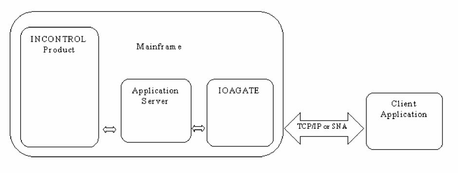
IOAGATE is a mainframe software communications gateway (middleware) that enables INCONTROL mainframe applications to communicate with other mainframe and non-mainframe applications over the network.
Client applications access INCONTROL products by means of an application server through IOAGATE.
Figure 47 Access of INCONTROL Products through IOAGATE
IOAGATE supports multiple concurrent application servers of different applications and their clients. A single IOAGATE can support
-
Control-O (specifically Control-O to Control-O connections)
-
Control-M JCL Verify monitor (CTJMON) (specifically CTJMON to CTJMON connections)
-
Control-M
-
Control-D (specifically Control-D/Page On Demand and Control-D/File Transfer Option)
IOAGATE allows one application to communicate with multiples of the same application.
-
Control-O can communicate with multiple other Control-Os by means of one IOAGATE connecting to multiple IOAGATEs sitting on other mainframes. CTJMON can communicate with other instances of CTJMON in the same manner.
-
Control-M/Enterprise Manager can communicate with Control-M.
-
Control-D/WebAccess Server can communicate through Control-D/Page On Demand to access the Control-D repositories through IOAGATE.
-
Control-D Session Agent can transfer files to Control-D on an MVS using IOAGATE and the Control-D/File Transfer Option application server.
IOAGATE can support multiple, dedicated or shared communication channels. A shared channel indicates that multiple applications use that same port or LU for their communication. A dedicated channel refers to a port or LU that is used exclusively by one application.
IOAGATE can periodically check the connection to the client when it is in a TCP/IP dual communications model. For an explanation of dual communications model, see Channel Sharing. When IOAGATE discovers broken connections, it closes them and listens for new ones.
In addition, IOAGATE can recover broken connections with clients. IOAGATE can recover failed application servers and subtasks as well.
IOAGATE distributes client requests to the next available application server through a sequential search of available application server address spaces.
Supporting Multiple Application Servers
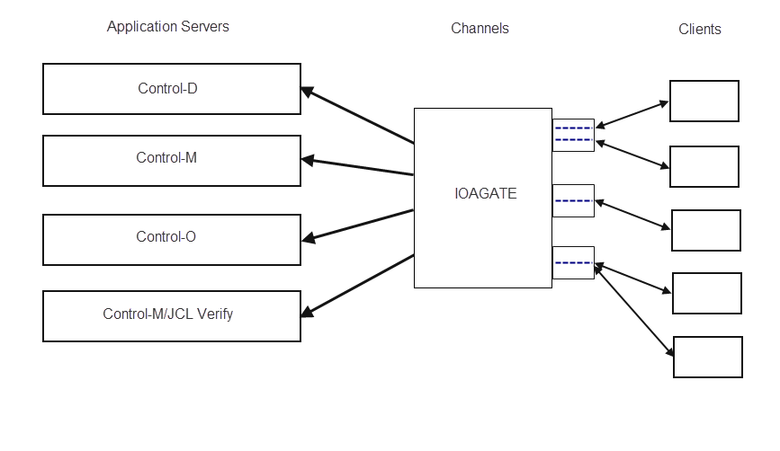
IOAGATE supports communication between multiple application servers and their clients.
The following example illustrates multiple INCONTROL applications communicating with multiple clients.
Figure 48 Multiple INCONTROL Applications Communicating with Multiple Clients
Channel Sharing
A channel consists of the following components:
-
Communications protocol (TCP/IP or SNA)
-
Communications model
A set of communication subtasks inside IOAGATE that interface with TCP/IP or VTAM according to the protocol and model
Specific applications use a specific communications model. A communications model refers to the type of connection that handles the multiple users’ requests. These connections may be either Dual Connection Channels or Multiple Connection Channels.
Dual Connection Channels (DC) are two connections that are multiplexed by the client application in order to handle a multitude of users. This model is used by Control‑M and Control‑M/Enterprise Manager. The first connection is dedicated for traffic from IOAGATE to the client application and the other connection is for traffic in the opposite direction.
Multiple Connection Channels (MC) use a single port or LU to establish all new connections, each of which then receives its own socket and/or conversation and communication traffic. Control‑D/Page On Demand, Control‑D/File Transfer Option, Control‑O, and Control‑M/JCL Verify use this type of connection.
One Multiple Connection Channel can be shared between different instances of the same application using Multiple Connection Channels with the same protocol. For example, multiple instances of Control-D/WebAccess could be configured to use the same channel.
Dedicated Channels
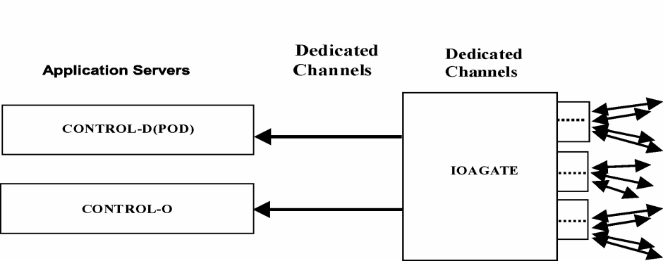
The simplest way to configure an IOAGATE channel is shared channel use. When a shared channel is overloaded, the IOAGATE channel can be configured for dedicated use by product. Congestion on a Multiple Connection TCP channel can also be relieved by assigning more communication subtasks to a channel. For more information, see "UPERTASK" in Specifying Advanced Channel Parameters.
The following example illustrates IOAGATE configured with dedicated channels:
Figure 49 IOAGATE Configured with Dedicated Channels
When using a dedicated channel configuration with IOAGATE
-
Control-D/Page On Demand may use either a TCP/IP or SNA protocol with a Multiple Connection Channel
-
Control-M and Control-M/Enterprise Manager must use a TCP/IP protocol with a Dual Connection Channel
-
Control-O may use either a TCP/IP or SNA protocol with a Multiple Connection Channel
-
Control-D/File Transfer Option must use a TCP/IP protocol with a dedicated Multiple Connection Channel
-
Control M/JCL Verify must use a TCP/IP protocol with a Multiple Connection Channel
Application Server Cloning
For Control‑D/Page On Demand and Control‑D/File Transfer Option applications, if an application server address space is overloaded, additional address spaces can be defined in additional APSERVER statements, to distribute the load. For more information, see Option 1, Application, for the Add function under Step 20.2 – Configure IOAGATE Parameters. Additional application server subtasks within an application server can also be defined, to relieve overload. For more information, see Option 1, Application, for the A (Advanced) function under Step 20.2 – Configure IOAGATE Parameters.
TCP/IP Requirements
The following describes customization requirements for configuring the communication between IOAGATE and client applications using the TCP/IP protocol.
TCP/IP on z/OS
-
z/OS IBM Communication server (CS)
-
SNS/TCPaccess v 5.3 or above from CA
Functional TCP/IP Connection
A functional TCP/IP connection is required between IOAGATE and the client application, that is,
-
Control-M/EM
-
Control-D/Page On Demand
-
Control-D Session Agent
-
IOAGATE (for Control-O to Control-O and for CTJMON to CTJMON connections)
Any network topology configuration that supports TCP/IP (hardware and software) can be used, as long as TCP/IP connections can be established between IOAGATE and the client application workstation. Connectivity should be verified before you start the client application, for example, by using the ping command, Telnet commands, or other TCP/IP applications to test.
Multiple Connection Channels Using SNA Session Support
This section describes how to establish parallel sessions between the following specific client applications:
-
Control-D/WebAccess Server and IOAGATE over Microsoft SNA Server
-
Control-O to Control-O and IOAGATE using IBM Communication Server for z/OS
SNA Server can also be configured to support single-session logical unit (LU) dependent connections to IOAGATE.
Enabling parallel sessions between the client applications and IOAGATE allows sessions to connect to their respective repositories through a single logical unit.
Note:The steps for mainframe-related configuration activities are provided in the following topic. For non-mainframe related steps, see the documentation of the relevant client application.
To support parallel sessions, the following components must be configured:
-
Mainframe (in VTAM and IOAGATE)
-
Microsoft SNA Server or Microsoft Host Integration Server 2000 or 2004
References to Microsoft SNA Server in the following section include Microsoft Host Integration Server 2000 and 2004.
Changes must be made in VTAM and IOAGATE to support parallel sessions.
Enabling Parallel Session Support:
This procedure describes how to enable parallel session support.
Begin
-
Verify independent logical unit support by verifying that the SNA connection supports XID format3, and that the node VTAMPU definition includes the XID=YES configuration.
The SNA server physical unit (PU) connection must support PU2.1.
To verify the XID type used by the SNA connection, do the following:
-
Open Microsoft SNA Server Manager.
-
Double-click the Connections tree node.
-
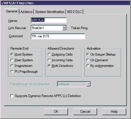
Right-click the connection used for the independent LU session and select Properties from the popup menu.
SWPU30 is used as an example connection name.
The Connection Properties dialog box is displayed.
Figure 50 Connection Properties: General Tab
Click the System Identification tab.
Figure 51 Connection Properties: System Identification Tab
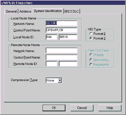
In the XID Type field, select Format3 and click OK.
-
-
Add a new LU called LUPRL to the SNA server node VTAM member and set LOCADDR to0 to configure the logical unit as independent.
CopySWPU30 PUADDR=01,
CPNAME=CPSWPU30,
PUTYPE=2,
XID=YES,
...
LUPRLLULOCADDR=0 -
Use INACT and ACT commands to initiate the new LU definition.
-
In SYS1.VTAMLST, create a new application Major Node for IOAGATE with parallel session support, or add the following definitions, which appear in the ECAMAPPL member in the SAMPLE library, to an existing member:
CopyVBUILD TYPE=APPL
PODLUP APPL AUTH=(VPACE),
DSESLIM=256,/* Max concurrent logged on users */
OPERCNOS=ALLOW,
APPC=YES,
VPACING=7Do not specify DLOGMODE or MODETAB.
The logical unit (LU) name PODLUP can be changed if you alter all references to it.
-
Activate the application major node. For an existing application major node, recycle the node using INACT and ACT commands.
When a new logical unit is defined, the DSESLIM takes effect immediately. When adding DSESLIM to an existing LU (and performing INACT and ACT), DSESLIM does not take effect immediately.
The following CNOS command can be used to set the parallel session limits to take effect immediately:
CopyF VTAM,CNOS,ID=PODLUP,LUNAME=LUPRL,LOGMODE=#INTER,LIMITS=(256,0,256)where PODLUP is the name of the remoteLU and LUPRL is the name of the localLU.
-
Specify the LUname to IOAGATE. Set the APPLID parameter to PODLUP in the ECAPARM member under the SNA multi-connection used for this connection.
Configuration of Microsoft SNA Server
Microsoft SNA Server can be configured to allow parallel sessions to connect to IOAGATE using SNA protocol. This is accomplished by defining a single logical unit that is shared by all users.
To configure Microsoft SNA, see the documentation of the relevant client application.
SNA Parameters Configuration Table
The following table shows how each element is configured to establish parallel sessions between the various client applications and IOAGATE over Microsoft SNA Server.
SNA Parameters
Table 169 SNA Parameters
|
Element |
Sample |
IOAGATE |
VTAM |
MS SNA Server |
Client Application |
|---|---|---|---|---|---|
|
Local LU Name |
LUPRL |
|
Independent LU name |
Local APPC LU name |
|
|
Remote LU name |
PODLUP |
Defined in ECAPARM member |
Application name |
Remote APPC LU name & Partner LU name |
|
|
CPIC Symbolic Name |
MSSNAP |
|
|
CPIC name |
CPIC Symbolic Destination |
|
Session Limit |
256 |
|
DSESLIM parameter & CNOS command |
Parallel session limit |
|
|
Mode name |
#INTER |
|
Defined in the IBM default Mode table |
APPC mode |
|
IOAGATE Recovery Considerations
IOAGATE supports the following recovery features:
This section describes how to implement these features with IOAGATE.
VIPA and DVIPA Support
This subsection describes IOAGATE support for the VIPA (Virtual IP Address) and DVIPA (Dynamic Virtual IP Address) features of the IBM OS/390 or z/OS Communications Server.
Unlike a regular IP address, which is associated with a specific communication adapter, a Virtual IP Address is not associated with a specific adapter and may be transferred from one z/OS image to another.
VIPA and DVIPA have the following flavors:
VIPA Takeover
The VIPA takeover feature associates an individual VIPA with a TCP/IP stack, allowing the VIPA to be moved from a failing z/OS image to a backup image. This is functionally similar to replacing a computer but keeping the same IP address. Using this feature, all applications that are moved to the backup image can be reached by the same IP address that they were associated with on the failed image.
If this method is used for IOAGATE recovery, IOAGATE should be restarted on the backup image which has taken over the VIPA address.
IOAGATE transparently supports VIPA takeover, and therefore no special definitions are required in IOAGATE to implement it.
Pure Dynamic VIPA for a Single Application Instance
The pure Dynamic VIPA (DVIPA) feature allows a VIPA to be associated with a particular application instance. Using this feature, when an application is moved to another z/OS host image in a Sysplex environment, the VIPA remains associated with that application.
If the application fails, the application can be restarted in another TCP/IP stack in the Sysplex environment. The VIPA associated with that application is automatically activated at the new stack when the application BINDs to it.
General Sysplex Environment Requirements
When using the pure DVIPA feature for IOAGATE recovery, you must configure your Sysplex environment as follows:
-
RUN a routing server OMPROUTE on each image in the Sysplex
The new location of the moved IPAddress must be advertised to routers in the network, so that reconnection requests are routed to the backup z/OS image. This requires running a Dynamic Routing Server (OMPROUTE) on both the original z/OS image, and the backup image.
-
DEFINE DVIPA support in the TCP/IP profile
To enable DVIPA support for an application, use the VIPARANGE statement in the TCP/IP profile to define the VIPA for each TCP/IP stack where the application may run.
For OS/390 version 2.8, the following example illustrates the syntax for VIPARANGE:
CopyVIPADYNAMIC
VIPARANGE DEFINE 255.255.255.0 172.16.240.193
ENDVIPADYNAMIC-
Create a local CA certificate called MYCA using the following command. Modify the command parameters to reflect the naming conventions used at the installation:
CopyRACDCERT CERTAUTH GENCERT SUBJECTSDN(CN('MYCA') O('BMC') C('US'))
KEYUSAGE(CERTSIGN) WITHLABEL('MYCA') -
Create a private/public key pair and a digital certificate using the following command. The local CA certificate, MYCA, is used for the digital certificate. Replace GATEUSER with the IOAGATE RACF user ID.
CopyRACDCERT ID(GATEUSER) GENCERT SUBJECTSDN(CN('IOAGATE') O('BMC')
C('US'))WITHLABEL('IOAGATE') SIGNWITH(CERTAUTH LABEL('MYCA'))
KEYUSAGE(HANDSHAKE) -
Assign the digital certificate a trusted status using the following command:
CopyRACDCERT ID(GATEUSER) ALTER (LABEL('IOAGATE')) TRUST -
Export the digital certificate using the following command:
CopyRACDCERT CERTAUTH EXPORT(LABEL('MYCA')) DSN('hlq.EXPORT.P12') -
Add the digital certificate to the client's key database using sslcmd or the Java keytool utility.
For OS/390 version 2.10 and later, the following example illustrates the syntax for VIPARANGE:
CopyVIPADYNAMIC
VIPARANGE DEFINE MOVEABLE NONDISRUPT 255.255.255.0 172.16.240.193
ENDVIPADYNAMIC -
IOAGATE Implementation
IOAGATE implements DVIPA support using the following channel parameter in the CHANNEL declaration in the ECAPARM member:
BIND={INADDR_ANY|IP_Address|Hostname}where
-
INADDR_ANY indicates that IOAGATE BINDS to any IPaddress, meaning that it listens to all adapters. Default.
-
IP_Address or Hostname indicates that IOAGATE BINDs to either the given IP_address or the IPaddress after Hostname resolution, respectively.
If the IP address as set in the BIND parameter is defined in the TCP/IP profile as an application-associated DVIPA, the specified IP address is associated with IOAGATE and "follows" IOAGATE when it "fails" on one image and restarts on the other image.
You can use the BIND parameter of the TCP/IP Profile PORT statement to define IOAGATE support for this feature transparently, meaning, without setting the BIND parameter in IOAGATE.
Considerations for Implementing DVIPA Support for IOAGATE with the Control-M Application Server (CTMAS)
When a z/OS image fails, Control‑M/Enterprise Manager running on either Unix or Windows NT detects the connection failure to IOAGATE through its keep-alive mechanism, and attempts to reconnect to IOAGATE. When IOAGATE and CTMAS are restarted on a backup image using the DVIPA associated with IOAGATE, Control‑M/Enterprise Manager will successfully reconnect to IOAGATE on the new image.
IOAGATE running in conjunction with the CTMAS can be moved to any z/OS image in a Sysplex without being tied to the z/OS image in which the main Control‑M Monitor is running. This is because CTMAS communicates with Control-M through files such as the Active Jobs file (AJF), IOA Conditions file, and Control‑M Resources file, as well as through Shouts and GRS (the ENQ/DEQ mechanism).
Although multiple IOAGATE instances can be started in parallel anywhere in a Sysplex to support other applications, only one instance of IOAGATE used in conjunction with CTMAS can exist in the Sysplex, using the CTMPLEX facility. For more information on CTMPLEX, see the Control‑M chapter in the INCONTROL for z/OS Administrator Guide.
Dynamic VIPA for Multiple Application Instances with the Sysplex Distributor
The IBM Communications Server enables you to run multiple instances of an application on multiple z/OS images, allowing the multiple application instances to share the same Dynamic Virtual IP Address. The Sysplex Distributor distributes connection requests from clients between the application instances based on predefined policies.
Sysplex Environment Requirements
Implement the Sysplex Distributor according to the appropriate IBM documentation.
The following example illustrates how to define the DVIPA address 172.16.240.193 as a distributed DVIPA under the control of the Sysplex Distributor.
This example does not constitute a complete example for implementing the Sysplex Distributor.
VIPADYNAMIC
                VIPARANGE DEFINE MOVEABLE NONDISRUPT 255.255.255.0 172.16.240.193
                VIPADISTRIBUTE DEFINE 172.16.240.193 PORT 4000 DESTIP ALL
            ENDVIPADYNAMIC
Considerations when using Control-D/Page On Demand for Control-D/WebAccess Support
The Sysplex Distributor is useful when using IOAGATE in conjunction with Control‑D/Page On Demand for support of Control‑D/WebAccess. Control‑D/WebAccess can potentially have thousands of users in one Sysplex. The Sysplex Distributor enables you to distribute the load between multiple z/OS images, providing scalability, load balancing, and availability.
When you use the Sysplex Distributor with Control-D/WebAccess, define the following channel parameter in the CHANNEL declaration in the ECAPARM member:
BIND=DVIPA_addressUsing the example as described in Sysplex Environment Requirements, the corresponding definitions for that example would be:
PORT=4000,
            BIND=172.16.240.193
You can use the BIND parameter of the TCP/IP Profile PORT statement to define IOAGATE support for this feature transparently, meaning, without setting the BIND parameter in IOAGATE.
Automatic Restart Management Support
Automatic restart management can reduce the impact of an unexpected error to a system program by restarting it automatically, without operator intervention. In a Sysplex environment, a system program can enhance its own recovery potential by registering as an element of the automatic restart management function of the cross system coupling facility (XCF).
To provide program recovery through automatic restart management, your installation must activate a policy through the SETXCF START command. This can be an installation-written policy or part of the IBM-supplied policy defaults. Because an installation-written policy may affect your program, you must understand how your installation uses automatic restart management for recovery in a Sysplex. Details of the automatic restart management function are described in the section of IBM publication OS/390 MVS Sysplex Services Guide that discusses using the automatic restart management function of XCF.
In general, the operating system restarts an element under the following conditions:
-
when the element itself fails—in this case, the operating system restarts the element on the same system
-
when the system on which the element was running unexpectedly fails or leaves the Sysplex—in this case, the operating system restarts the element on another system in the Sysplex. This is called a cross-system restart.
The operating system will not attempt to restart an element if
-
the element has not yet registered as an element of automatic restart management
-
the element is cancelled through a CANCEL, STOP, or FORCE command (without the ARMRESTART parameter specified)
-
JES is down or has indicated that the element should not be restarted
-
the element has reached the restart attempts threshold specified in the policy
-
the policy indicates that this element should not to be restarted
-
access to the ARM couple data set was lost
Installing and Implementing Automatic Restart Management for IOAGATE
-
Follow the instructions to set up an automatic restart management policy as specified in the section of IBM publication z/OS V1Rx MVS Setting Up a Sysplex that discusses automatic restart management parameters for administrative data utility. Some of the restart parameters are discussed in Restart Parameters.
Your system does not need to specify an automatic restart management policy if the default values are acceptable. The default values, if any, are described under each parameter in IBM publication z/OS V1Rx MVS Setting Up a Sysplex, in the section discussing automatic restart management parameters for administrative data utility.
-
Specify the IOAGATE ARMELEM parameter in the ECAPARM member as described in Step 20 – Install IOAGATE (Optional).
-
Stop and then restart the IOAGATE monitor. At restart, IOAGATE checks the ARMELEM parameter in ECAPARM and, if specified, registers as an element of automatic restart management. The IOAGATE monitor then issues the following message:
CopyECAG0HI ENABLED FOR THE AUTOMATIC RESTART MANAGEMENT FUNCTIONIf IOAGATE fails to activate ARM when starting up, it issues the following message:
CopyECAG0JW AUTOMATIC RESTART MANAGEMENT REQUEST FAILED R15=XX REASON=XXXX
Automatic Restart Management and IOAGATE Failure
If ARM support is enabled and IOAGATE fails unexpectedly, the following message is issued when the operating system automatically restarts IOAGATE:
ECAG0II AUTOMATIC RESTART IN PROGRESS AFTER UNEXPECTED FAILURERestart Parameters
There are several ARM policy parameters you can choose to determine where, under what circumstances, and how many times, IOAGATE is to be restarted. Some of these restart parameters are described in the following table.
Table 170 Restart Parameters
|
Parameter |
Description |
|---|---|
|
TARGET_SYSTEM |
Systems on which IOAGATE can be restarted in a cross-system restart. |
|
ELEMENT |
Element name that represents IOAGATE. This must exactly match the ARMELEM ECAPARM parameter. |
|
RESTART_ATTEMPTS |
Maximum number of times that the operating system should attempt to restart IOAGATE. This limit prevents the operating system from continually restarting an element that is recursively terminating. |
|
TERMTYPE |
Specifies under which condition the operating system should restart IOAGATE. Valid values are:
|
|
RESTART_METHOD |
Specifies the command text that the operating system is to use to restart the element. RESTART_METHOD. (BOTH,PERSIST) indicates that the operating system is to use the command text that previously started IOAGATE. |
To obtain information about elements of the automatic restart manager while the system is active, you can issue the D XCF,ARMSTATUS,DETAIL MVS operator command. For more information about this command, see the discussion about displaying cross system coupling facility (XCF) information, in the IBM publication MVS System Commands.
The following is an example of an addition to the existing automatic restart management policy of an installation. The example specifies a target system and directs that IOAGATE should be restarted only if the system program terminates, but not when the system terminates.
RESTART_GROUP(IOAGATE)
                    TARGET_SYSTEM(OS35)
                    ELEMENT(IOAGATE)
                TERMTYPE(ELEMTERM)
SSL Support
SSL is available for providing secure communication for IOAGATE. Procedures for implementing SSL are described in this section (refer to the following table). The steps required for implementing SSL can be performed on the mainframe, externally, or partially on the mainframe and partially externally. You can use Control‑M Configuration Manager for implementing SSL, as described in detailed in the Control-M SSL Guide.
SSL encryption is not supported in the communication between the Control-M JCL Verify monitors or between Control-O monitors.
Table 171 Various SSL Operations for INCONTROL Components
|
Operation |
|---|
|
Creating Keys and Certificates for IOAGATE for Use with Control-M and Control-D |
IOAGATE supports Security Access Facility (SAF) (for example, RACF) as the key database. Various settings for IOAGATE and the corresponding SSL security levels are indicated in the following table.
Table 172 SSL Security Levels Supported by IOAGATE
|
SSL support level |
Setting in the ECAPARM |
Keys |
CA Certificate |
|---|---|---|---|
|
None |
SSL=No |
N/A |
N/A |
|
Server (IOAGATE) authentication only |
SSL=Yes CLIAUTH=No (Default when SSL=Yes) |
IOAGATE requires a private/public key pair and a certificate signed by a CA. This certificate must be defined in SAF and added to the keyring defined for IOAGATE by the KEYRING parameter in the ECAPARM member. |
The certificate of the CA that has signed IOAGATE's certificate must be added to the key database on the peer side using sslcmd or the Java keytool utility. |
|
Both Server (IOAGATE) and Client authentication |
SSL=Yes CLIAUTH=Yes |
In addition to the IOAGATE’s keys, the client must have a private/public key pair and a certificate signed by a CA. These items must be added to the client’s local key database. |
In addition to the signed IOAGATE certificate, the certificate of the CA, which signed the client's certificate, must be added to the keyring defined for IOAGATE by the KEYRING parameter in the ECAPARM member. |
The following commands allow access to the RACF RACDCERT command by user ID admin:
-
RDEFINE FACILITY IRR.DIGTCERT.* UACC(NONE)
-
PERMIT IRR.DIGTCERT.* CLASS(FACILITY) ID(admin) ACCESS(Control)
-
SETROPTS RACLIST(FACILITY) REFRESH
Control-D/Agent client 3.7.00 (or later) can transfer files to Control-D on an MVS using IOAGATE and the Control-D/File Transfer Option application server.
For a background on SSL refer to the internet. For documentation of SSL support by Control-M/EM and Control-M Configuration Manager, refer to the Control-M SSL Guide. For documentation of SSL support by Control-D/Agent client refer to Control‑D/Agent User Guide version 3.7.00 (or later).
Creating Keys and Certificates for IOAGATE for Use with Control-M and Control-D
Key pairs and certificates can be created for IOAGATE by using a SAF on the mainframe or an external CA, or with a combination of these two approaches. These keys and certificates can be used for communication with Control-M or Control-D. See the following table for the method appropriate to your site.
Table 173 Alternate Methods of Generating and Signing IOAGATE Keys and Certificates
|
Keys generated by: |
CA |
See page |
|---|---|---|
|
RACF |
RACF |
Using the Basic Methods: RACF or Control-M Configuration Manager |
|
Control-M Configuration Manager |
Control-M Configuration |
|
|
RACF |
External CA |
|
|
outside mainframe |
Outside mainframe |
|
|
"Bring Your Own" (Control-M Configuration Manager) |
External CA |
Using the Basic Methods: RACF or Control-M Configuration Manager |
Table 174 Additional Operations
|
To: |
See page |
|---|---|
|
add keyring |
|
|
add client authentication |
Using the Basic Methods: RACF or Control-M Configuration Manager
In this section, the procedures using RACF (an example of SAF) and Control-M Configuration Manager are described.
This procedure describes how to create keys and certificates using RACF.
Begin
Generating Certificates with Control-M/EM or "Bring Your Own"
This procedure describes how to generate certificates with Control-M/EM or "Bring Your Own".
Begin
When keys and certificates are generated externally and brought to Control-M/EM for distribution ("Bring Your Own (BYO)" ), the certificates are placed in the same folder as if generated by Control-M/EM.
For use of keys and certificates with Control-D, use the BYO method.
If BYO is used, skip steps 1 & 2, refer to step 3 and continue from step 4.
-
In the Control-M Configuration Manager, choose Tools => System Configuration=> Control-M/EM System Parameters=> Advanced=> CmsCommMode
-
Set the CmsCommMode parameter to auto.
-
In the Control-M Configuration Manager, choose Tools => Security=> Manage SSL=> Generate Component Certificates...
Two certificates (files) are generated in the Certificate_for Control-M_for_zOS folder.
For Control-D/WebAcess Server, ready-made certificates can be found here:
<Installation Path>/config/ssl/ioagte.-
IOAGATE.PCK12
This is the certificate which includes the private/public key pair of IOAGATE. This file is encrypted with a password that can be found in the README file created by Control-M/EM or provided in Control-D.
-
CACERT.PEM
This is the certificate of the CA (Control-M/EM or Control-D) itself that is needed for decrypting IOAGATE.PCK12. If client authentication is required, this certificate is also the certificate of the CA that signed the certificate of the client.
-
-
FTP IOAGATE.PCK12 to z/OS in binary mode. Assume that the file name on z/OS is IOAGATE.PCK12.
By default, FTP allocates the new file with the following attributes:
-
Organization: PS
-
Record format: VB
-
Record length: 256
-
Block size: 6233
-
-
FTP CACERT.PEM to z/OS in ASCII (text) mode. Assume that the file name on z/OS is CACERT.PEM.
By default, FTP allocates the new file with the following attributes:
-
Organization: PS
-
Record format: VB
-
Record length: 256
-
Block size: 6233
-
-
Import CACERT.PEM to RACF using the following command:
CopyRACDCERT CERTAUTH ADD ('CACERT.PEM') WITHLABEL('CACERTXX')Choose XX so that the name is unique and does not conflict with an existing name.
-
Create IOAGATERING (if it does not already exist) with the following command:
CopyRACDCERT ID(GATEUSER) ADDRING(IOAGATERING) -
Connect CACERTXX to IOAGATERING with the command:
CopyRACDCERT ID(GATEUSER) CONNECT(CERTAUTH LABEL('CACERTXX')
RING(IOAGATERING)) -
Import IOAGATE's certificate with the command:
CopyRACDCERT ID(GATEUSER) ADD('IOAGATE.PCK12') TRUST WITHLABEL('IOAGATEXX')
PASSWORD('ctm_zos_hhmm')The hhmm part of the password can be found in the README file generated by Control-M/EM.
-
Connect IOAGATEXX to IOAGATERING with the command
CopyRACDCERT ID(GATEUSER) CONNECT(ID(GATEUSER) LABEL('IOAGATEXX')
RING(IOAGATERING) DEFAULT USAGE(PERSONAL)) -
For connecting to Control-M Configuration Manager and to Control-M/EM, define the following in ECAPARMC and in ECAPARMM CHANNELs:
-
SSL=YES
-
KEYRING=IOAGATERING
-
KEYRLAB=IOAGATEXX
If client authentication is needed, also specify:
-
CLIAUTH=YES
Both IOAGATEC and IOAGATEM must have the same SSL definitions.
-
-
Stop and restart IOAGATEM and IOAGATEC.
For more information about the CmsCommMode parameter, see the "Control-M/EM" sub-section in the "SSL communication parameters" section in the "Preparing to use SSL" chapter in the Control-M SSL Guide.
For more information about generating the certificates in Control-M/EM, see the "Generating component certificates using the wizard" section in the "Managing certificates" chapter in the Control-M SSL Guide.
Using Variations of the Basic Methods
Key pairs and certificates can either be created for IOAGATE by using RACF on the mainframe and then certified with an external CA or they can be generated outside the mainframe and then imported to the mainframe. These procedures are described in this section.
Certifying Keys Created with RACF Using an External CA
This procedure describes how to certify keys created with RACF using an external CA.
Begin
-
Define a local CA certificate and a digital certificate for IOAGATE as described in the first steps of the following procedure: "To create keys and certificates using RACF" in Using the Basic Methods: RACF or Control-M Configuration Managers.
-
Generate a certificate request for IOAGATE, using following command:
CopyRACDCERT ID(GATEUSER) GENREQ (LABEL('IOAGATE')) DSN('hlq.GENREQ')The GENREQ command generates a certificate request in PKCS#10 format, based on an existing certificate with a private key and writes it to hlq.GENREQ.
-
Send the resulting file to a CA for signing. The reply from the CA contains the signed certificate.
-
FTP (in ASCII mode) the reply from the CA to the mainframe, replacing the IOAGATE certificate.
The following command assumes that the certificate has been uploaded into the hlq.NEWCERT.PEM data set:
CopyRACDCERT ID(GATEUSER) ADD('hlq.NEWCERT.PEM') TRUST WITHLABEL('IOAGATE')
Creating Keys and Certificates Manually, and Importing them into the Mainframe
This procedure describes how to create keys and certificates externally, and then import them into the mainframe.
Begin
-
Generate and export the certificate to be used by IOAGATE including the private key in PKCS#12 format.
The exact generation and export process depends on the platform and tool being used, and is not described here. The export process will request a password for encrypting the generated file. This password is needed in the next step.
-
FTP (in ASCII mode) the certificate of the CA, which signed the IOAGATE’s keys and certificates, to the mainframe and import it:
CopyRACDCERT CERTAUTH ADD('hlq.CACERT1.PEM') WITHLABEL('CACERT1') -
FTP the PKCS#12 file to the mainframe to a sequential file and import it:
The PKCS#12 file must be transferred either in binary or in ASCII format, depending on the exact encoding of the PKCS#12 file. If the file is encoded using Base64 then it must be transferred in ASCII mode. Determine the required transfer mode by examining the first line. If the first line is "-----BEGIN CERTIFICATE-----", use ASCII format. Otherwise use binary format.
The following assumes that the file has been uploaded to the 'hlq.GATECERT.P12' data set and that it has been encrypted with the password abcd1234:
CopyRACDCERT ID(GATEUSER) ADD('hlq.GATECERT.P12') TRUST WITHLABEL('IOAGATE')
PASSWORD('abcd1234')
Regardless of which of the above methods is used, the following procedures are required.
Creating a Keyring
This procedure describes how to create a keyring.
Begin
-
Create the RACF keyring for IOAGATE.
The following command creates a keyring named IOAGATERING for user ID GATEUSER:
CopyRACDCERT ID(GATEUSER) ADDRING(IOAGATERING) -
Connect IOAGATE’s certificate to the keyring.
The certificate containing the private key used for decryption must be connected to the user's keyring as the default certificate:
CopyRACDCERT ID(GATEUSER) CONNECT(ID(GATEUSER)
LABEL('IOAGATE') RING(IOAGATERING) DEFAULT USAGE(PERSONAL)) -
Connect CA’s certificate to the keyring.
CopyRACDCERT ID(GATEUSER) CONNECT(CERTAUTH
LABEL('CACERT1') RING(IOAGATERING)
Adding Client Authentication
This procedure describes how to add client authentication.
Begin
-
FTP (in ASCII mode) the CA's certificate to the mainframe and import it:
CopyRACDCERT CERTAUTH ADD('hlq.CACERT.PEM') WITHLABEL('CACERT') -
Connect the CA's certificate to IOAGATE's keyring:
CopyRACDCERT ID(GATEUSER) CONNECT(CERTAUTH LABEL('CACERT') RING(IOAGATERING))
Using Demo Certificates for IOAGATE with Control-M
For testing SSL functionality between IOAGATE and Control-M/EM and Control-M Configuration Manager, install the demo certificates provided by Control‑M/EM and by IOA.
The sample certificates are for demonstration purposes only and must not be used in a production environment.
The following sample members are provided with the IOA installation in the SAMPLE library:
-
CERTGATE - Demo certificate for IOAGATE, including a private/public key pair signed by the demo certificate authority that is included in the demo key database of Control-M/EM and Control-M Configuration Manager.
-
CERTCA - Demo certificate of the above demo certificate authority.
-
CERTCOPY - Sample job for copying the demo certificates to a sequential variable blocked (VB) file.
Enabling SSL on the Control-M/EM Side
This procedure describes how to enable SSL on the Control-M/EM side.
Begin
-
In the Control-M Configuration Manager, choose Tools => System Configuration=> Control-M/EM System Parameters=> Advanced=> CmsCommMode
-
Set the CmsCommMode parameter to auto.
For more information about the CmsCommMode parameter, see the "Control‑M/EM" sub-section in the "SSL communication parameters" section in the "Preparing to use SSL" chapter in the Control-M SSL Guide.
Enabling SSL on the INCONTROL Side
This procedure descrbies how to enable SSL on the INCONTROL side.
Begin
-
Copy the CERTCA and CERTGATE sample members to sequential files using the CERTCOPY sample job.
This step is needed because RACDCERT must be provided with the demo certificates in a sequential VB file.
The SAMPLE job CERTCOPY is listed below:
Copy//COPYCERT JOB (ACCOUNT),'PGMR',NOTIFY=&SYSUID
//IEBGENER EXEC PGM=IEBGENER
//SYSPRINT DD SYSOUT=*
//SYSUT1 DD DISP=SHR,DSN=IOAP.V900.SAMPLE(CERTCA)
//SYSUT2 DD DISP=(,CATLG),DSN=IOA.CERTCA.DEMO
// RECFM=VB,LRECL=84,BLKSIZE=27998,
// UNIT=3390,SPACE=(TRK,(1,1))
//SYSIN DD DUMMY
//*
//IEBGENER EXEC PGM=IEBGENER
//SYSPRINT DD SYSOUT=*
//SYSUT1 DD DISP=SHR,DSN=IOAP.V900.SAMPLE(CERTGATE)
//SYSUT2 DD DISP=(,CATLG),DSN=IOA.CERTGATE.DEMO
// RECFM=VB,LRECL=84,BLKSIZE=27998,
// UNIT=3390,SPACE=(TRK,(1,1))
//SYSIN DD DUMMY -
Import the CA certificate:
CopyRACDCERT CERTAUTH ADD('IOA.CERTCA.DEMO') TRUST WITHLABEL('CACERT') -
Import IOAGATE's certificate:
GATEUSER is assumed to be the RACF USERID of IOAGATE. Replace all occurrences of GATEUSER in the sample commands below with the actual IOAGATE user ID.
CopyRACDCERT ID(GATEUSER) ADD('IOA.CERTGATE.DEMO') TRUST WITHLABEL('IOAGATE')
PASSWORD('abcd1234') -
Define a key ring for IOAGATE:
CopyRACDCERT ID(GATEUSER) ADDRING(IOAGATERING) -
Connect the certificates to IOAGATE's keyring:
CopyRACDCERT ID(GATEUSER) CONNECT(CERTAUTH LABEL('CACERT')
RING(IOAGATERING)USAGE(CERTAUTH))
RACDCERT ID(GATEUSER) CONNECT(ID(GATEUSER) LABEL('IOAGATE')
RING(IOAGATERING))
Using Non-demo Certificates for IOAGATE with Control-D
This procedure describes how to use non-demo certificates for Control-D/WebAccess Server, or Control-D/File Transfer Option (FTO), from the distributed systems side.
These steps are for illustrational purposes only.
Begin
-
Create a key pair for your server and a digital certificate contained in the ctdagent.keystore file.
keytool -genkey -alias ctdagent –keyalg RSA -keystore keystore_file_path -storepass
keystore_password -keypass keystore_password -dname distinquished_name
The password for storepass and keypass must be identical.
Where distinquished_name (X.509 attributes of the certificate) are:
-
Common name (CN): Control-D_Agent
-
Country name (C): IL
-
State (ST): NotApplicable
-
Locality (L): NotApplicable
-
Organization (O): bmc
-
Organization Unit (OU): DBA
Copykeytool -genkey -alias ctdagent -keyalg RSA -keystore ctdagent.keystore1
storepass sarina -keypass sarina -dname "C=IL, CN=Control-D_Agent,
ST=NotApplicable, L=NotApplicable, O=BMC, OU=DBA" -
-
Generate a certificate signing request (CSR).
-
Run the following keytool utility to export a CSR from the keystore in order to sign it:
keytool -certreq -alias ctdagent -keystore keystore_file_path –storepass keystore_password -file certfilename.crs
Copykeytool -certreq -alias ctdagent -keyalg RSA -keystore ctdagent.keystore1
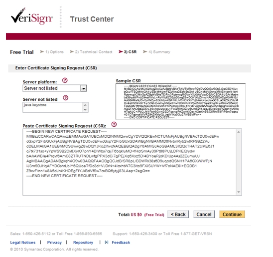
-storepass sarina -file ctdagentCerttest.crsUse a private or commercial trusted CA to sign the certificate. In the following sample we will connect to VeriSign http://www.verisign.com/ to get a trial certificate.
The CSR you have previously generated is a string of text generated by your server. Provide this string to VeriSign during the enrollment process.
When enrolling for your certificate, you will be prompted to select a server platform. In our case, select Server not listed and type Java keystore.
Figure 52 VeriSign Trust Center
-
You will receive the trial SSL certificate by mail.
Perform the instructions described in the mail that you receive.
-
-
Install the CA certificates:
Install the Trail Root CA and the Trail Intermediate CA certificate on the server’s keystore.
Download the root CA certificate from the link that you receive by mail and save it with the following name: rootCA.cer
Download the intermediate CA certificate from the link and save it with the following name: intermediateCA.cer
-
Import the root CA certificate and the intermediate CA certificate:
-
Import the root CA to your keystore file with the following command:
keytool –import –alias RootCA –keystore <your_keystore_filename> -trustcacerts –file rootCA.cer
Copy> keytool -import -alias RootCA -keystore ctdagent.keystore1 -file
rootCA.cer -trustcacerts
Enter keystore password: tsarina
Owner: CN=VeriSign Trial Secure Server Root CA - G2, OU="For Test Purposes
Only. No assurances.", O="VeriSign, Inc.", C=US
Issuer: CN=VeriSign Trial Secure Server Root CA - G2, OU="For Test Purposes
Only. No assurances.", O="VeriSign, Inc.", C=US
Serial number: 168164a428ca12dfab12f19fb1b93554
Valid from: 4/1/09 3:00 AM until: 4/1/29 2:59 AM
Certificate fingerprints:
MD5: E0:19:F5:FC:C0:9A:13:0E:38:B7:BF:0D:02:40:D3:C2
SHA1: 51:51:B8:63:8A:4C:1F:15:54:56:ED:37:C9:10:35:CA:D3:01:B9:36
Trust this certificate? [no]: yes
Certificate was added to keystore -
Import your intermediate CA certificate to your keystore file with the following command:
keytool –import –alias IntermediateCA –keystore <your_keystore_filename> -trustcacerts –file intermediateCA.cer
-
-
Install the trail SSL certificate:
Copy the certificate from your mail and paste it into a text file using notepad or vi.
Enter the following command to import your trail SSL certificate:
keytool –import –alias <your_aliasname> –keystore <your_keystore_filename> -trustcacerts –file <your_certificate_filename.DER>
The alias name in this command must be the same as the alias name used during the generation of the private key and CSR. The signed certificate must be in X.509 DER (Definite Encoding Rule) format.
Copykeytool -import -alias ctdagent -keystore ctdagent.keystore1 -file
signedcert.der -trustcacerts -
Configure the ctdagent.ssl.properties file and change your keystore password
-
Update parameter: KeystoreFile=ctdagent.keystore1
-
Change the encrypted KeystorePassword:
-
Run bmc-ctd-ssl-changepass (UNIX) or ctd-ssl-changepass.bat (Windows) from the <INSTALLATION PATH>/bin directory.
-
Enter a new password at the prompt to update the ctdagent.ssl.properties configuration file.
-
-
-
Recycle the Control-D/Agent file transfer server service.
Using Non-demo Certificates for Control-D, from the Mainframe Systems Side
This procedure describes how to use non-demo certificates for Control-D, from the mainframe systems side.
The following sample illustrates server (IOAGATE) authentication only.
Before You Begin
This level is specified by setting SSL=Yes and CLIAUTH=No (the default when SSL=Yes) in the ECAPARM member.
The following certificates must be in place for this support:
-
IOAGATE must have a certificate representing a private/public key and signed by a CA. This certificate must be defined in SAF (for example, RACF) and added to the keyring defined for IOAGATE by the KEYRING parameter in the ECAPARM member.
-
The certificate of the CA that has signed IOAGATE's certificate must be added to the key database on the peer side.
The following sample flow illustrates IOAGATE’s keys generated by RACF and signed by certificate authority outside the mainframe. In our example, we use the VeriSign site.
Begin
-
Define a local certificate authority and a digital certificate for IOAGATE
-
Generate a local Certificate Authority
CopyRACDCERT CERTAUTH GENCERT SUBJECTSDN(CN('Control-D_Agent') O('BMC')
C('IL') L(‘NotApplicable’) SP(‘NotApplicable’)) KEYUSAGE(CERTSIGN)
WITHLABEL('GATECA') -
Generate a Digital Certificate with a Private Key for IOAGATE
A digital certificate with a private key must be generated for the IOAGATE user.
CopyRACDCERT ID(STCUSER) GENCERT SUBJECTSDN(CN(' Control-D_Agent')
O('BMC') C('IL') L('NotApplicable')
SP('NotApplicable'))WITHLABEL('IOAGATE') SIGNWITH(CERTAUTH
LABEL('GATECA')) KEYUSAGE(HANDSHAKE) -
The RACDCERT ALTER command is required to add the TRUST attribute to the certificate:
CopyRACDCERT ID(STCUSER) ALTER (LABEL('IOAGATE')) TRUST
-
-
Generate a certificate request (CSR) for IOAGATE
The following command will generate a certificate request and write it to hlq.GENREQ:
CopyRACDCERT ID(STCUSER) GENREQ (LABEL('IOAGATES')) DSN('ilprefa.GENREQ') -
Send the CSR file to a certificate authority for signing.
-
FTP (in ASCII mode) the reply containing the signed certificate to the mainframe, and import it as IOAGATE’s certificate.
The following command assumes that the certificate has been uploaded into data set hlq.NEWCERT.PEM:
CopyRACDCERT ID(STCUSER) ADD('IOAQ.Q71MN.NEWCERT.PEM') TRUST WITHLABEL('IOAGATES') -
FTP (in ASCII mode) the certificate authority's certificate to the mainframe and import it:
You will receive a mail from Verisign. Install the intermediate certificate according to the mail. The following commands import the intermediate certificate:
CopyRACDCERT CERTAUTH ADD('ilprefa.CACERT.PEM') WITHLABEL('CACERTV') -
Connect the certificates to IOAGATE’s keyring.
CopyRACDCERT ID(STCUSER) CONNECT(CERTAUTH LABEL('CACERTV')
RING(IOAGATERING)USAGE(CERTAUTH))
RACDCERT ID(STCUSER) CONNECT(ID(GATEUSER)
LABEL('IOAGATES')RING(IOAGATERING)) -
Recycle IOAGATE and application server.
Using Demo Certificates for IOAGATE with Control-D
For Control-D/File Transfer Option (FTO), Control-D/Agent provides a DEMO certificate signed by the DEMO CA of Control D . The Control-D for z/OS is also signed by the same DEMO CA.
For SSL setup for Control-D/WebAccess Server, verify that you have already obtained the keys and certificates using the Generating Certificates with Control-M/EM or "Bring Your Own".
The sample certificates are for demonstration purposes only and must not be used in a production environment.
Enabling SSL on the Control-D/Agent File Transfer Server
This procedure describes how to enable SSL on the Control-D/Agent file transfer server.
Begin
-
In the configuration file, sesmgr.config, <INSTALLATION PATH>/config, set SSL true to enable the server to listen in SSL mode on the port.
-
Restart Control-D/Agent file transfer server.
Enabling SSL on the Control-D/Agent File Transfer Client
This procedure describes how to enable SSL on the Control-D/Agent file transfer server.
Begin
The -ssl command line parameter should be added to the command line to communicate with the host using SSL.
bmc-ctd-sftclient -h=host -p=port -u -f=input_file -d=output -sslThe Control-D file transfer client can send files to Control-D on z/OS via IOAGATE when IOAGATE is configured for Control-D/File Transfer Option support.
Setting Up the Control-D/File Transfer Option or the Control-D/WebAccess Server in IOAGATE for SSL
This procedure describes how to set up the Control-D/File Transfer Option or the Control-D/WebAccess Server in IOAGATE for SSL.
Begin
-
Specify the following parameters in ECAPARM:
CopySSL=YES,
KEYRING=<IOAGATE's keyring>,
KEYRLAB=<IOAGATE's certificate label>,
CLIAUTH=NO | YES,
SSL=YES,
KEYRING=IOAGATERING,
KEYRLAB=IOAGATEF,
CLIAUTH=NO, -
Use the following members in the SAMPLE library:
-
CERTGATF - DEMO Certificate for IOAGATE with private-public key pair signed by the DEMO certificate authority
-
CERTCAF - DEMO Certificate of the CA with its public key
-
CERTFTOF - Sample job to convert certificates to files that can be used as input to RACDCERT
-
-
Copy SAMPLE members CERTCAF and CERTGATF to sequential files using sample job CERTFTOF.
This step is needed because RACSCERT must be provided with the demo certificates in a sequential VB file, with trailing blanks removed.
Assume that these files will be called IOAQ.Q71MN.CERTCAF.DEMO and IOAQ.Q71MN.CERTGATF.DEMO.
Copy//Q53CER JOB ,OR,CLASS=A,MSGCLASS=X,REGION=0M,NOTIFY=&SYSUID
//*
//*
// JCLLIB ORDER=IOAQ.Q71MN.PROCLIB
// INCLUDE MEMBER=IOASET
//COPY1 EXEC PGM=SORT
//SYSOUT DD SYSOUT=*
//SORTIN DD DSN=IOAQ.Q71MN.SAMPLE(CERTCAF),DISP=SHR
//VBOUT DD DSN=IOAQ.Q71MN.CERTCAF.DEMO,
// DISP=(NEW,CATLG,DELETE),
// SPACE=(TRK,(1,1),RLSE),
// VOL=SER=IOAQ31,UNIT=3390,
// DCB=(RECFM=VB,LRECL=68,BLKSIZE=6800)
//SYSIN DD *
OPTION COPY
OUTFIL FNAMES=VBOUT,FTOV,VLTRIM=X'40'
/*
//COPY2 EXEC PGM=SORT
//SYSOUT DD SYSOUT=*
//SORTIN DD DSN=IOAQ.Q71MN.SAMPLE(CERTGATF),DISP=SHR
//VBOUT DD DSN=IOAQ.Q71MN.CERTGATF.DEMO,
// DISP=(NEW,CATLG,DELETE),
// SPACE=(TRK,(1,1),RLSE),
// VOL=SER=IOAQ31,UNIT=3390,
// DCB=(RECFM=VB,LRECL=68,BLKSIZE=6800)
//SYSIN DD *
OPTION COPY
OUTFIL FNAMES=VBOUT,FTOV,VLTRIM=X'40'
/* -
Go to RACF and issue the following RACF commands:
-
Import the CA certificate:
CopyRACDCERT CERTAUTH ADD('IOAQ.Q71MN.CERTCAF.DEMO') TRUST
WITHLABEL('CACERTF') -
Import IOAGATE's certificate:
CopyRACDCERT ID(STCUSER) ADD('IOAQ.Q71MN.CERTGATF.DEMO') TRUST
WITHLABEL('IOAGATEF') PASSWORD('abcd1234') -
Define a key ring for IOAGATE:
CopyRACDCERT ID(STCUSER) ADDRING(IOAGATERING) -
Connect the certificates to IOAGE's keyring:
CopyRACDCERT ID(STCUSER) CONNECT(CERTAUTH LABEL('CACERTF')
RING(IOAGATERING) USAGE(CERTAUTH))
RACDCERT ID(STCUSER) CONNECT(ID(STCUSER) LABEL('IOAGATEF')
RING(IOAGATERING))RING according to KEYRING defined in ECAPARM.
-
Recycle IOAGATE and the application server of Control-D/File Transfer Option.
-
Useful RACF Commands
The command:
RACDCERT ID(STCUSER) LISTRING(IOAGATERING)shows the following (sample):
Digital ring information for user STCUSER:

 Ring:
      >IOAGATERING<
 Certificate Label Name             Cert Owner     USAGE      DEFAULT
 --------------------------------   ------------   --------   -------
 CACERT15                           CERTAUTH       CERTAUTH     NO
 IOAGATED0112                       ID(STCUSER)    PERSONAL     YES
The command:
RACDCERT ID(STCUSER) LISTshows the following (sample):
 Label: IOAGATED0112
   Certificate ID: 2Qfi48Pk4sXZydbBx8HjxcTw8fHy
   Status: TRUST
   Start Date: 2009/12/01 15:12:26
   End Date:   2029/11/26 15:12:26
   Serial Number:
        >00F844CEEA5CB9AD20<
   Issuer's Name:
        >[email protected]=A.OU=Tzahi.O=Efrat.L=Nir.SP=kuku.C=IL<
   Subject's Name:
      >[email protected]=CONTROL-M for z/OS.OU=CONTROL-MaD.O=BMC <
      >Software Ltd..L=Tel-Aviv.SP=NA.C=IL<
   Private Key Type: Non-ICSF
   Private Key Size: 1024
   Ring Associations:
     Ring Owner: STCUSER
     Ring:
        >IOAGATERING<
Validation of an Incoming IP Address
This feature enables you to validate incoming IP addresses against a table in the ECAIPLSx member in IOA.PARM library. This list of IP addresses is a source table that contains IP addresses that are allowed or forbidden to communicate with IOAGATE. All incoming addresses are checked against the table.
Define these IP addresses using one of the following methods:
When IPv6 is enabled on the z/OS system, IOAGATE messages display incoming IPv4 connections in the form of IPv4-mapped IPv6 addresses. However, do not use IPv4-mapped IPv6 addresses in the ECAIPLSx member. Use the IPv4 addresses instead. IPv6 addresses can be specified in full (39 characters) or abbreviated format (for example, 'fd66:bc12:ac12:101::3'.
-
Defining specific IP addresses. For IPv4 addresses, these entries define the implicit subnet mask, 255.255.255.255
-
For IPv4 addresses, defining the full range of IP addresses for a given IP segment, by placing asterisks in that segment and in all subordinate segments. With this notation, the IP address range a.b.*.* means that the last two segments of the incoming IP address can be anything and you only want to check the first two segments. Such entries define an implicit subnet mask with zeros in the segments where the asterisks appear and 255 in the other segments. For example, the range 165.4.*.* defines the subnet mask 255.255.0.0. This subnet means that only the first two segments are checked.
-
For IPv4 addresses, defining a range using a standard subnet mask. You should use this method when you want to define a range of IP address which does not fall in exact segment boundary. For example, 165.4.240.0,MASK=255.255.240.0 means that you want to check the first two segments and also the four leftmost bits of the third segment (240=X'F0').
-
For IPv6 addresses, defining a range of addresses by specifying the lowest and highest addresses in the range. For example:
CopyALLOW FD66:BC12:AC12:101::1-FD66:BC12:AC12:101::FFFFThe low and high addresses must be separated by one hyphen, no spaces.
ALLOW * and FORBID * apply also to IPv6 addresses.
If the text extends beyond column 70 (for example, if the 2 IP addresses are 39 character long each), use the following 2-line format:
-
Line 1: ALLOWFR or FORBIDFR in column 1, followed by a space and the low IP address.
-
Line 2: ALLOWTO or FORBIDTO in column 1, followed by a space and the high IP address.
CopyALLOW *
FORBIDFR 2001:500:100:1191:250:56FF:FEB7:4A30
FORBIDTO 2001:500:100:1191:250:56FF:FEB7:4A39
-
The subnet mask applies both to the incoming address and the specified address in the entry. The mask selects the exact bits in both addresses that are matched. The rest of the bits are ignored.
For details on how to define IP addresses, see Guidelines for defining IP addresses.
For examples on how to code IP addresses, see Examples.
Guidelines for Defining IP Addresses
Up to 999 records can be specified in a list of IP addresses. The order of ALLOW and FORBID statements is not important.
Define IP addresses using the following guidelines:
-
Any IP address or range of addresses that you want to permit, must begin with ALLOW. Any IP address or range of addresses that you want to restrict must begin with FORBID
ALLOW * and FORBID * are the only valid shorthand entries. All other IP addresses must have 4 segments separated by a period.
-
The first statement of the list must always be either ALLOW * or FORBID *. An asterisk in such statement means all addresses or no address. Both ALLOW * and FORBID * statements create the following mask: 0.0.0.0
-
If an address matches more than one rule, the rule that is more specific is the one that is applied. The absolute value of a mask as a hexadecimal number determines how specific the rule is. The greater the absolute value of the mask associated with a rule, the more specific it is.
The IP address 165.4.241.7 matches both of the following rules:
CopyALLOW 165.4.*.*
FORBID 165.4.240.0,MASK=255.255.240.0The rule ALLOW 165.4.*.* has the implicit mask 255.255.0.0 associated with it. The second rule uses the mask 255.255.240.0, which has a higher value, meaning the second rule is more specific. The result is that the connection from IP address 165.4.241.7 will be rejected.
-
When an IP address matches multiple rules where no one rule is more specific than the rest, FORBID is applied.
The source format of an IP List is processed at the initialization of IOAGATE (when IOAGATE is started) and when a F IOAGATE,REFRESH=ECAIPLSx modify command is issued to detect syntax errors.
For more information on defining a list of IP addresses, refer to the ECAIPLS Member
Name suffix parameter in Adding Channels.
The following examples show different ways that the List of IP addresses can be defined.
-
The following example allows all IP addresses, with the exception of one specific address (81.50.1.241) and a range of addresses (80.56.241.0-80.56.241.255).
CopyALLOW *First statement allows any IP
FORBID 81.50.1.241
FORBID 80.56.241.*Alternatively, you can write the last line as:
CopyFORBID 80.56.241.0,MASK=255.255.255.0 -
The following example forbids all IP addresses, with the exception of two specific addresses (172.16.241.128 and 81.50.1.241) and a range of addresses (80.56.241.0-80.56.241.255).
CopyFORBID *First statement forbids any IP
ALLOW 172.16.241.128
ALLOW 81.50.1.241
ALLOW 80.56.241.* -
The following example allows 2 short ranges (172.16.241.0 -172.16.241.127) and (172.16.241.129-172.16.241.255) to communicate with IOAGATE.
CopyFORBID *
ALLOW 172.16.241.*
FORBID 172.16.241.128 -
The following example uses a subnet mask to permit a range of addresses. The permitted range is 172.16.240.0 to 172.16.255.255.
CopyFORBID *
ALLOW 172.16.240.0,MASK=255.255.240.000
IOAGATE Network Map
Separate IOAGATE gateways can connect one application to another. Control-O and Control-M JCL Verify currently use this method of communication to enable one Control-x (Control-O or Control-M JCL Verify monitor - CTJMON) application to pass information to another Control-x application, each using a separate IOAGATE gateway. For Control-O, this connection uses either the SNA or TCP/IP protocol. For Control-M JCL Verify this connection uses the TCP/IP protocol.
Throughout this section Control-O is used to demonstrate this method of communication – though everything described is true for Control-M JCL Verify as well other than where stated otherwise.
Figure 53 IOAGATE Connecting Instances of Control-O
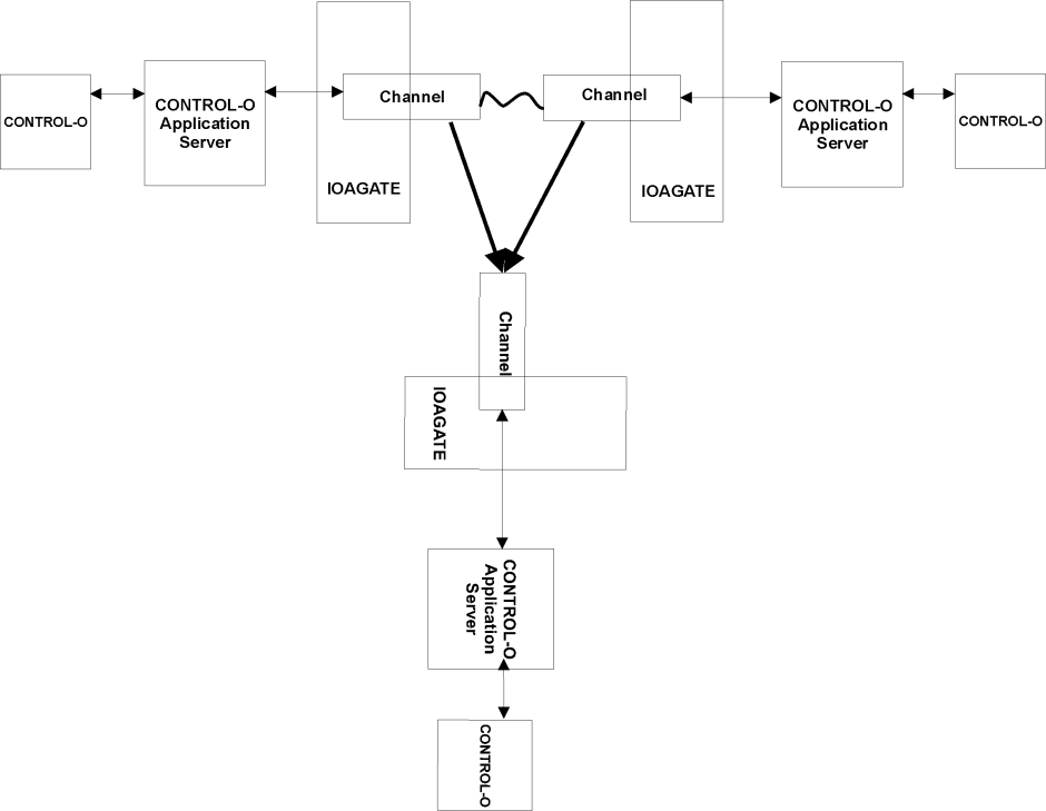
IOAGATE must be able to discern whether it is connecting to another IOAGATE gateway or directly to another application server. This is done by network mapping.
Defining the IOAGATE Network Map
Creating a network map to connect IOAGATEs on different machines at various sites requires defining the network map member in the IOA PARM library. The member name is specified by the NETWMAP parameter in ECAPARM. The IOA SAMPLE library contains a sample member, ECANWMAP, with sample definitions that can be customized for your site.
Planning the Network Map
All ECAPARM members of all IOAGATEs in your network must be defined. Each one should have a unique NODE (GTWID in previous versions).
Decide which application servers should communicate with each other. A sketch of all network entities and their connections should be drawn.
Example
This example illustrates SNA and TCP connections. For more information, refer to the ECANWAP member in the IOA SAMPLE library.
As Control-M JCL Verify supports only TCP/IP connections, the SNA examples are relevant only for Control-O.
There are three mainframes at the site:
-
MF01
-
MF02
-
MF03
Control-O and IOAGATE are installed on each one.
MF01 Definitions: The ECAPARM member includes:
|
For SNA |
|
|
|---|---|---|
|
CHANNEL |
ID=C1, |
Channel Identifier |
|
|
MODEL=MC, |
Multi-Connections Channel |
|
|
PROTOCOL=SNA, |
SNA |
|
|
NODE=GATE01, |
Node name |
|
|
NETWMAP=ECAABMAP, |
Network map to use in node |
|
|
APPLID=LU01 |
VTAM LU6.2 Application ID |
|
For TCP |
|
|
|---|---|---|
|
CHANNEL |
ID=C1, |
Channel Identifier |
|
|
MODEL=MC, |
Multi-Connections Channel |
|
|
PROTOCOL=TCP, |
TCP |
|
|
NODE=GATE01, |
Node name |
|
|
NETWMAP=ECAABMAP, |
Network map to use in node |
|
|
PORT=2760 |
Port for listening to incoming connections. |
MF02 Definitions: The ECAPARM member includes:
|
For SNA |
|
|
|---|---|---|
|
CHANNEL |
ID=C1, |
Channel Identifier |
|
|
MODEL=MC, |
Multi-Connections Channel |
|
|
PROTOCOL=SNA, |
SNA |
|
|
NODE=GATE02, |
Node name |
|
|
NETWMAP=ECAABMAP, |
Network map to use in node |
|
|
APPLID=LU02 |
VTAM LU6.2 Application ID |
|
For TCP |
|
|
|---|---|---|
|
CHANNEL |
ID=C1, |
Channel Identifier |
|
|
MODEL=MC, |
Multi-Connections Channel |
|
|
PROTOCOL=TCP, |
TCP |
|
|
NODE=GATE02, |
Node name |
|
|
NETWMAP=ECAABMAP, |
Network map to use in node |
|
|
PORT=2760 |
Port for listening to incoming connections. |
MF03 Definitions: The ECAPARM member includes:
|
For SNA |
|
|
|---|---|---|
|
CHANNEL |
ID=C1, |
Channel Identifier |
|
|
MODEL=MC, |
Multi-Connections Channel |
|
|
PROTOCOL=SNA, |
SNA |
|
|
NODE=GATE03s, |
Node name |
|
|
NETWMAP=ECAABMAP, |
Network map to use in node |
|
|
APPLID=LU03 |
VTAM LU6.2 Application ID |
|
For TCP |
|
|
|---|---|---|
|
CHANNEL |
ID=C1, |
Channel Identifier |
|
|
MODEL=MC, |
Multi-Connections Channel |
|
|
PROTOCOL=TCP, |
TCP |
|
|
NODE=GATE03, |
Node name |
|
|
NETWMAP=ECAABMAP, |
Network map to use in node |
|
|
PORT=2760 |
Port for listening to incoming connections. |
Application server CONTROLO in MF01 should communicate with CONTROLO in MF02, and application server CONTROLO in MF01 should communicate with CONTROLO in MF03.
The following figure illustrates the network map for the sample configuration.
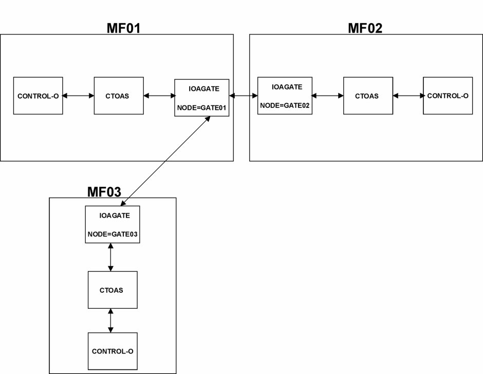
Coding the Network Map
When coding the network map in the IOA.PARM library member with the name specified in the ECAPARM NETWMAP parameter, BMC recommends that you code the network map for the whole network and distribute this member to all sites that run IOAGATE. Each IOAGATE is able to extract the relevant information for itself from the same global map definitions.
All the parameters in the network map are mandatory.
The following are sample coded network maps that correspond to the sample configuration in the Example above.
Figure 55 Sample Coded Network Map for SNA
LOCAL  APPL=CONTROLO,NODE=GATE01
                PARTNER APPL=CONTROLO,NODE=GATE02,LUNAME=LU02
                PARTNER APPL=CONTROLO,NODE=GATE03,LUNAME=LU03
                LOCAL  APPL=CONTROLO,NODE=GATE02
                PARTNER APPL=CONTROLO,NODE=GATE01,LUNAME=LU01
                LOCAL  APPL=CONTROLO,NODE=GATE03
            PARTNER APPL=CONTROLO,NODE=GATE01,LUNAME=LU01
Figure 56 Sample Coded Network Map for TCP
LOCAL  APPL=CONTROLO,NODE=GATE01
                PARTNER APPL=CONTROLO,NODE=GATE02,HOST=HOST2,
                PORT=2760,CONNECTOR=LOCAL
                PARTNER APPL=CONTROLO,NODE=GATE03,HOST=HOST3,
                PORT=2760,CONNECTOR=LOCAL
                LOCAL  APPL=CONTROLO,NODE=GATE02
                PARTNER APPL=CONTROLO,NODE=GATE01,
                CONNECTOR=PARTNER
                LOCAL  APPL=CONTROLO,NODE=GATE03
                PARTNER APPL=CONTROLO,NODE=GATE01,
            CONNECTOR=PARTNER
Each LOCAL statement defines a specific IOAGATE in the network. Each PARTNER statement under the LOCAL statement defines another remote IOAGATE with which this specific IOAGATE will communicate.
When an IOAGATE starts, it reads the network map member specified in the ECAPARM member and locates the LOCAL statement that corresponds to that IOAGATE. This LOCAL statement is the one that has the same value in the NODE parameter as the value coded in the NODE parameter of the ECAPARM member.
In the sample network map in Figure 43, because the IOAGATE on MF01 in Figure 42 has NODE set to GATE01 in the ECAPARM member, that IOAGATE locates the first LOCAL statement in the network map. That IOAGATE establishes a connection with each partner IOAGATE specified in the PARTNER statements under that LOCAL statement.
Considerations For SNA — The connection to the partner IOAGATE is the LUNAME specified on the PARTNER statement. This LUNAME must match the APPLID in the ECAPARM member of the partner IOAGATE. Each IOGATE initiates a connection to its partner IOAGATEs, so that between each pair of IOAGATEs there are two connections.
For example, in the configuration illustrated in Figure 42, the IOAGATE on MF01 connects to both LU02, which is the IOAGATE on MF02 (because it has APPLID=LU02), and LU03, which is the IOAGATE on MF03.
Each connection must be defined in both directions. If a connection is defined between CONTROLO on GATE01 and CONTROLO on GATE02, define both CONTROLOs as LOCALs connecting to each other as PARTNERs. A connection defined only in one direction cannot be established by IOAGATE.
Considerations For TCP — The connection to the partner IOAGATE is to the host and port specified by the HOST and PORT parameters, but only if CONNECTOR is set to LOCAL. If CONNECTOR is set to PARTNER, IOAGATE waits for the partner IOAGATE to initiate the connection. Therefore, you must define one IOAGATE with CONNECTOR set to LOCAL and the other with CONNECTOR set to PARTNER.
The PORT parameter defined in the MAP must match the port on which the partner IOAGATE listens for incoming connections. That port is defined in the ECAPARM CHANNEL statement of the partner IOAGATE.
In TCP, only one side initiates the connection.
For example, in the configuration illustrated in Figure 42:
-
IOAGATE on MF01 connects to both
-
port 2760 on HOST2, which is IOAGATE on MF02, because it listens to on port 2760 to HOST2
-
port 2760 on HOST3, which is IOAGATE on MF03
-
-
HOST2 must resolve to an IP address of TCP/IP on MF02
-
HOST3 must resolve to an IP address of TCP/IP on MF03
-
IOAGATE on MF02 and IOAGATE on MF03 wait for MF01 to initiate the connection
The CHANNEL definition on the connection initiator side requires a port to be defined for listening to incoming connections, even though this IOAGATE may never receive any connection from any client or peer. This port can be shared with a Control D/Page on Demand Application Server, in which case the port will be used to receive incoming connections from Control D/WebAccess Server.
The value of APPL can be any of the following:
-
J (for Control-M JCL Verify)
-
O (for Control-O)
-
CONTROLO
-
ControlO
Structure of the IOA Conditions File
The IOA Conditions file is comprised of the following parts:
-
1 physical record for synchronization purposes.
-
32 logical records for prerequisite conditions, as follows:
-
31 logical records; one for each day of the month.
-
1 logical record for STAT conditions.
-
The record size, in bytes, of a physical record in the IOA Conditions file is fixed at 32 KB.
The CNDREC# parameter specifies the number of physical records in each logical record.
Each prerequisite condition requires 24 bytes. Therefore, the number of conditions allowed for each date is equal to 1/24 of the 32 KB times the value specified for the CNDREC# parameter. You can also use long condition names. Each long condition name occupies two entries, or 48 bytes each.
Due to MVS access method limitations, a maximum of 32KB bytes can be specified for the record size of a physical record in the IOA Conditions file. This default value is the maximum block size for 3380 disks and 3390 DASD devices. This default allows a maximum of 1365 conditions in each prerequisite condition record of the IOA Conditions file.
If your site uses a large number of conditions such as OUT conditions created by Control‑M, and you require more than the maximum 32KB for each record in the IOA Conditions file, additional slots can be allowed for each record. For more information about this option, see "CNDREC#" in Parameters.
Use the following formula to calculate the region size needed for the IOA Conditions file:
32760 * ((32 * CNDREC#) + 2 + INT((CNDREC# - 1 ) / 255) )
The following examples illustrate the use of the formula:
-
If CNDREC# is set to 1, about 1.11 MB of virtual storage is needed to load the IOA Conditions file.
-
If CNDREC# is set to 2, about 2.16 MB of virtual storage is needed to load the IOA Conditions file.
For more information about the CNDREC# parameter, see Step 5 – Specify Target Configuration Parameters.
Housekeeping
The following topics describe various housekeeping options available from the Maintain your Environment option on the ICE Main Menu:
Accessing Housekeeping Activities
To access housekeeping activities, do the following:
-
Open the IOA Installation—Main menu.
-
Select the Maintain your Environment option.
-
Select the ICE refresh option.
The IOA Installation – ICE refresh screen is displayed.
Figure 57 IOA Installation: ICE Refresh Screen
--------------------- IOA Installation - ICE refresh  ------------------------
                OPTION  ===>
                Environment: DOC900
                Product: IOA               Enforce Step Order ==> YES
                   Reference Libraries Prefix: IOAP.V900
                   1  REFERENCE       - Insert Reference into Parameters Table
                   2  REFRESH TABLES  - Implement a New Set of ICE Tables
                   3  TAILOR JOB      - Tailor any Job from Installation Libraries
               4  COPY PROCEDURE  - Copy a Procedure to a Site Procedure Library
Reference
This option allows you to specify members of an existing installation from which values should be inserted into the reference column in the Parameters Table. Use this option to specify members other than the default members supplied during environment definition.
To access this option, do the following:
-
Type 1 in the OPTION field to select Option 1, REFERENCE, and press Enter.
The Reference Member Specification Panel is displayed.
Figure 58 Reference Member Specification Panel
Copy--------------------- Reference Member Specification Panel -------------------
COMMAND ===>
Product IOA Environment: DOC900
Reference Member
================
Type Dataset Name Member
DEFPARM ==> IOAP.V9zz.PARM ==> DEFPARM
xxxPARM ==> IOAP.V9zz.PARM ==> IOAPARM
The Reference release was determined according to the Reference libraries
prefix specified in the ENVIRONMENT table. Check/change the value.
Reference release ==> 900
Insert into REFERENCE column ==> YES (Yes/No) -
The reference values can be retrieved from a version 8.x.xx installation or a version 7.x.xx installation. To do this, type 800 or 700, as appropriate, in the Reference release field, and press Enter.
You can retrieve values from both the DEFPARM member and from the xxxPARM member or, if you want, from only one of these. If you leave the Member field blank in either line, no values will be retrieved from the data set referenced in that line.
-
When the process of retrieving the values has been completed, press Enter again. The IOA Installation – Main Menu is redisplayed.
Refresh Tables
Refreshes the current set of ICE tables, so that changes and modifications to the IOA and INCONTROL environments are implemented.
If a change results in the replacement of ICE tables, the new copy of the table must be merged with all values previously entered during installation, customization, and so on.
To refresh the ICE elements that were replaced by the change, type 2 in the OPTION field and press Enter.
The tables are refreshed.
After the tables are refreshed, the following message is displayed:
IOA7B8I ICE TABLES REPLACEDTailor Job
Modifies jobs in the installation libraries. This can be used as an alternative method for modifying jobs that reformat (recreate) INCONTROL product Data Sets. During the installation process, only the jobs you select are tailored before submission and saved in the INSTWORK library. This option provides you with a method for building, or rebuilding, any job from the installation libraries.
As a default, the job is built in a temporary file but you can save the file in the INSTWORK library if you choose.
To use this method, do the following:
-
Type 3 in the OPTION field and press Enter. The Build a Job Specification Panel for this option is displayed.
Figure 59 The Build a Job Specification Panel
Copy----------------------- Build a Job Specification Panel ----------------------
COMMAND ===>
Product Code ..... ==> CTx
Job to be Tailored ==>
Output Library ... ==> TEMP (TEMP=ISPF temporary file)
(INSTWORK=Standard ICE work library)
Press Enter to build the job PF3 to Exit -
Insert values for the parameters in this screen, as shown in the following table:
Table 175 Parameters in the Build a Job Specification Panel
Parameter
Description
Product Code
This parameter defaults to the INCONTROL product that corresponds to the Product ID that you specified.
Job to be Tailored
The member name.
Output Library
The output library to serve as the location for the tailored member.
Valid values are:
-
TEMP – The file is stored in a temporary location. Default.
-
INSTWORK – The file is stored in the INSTWORK library.
-
-
When you have inserted values for the parameters in this screen, press Enter.
The job is then built.
For information about members that are ISPF skeletons for creating, allocating, or formatting INCONTROL product Data Sets, see the section concerning data set formatting jobs for INCONTROL products in the INCONTROL for z/OS Administrator Guide.
Copy Procedure
Copies procedures to a site procedure library.
Certain situations require that you manually copy a procedure to a site procedure library. For example, if the SITEPROC IOA installation parameter is set to DONTCOPY, you must copy a modified version of the CTRTROLR procedure to a site procedure library.
To do this, do the following:
-
Type 4 in the OPTION field and press Enter. The Build a Job Specification Panel for this option is displayed.
Figure 60 Copy a Procedure Specification Panel
Copy----------------------- Build a Job Specification Panel Enter required field
COMMAND ===>
This utility copies an IOA procedure to a site procedure library.
The procedure is copied with remame after the necessary JCL statements
were inserted into it.
You can request that the members IOASET and IOAENV will be copied as well.
Input procedure name ==>
Output procedure name ==>
Site library ........ ==> DONTCOPY
Copy IOASET and IOAENV==> Y (Y/N)
Press Enter to copy the procedure PF3 to Exit -
Define the parameters in this screen as shown in the following table:
Table 176 Parameters in the Build a Job Specification Panel (2)
Parameter
Description
Input procedure name
Name of the procedure to copy.
Output procedure name
To rename the procedure, specify a procedure name. Otherwise, leave blank.
Site library
The name of your site procedure library.
Copy IOASET and IOAENV
Indication that you want the IOASET and IOAENV members copied also to the new site procedure library.
Valid values are:
-
Y – Copy the IOASET and IOAENV members. Default.
-
N – Do not copy the IOASET and IOAENV members.
-
-
Press Enter.
Uninstalling
This section discusses the uninstalling process activated from the INCONTROL Installation and Customization (ICE) Main Menu.
Before the uninstallion is performed, ICE displays a list of the datasets that were allocated by ICE for the current environment. These datasets will be deleted if you proceed with the uninstall. Review the list of datasets to ensure that these files are not used by another IOA environment, and then confirm that all the datasets are relevant to the current environment and can be deleted without affecting any other IOA environments.
Uninstalling an IOA Environment
This procedures describes how to uninstall an IOA environment.
Begin
-
On the main ICE panel, select Uninstallation.
-
When prompted, select the relevant environment.
-
When prompted, confirm that all the data sets are relevant to the current environment and can be deleted without affecting any other IOA environments.
Message Considerations
The JES, MVS, INCONTROL product and security (ACF2) messages listed in the following table should not be modified or suppressed by an automatic operator, since IOA and the INCONTROL products assume and are based on the original structure of these messages.
If you are implementing the Control-M NJE job tracking facility, also make sure that messages beginning with the remote NJE node name are not suppressed. For more information about extended NJE tracking support, see Step 10.3 – Extended NJE Support (Optional).
Table 177 Messages that Should Not Be Modified or Suppressed
|
Message |
Required by Products |
|---|---|
|
$HASP100 |
Control‑M, Control‑M/Restart |
|
$HASP373 |
Control‑M, Control-M/Restart |
|
$HASP395 |
Control‑M, Control‑M/Restart |
|
$HASP398 |
Control‑M, Control‑M/Restart |
|
$HASP608 |
Control‑M, Control‑M/Restart |
|
$HASP693 |
Control‑M, Control‑M/Restart |
|
$HASP826 |
Control‑M, Control‑M/Restart |
|
$HASP890 |
Control‑M, Control‑M/Restart |
|
ACF1007 |
Control‑M, Control‑M/Restart |
|
ACF1012 |
Control‑M, Control‑M/Restart |
|
CTMC41E |
Control‑M, Control‑M/Restart |
|
CTMC42E |
Control‑M, Control‑M/Restart |
|
CTO285E |
Control‑M, Control‑M/Restart |
|
CTR066I |
Control‑M, Control‑M/Restart |
|
CTR082I |
Control‑M, Control‑M/Restart |
|
CTR103I |
Control‑M, Control‑M/Restart |
|
CTT100A |
Control‑M, Control‑M/Restart |
|
CTT101A |
Control‑M, Control‑M/Restart |
|
CTT102A |
Control‑M, Control‑M/Restart |
|
CTT103A |
Control‑M, Control‑M/Restart |
|
CTT104A |
Control‑M, Control‑M/Restart |
|
CTT105A |
Control‑M, Control‑M/Restart |
|
IAT2000 |
Control‑M, Control‑M/Restart |
|
IAT2006 |
Control‑M, Control‑M/Restart |
|
IAT4801 |
Control‑M, Control‑M/Restart |
|
IAT5210 |
Control-M/Tape |
|
IAT5410 |
Control-M/Tape |
|
IAT6100 |
Control‑M, Control‑M/Restart |
|
IAT6101 |
Control‑M, Control‑M/Restart |
|
IEC101A |
Control-M/Tape |
|
IEC111E |
Control-M/Tape |
|
IEC151I |
Control‑M, Control‑M/Restart |
|
IEC501A |
Control‑M, Control-M/Restart, Control-M/Tape |
|
IEC501E |
Control-M/Tape |
|
IEC502E |
Control‑M, Control-M/Restart, Control-M/Tape |
|
IEC705I |
Control‑M, Control‑M/Restart |
|
IEF125I |
Control‑M, Control‑M/Restart |
|
IEF126I |
Control‑M, Control‑M/Restart |
|
IEF142I |
Control‑M, Control‑M/Restart |
|
IEF202I |
Control‑M, Control‑M/Restart |
|
IEF233A |
Control‑M, Control‑M/Restart, Control-M/Tape |
|
IEF233D |
Control‑M, Control‑M/Restart Control-M/Tape |
|
IEF234E |
Control‑M, Control‑M/Restart, Control-M/Tape |
|
IEF236I |
Control‑M, Control‑M/Restart |
|
IEF237I |
Control‑M, Control‑M/Restart |
|
IEF251I |
Control‑M, Control‑M/Restart, Control-M/Tape |
|
IEF253I |
Control‑M, Control‑M/Restart |
|
IEF272I |
Control‑M, Control‑M/Restart |
|
IEF283I |
Control‑M, Control‑M/Restart |
|
IEF285I |
Control‑M, Control‑M/Restart |
|
IEF287I |
Control‑M, Control‑M/Restart |
|
IEF373I |
Control‑M, Control‑M/Restart |
|
IEF374I |
Control‑M, Control‑M/Restart |
|
IEF375I |
Control‑M, Control‑M/Restart |
|
IEF376I |
Control‑M,Control‑M/Restart |
|
IEF378I |
Control‑M, Control‑M/Restart |
|
IEF379I |
Control‑M, Control‑M/Restart |
|
IEF403I |
Control‑M, Control‑M/Restart, Control-M/Tape |
|
IEF404I |
Control‑M, Control‑M/Restart, Control-M/Tape |
|
IEF450I |
Control‑M, Control‑M/Restart, Control-M/Tape |
|
IEF451I |
Control‑M, Control‑M/Restart |
|
IEF452I |
Control‑M, Control‑M/Restart |
|
IEF453I |
Control‑M, Control-M/Restart, Control-M/Tape |
|
IEF472I |
Control‑M, Control-M/Restart |
|
IEF607I |
Control‑M, Control-M/Restart |
|
IEF635I |
Control‑M, Control-M/Restart |
|
IEF653I |
Control‑M, Control-M/Restart |
|
IEFC452I |
Control‑M, Control-M/Restart |
|
IEFC607I |
Control‑M, Control-M/Restart |
|
IGD100I |
Control‑M, Control-M/Restart |
|
IGD101I |
Control‑M, Control-M/Restart |
|
IGD103I |
Control‑M, Control-M/Restart |
|
IGD104I |
Control‑M, Control-M/Restart |
|
IGD105I |
Control‑M, Control-M/Restart |
|
IGD107I |
Control‑M, Control-M/Restart |
|
IGD108I |
Control‑M, Control-M/Restart |
|
IGD1700I |
Control‑M, Control-M/Restart |
|
IGD1710I |
Control‑M, Control-M/Restart |
Control-M Virtual Storage Requirements
The following topics describe the virtual storage requirements of the Control‑M monitor, files, and utilities:
Control-M Monitor
The Control‑M monitor procedure Control-M is supplied with a default region size of 0 MB. The specified region size is honored by z/OS unless a local exit is employed to limit the region size of jobs and started tasks (STCs). The region size may be limited by MVS Exit IEALIMIT, by IEFUSI, or by other MVS and JES exits.
If Control‑M monitor startup fails due to insufficient region size, message IEF374I of the Control‑M monitor sysout can be examined to determine how much virtual storage was actually used.
At startup, the monitor obtains working storage. The monitor tries to allocate this storage above the 16 MB line. When the Journaling facility is enabled (parameter JRNL in member CTMPARM of the IOA PARM library is set to Y) storage above the bar (4GB) is also allocated.
Under certain circumstances, RMF and SDSF display incorrect real storage consumption of the monitor. They actually show virtual storage consumption. This can occur due to one or more of the following:
-
There is no paging activity in the z/OS system.
-
The Control-M monitor is running non-swappable.
In such cases, z/OS does not perform any page-outs and does not update its counters.
Calculations
Calculate the amount of virtual storage required by the Control‑M monitor by doing the following:
-
considering the number of records in the Active Jobs File (AJF), as defined by parameter AJFSIZE in member CTMPARM in the IOA PARM library
The monitor loads the entire Active Jobs file into virtual storage. Each entry of the Active Jobs file requires 1024 bytes. For example, assuming there are 20,000 records in the Active Jobs file, the Control-M monitor requires 20MB of storage above the 16MB line to process the Active Jobs file.
-
considering the number of records per day defined for the IOA Conditions file (CND), and the blocksize of each such record, which is 32 K (32760 bytes)
The monitor loads the entire CND file into virtual storage. When one record per day is defined by parameter CNDREC# in member IOAPARM, 1.05MB of virtual storage is needed by Control-M for the CND file.
If one condition record per day is not sufficient to contain the required number of conditions, multiple records per day can be defined by means of parameter CNDREC# in member IOAPARM. The default value of CNDREC# is 1. A maximum of 32 records per day can be specified. The total number of records in the CND file can be calculated as follows:
TOTAL CND RECORDS = (CNDREC# * 32) + 1
To determine the total amount of virtual storage required by the CND file, multiply the total number of records by the record length. For example: If parameter CNDREC# equals 2 and the CND file contains 65 records, 2.06MB virtual storage is needed by the Control-M monitor for the CND file.
-
determining how many records you need for quantitative and control resources. (This is usually done during product customization.) The system needs one additional record for its use
If, for example, you define 5 records for quantitative and 5 for control resources, Control-M needs (5+5+1) * 32K bytes of virtual memory to accommodate all resources.
-
adding space for the basic software used by the Control-M monitor, which requires between 750 to 1000K of virtual storage, depending on the environment and the functions used.
-
In-memory Trace facility:
The amount of virtual storage required by the Control-M monitor for the In-memory Trace facility (described in the IOA Admin guide) is determined by the buffer size specified in the member CTMTRCMx (x=L, M or H) in the CTM PARM library. The LINES parameter specifies the maximum number of lines to be held in memory. The calculation is as follows: Virtual Storage buffer required = Number of LINES * 192 The LINES parameter in the member may be modified by the user ifdesired. The virtual storage requirements for the Control-M Application server is determined by the buffer size specified in the member CTMTRCAx (x=L, M or H) in the CTM PARM library according to the formula above.
-
setting aside space for user dependent work areas and programs
-
the size of user exits and the destination tables
-
the maximum size of AutoEdit members referenced at job submission time
-
the blocksize of the JCL library and of the library that contains AutoEdit members
These items usually requires a small amount of virtual storage, and therefore it is not essential to calculate it exactly. However, remember to reserve some storage for these items.
-
-
when the JRNL parameter is set to Y, considering the number of records in the Control-M AJF for Journaling Synchronization image (CKPJNL), as defined by the AJFSIZE parameter in the CTMPARM member in the IOA PARM library. This storage is obtained above the bar.
-
periodically checking the content of message IEF374I in the sysout of the Control-M monitor to compare the actual storage requirements with the existing region size definition.
When specifying 30,000 Active Jobs file entries, 8 records per day for the IOA Conditions file, and five records for both the control records and the quantitative records in the Control‑M Resources (RES) file, a region size of 39.8 MB above the line (16MG) must be allocated according to the following calculation:
Table 178 Sample Calculation for Control‑M Monitor
|
Item |
Size |
Calculation |
|---|---|---|
|
Active Jobs file |
30.0 MB |
(30,000 x 1,024) |
|
Conditions file |
8.1 MB |
(32,760 x ((32 x 8)+1)) |
|
Resources file |
0.4 MB |
(32,760 x (5+5+1)) |
|
Basic software |
1.0 MB |
|
|
User-dependent |
0.3 MB |
|
|
TOTAL |
39.8 MB |
|
Control-M New Day Procedure
The amount of virtual storage required by the first step of the New Day procedure (procedure CTMTDAY) is determined by the size of the Active Jobs file plus the size of the IOA Conditions file (CND) plus the sizes of the Control‑M Resource files plus approximately 10% for additional areas required for processing.
If parameter HIST is set to YES in member CTMPARM (that is, History Active Jobs file processing is enabled), the amount of virtual storage required by the CLRHIST step of the CTMTDAY procedure is determined by the size of the History file plus approximately 10% for additional areas required for processing.
Utility CTMCAJF
The COMPRESS function of utility CTMCAJF requires the same amount of virtual storage as the Control‑M New Day procedure for the Active Jobs file.
The COPY utility requires virtual storage equivalent to the sum of the source and target files.
Defining Subsystems
In MVS, a subsystem can be defined dynamically or by adding it to an IEFSSNnn PARMLIB member. The definition in the IEFSSNnn member applies only after the next IPL. The dynamic definition applies immediately and lasts until the next IPL. The following topics describe how to define subsystems:
This section is relevant for the subsystems used by IOA, Control-D Compressed Access Method (CDAM), Control-O, Control-M Event Manager (CMEM), IOA Archive Server subsystem, and the IOA Online Monitor. This section does not deal with the Control-M/Tape subsystem which is explained in Installing Control-M/Tape.
Subsystem Definition
Edit the IEFSSNnn member in the SYS1.PARMLIB library, where nn is the suffix specified in the IEASYS member in the SYS1.PARMLIB library. If the suffix is not specified in the IEASYS, the default is 00. The subsystem can be defined using positional or keyword parameter structure.
-
When using the keyword parameter structure, add a record to the IEFSSNnn member in the following format:
CopySUBSYS SUBNAME(xxxx)where xxxx is the name of the subsystem
-
When using the positional parameter structure, add a record to the IEFSSNnn member in the following format:
xxxx
where xxxx is the name of the subsystem
INCONTROL subsystems are initialized when their corresponding monitors are started. There is no need to define them in the IEFSSNnn member.
They can be defined in IEFSSNnn member without specifying a subsystem initialization routine.
If INCONTROL subsystems are defined, their position in the IEFSSNnn member is not important (see Special Considerations for Control-O).
INCONTROL subsystems are not affected by the BEGINPARALLEL statement, which might appear in IEFSSNnn, because INCONTROL subsystems have no subsystem initialization routines and the BEGINPARALLEL statement indicates that the subsystem initialization routines specified in SUBSYS statements that follow the BEGINPARALLEL statement are invoked in parallel.
For more information, see the relevant IBM MVS Initialization and Tuning Reference.
Dynamic Subsystem Definition
There are number of ways a subsystem can be dynamically defined without having to perform an IPL.
-
When an INCONTROL product or component is started and its subsystem is not defined, it can define the subsystem dynamically. The subsystem is added at the end of the subsystem chain and remains until the next IPL. Using this method, the subsystem does not have to be defined in IEFSSNnn.
The decision whether dynamic definition is allowed is controlled by the IOA Installation SSALLOC parameter or, for the IOA Online Monitor, by the IOA Online Monitor global Dynamic definition parameter.
For more information see the explanations for these parameters in the relevant product sections of this manual.
-
The subsystem can be defined using the following operating system command:
CopySETSSI ADD,SUB=xxxxwhere xxxx is the name of the subsystem
For more information, see the description of the SETSSI command in the IBM MVS System Commands manual.
-
Certain products can define a subsystem dynamically. To use this method, see the appropriate product manual.
Special Considerations for Control-O
To enable Control-O to change or suppress subsystem commands (for example, commands for DB2 that start with the '-' character), the Control-O subsystem must be defined in the IEFSSNnn member BEFORE the definition of the target subsystems of these commands.
An exception to this rule is the interception of JES2 commands using the IEFJFRQ dynamic subsystem exit, instead of a Control-O subsystem. For more information, see the JCMDSSN parameter in Step 2.1 – Control-O Operational Parameters.
National Language Support Facility
BMC enables you to configure your system to support one or more of the following national languages, in addition to English:
-
French
-
German
-
Japanese
The following topics describe the National Language Support installation:
Ensure that you have installed IOA before beginning the National Language Support installation.
System Installation Preparation
Install the National Language Support (NLS) from one of the following sources:
-
The BMC Electronic Product Distribution (EPD) site
-
CD
Installing NLS
This procedure describes how to install NLS.
Begin
-
Prepare your system.
For information about the space requirements, see the INCONTROL for z/OS release notes that accompany this release. The DCB information for the image file is as follows:
CopyRECFM=FB, LRECL=1024, BLKSIZE=27648 -
Transfer the image file to the mainframe as a binary file, by doing one of the following actions:
-
Download the National Language Support installation from the EPD site at http://www.bmc.com/available/epd.html
-
Copy the file from the productCD.
-
-
Uncompress the image file.
The IBM TRSMAIN (alias of AMATERSE) program is required because the image files are delivered in a compressed format that was created using TRSMAIN.
-
Once the image file has been uploaded to your mainframe, make the necessary changes in the following UNTERSE job to uncompress the image file.
Copy**************************** Top of Data ******************************
//UNTERSE JOB <=== tailor job card to local standards
//*
//UNTERSES EXEC PGM=TRSMAIN,PARM=UNPACK
//SYSPRINT DD SYSOUT=*
//INFILE DD DISP=SHR,DSN=uploaded.image.file <===UPDATE
//OUTFILE DD DISP=(NEW,CATLG,DELETE),
// UNIT=disk_unit,VOL=SER=disk_volser, <===UPDATE
// DSN=basepref.NLSSUPP, <===UPDATE
// SPACE=(CYL,(ppp,ss,dd)) <===UPDATE
*************************** Bottom of Data ****************************In the preceding UNTERSE job:
-
basepref represents your choice of prefix for the base libraries, which are described in Loading ICE.
-
ppp,ss,dd represents the space requirements for the basepref.NLSSUPP file, as specified in the INCONTROL for z/OS release notes that accompany this release.
-
-
Submit the UNTERSE job.
-
Verify that the job completes with a return code of 0.
-
Installing National Language Support
This procedure describes how to install national language support.
Begin
-
Select Customization from the ICE main menu.
-
Select an environment.
-
Specify product IOA.
-
Select Product Customization.
-
Select step 19 (Install National Language Support).
-
Select minor step 1 (Select additional languages).
-
Select minor step 2 (Apply the National Language Support).
These steps build the NLSINST job in the IOA INSTWORK library.
-
The NLSINST job is tailored according to the languages selected in minor step 1. In the following steps, lng represents the language selected for the installation, where
-
FRA or FR represents the French national language
-
GER or GE represents the German national language
-
JPN or JP represents the Japanese national language
The following table describes the jobs used to install national language support.
Table 179 National language Support Installation Steps
Step name
Description
ALLOCT
This job allocates the target and distribution language libraries, as follows:
-
The target language libraries names are:
-
ilprefa.ISMSGlng
-
ilprefa.MSGlng
-
ilprefa.PANELlng
-
The distribution language libraries names are:
-
spdpref.AISMSGlng
-
spdpref.AMSGlng
-
spdpref.APANELlng
ADDDDEF
Adds SMP/E DDDEFs for language target and distribution libraries.
RCV*
Performs the RECEIVE operation for the language FMIDs and PTFs, which are located in the lang8000 member in the BASEPREF.NLSSUPP library.
The asterisk in the final character of the step name represents
-
F - if the French national language has been selected
-
G - if the German national language has been selected
-
J - if the Japanese national language has been selected
APPLCHK
Performs the APPLY CHECK operation for the language FMIDs and PTFs.
APPLY
Performs the APPLY operations for the language FMIDs and PTFs.
ACPTCHK
Performs the ACCEPT CHECK operation for the language FMIDs and PTFs.
ACCEPT
Performs the ACCEPT operation for the language FMIDs and PTFs.
-
Japanese and French Screen Display Considerations
In order to complete the installation of Japanese or French language support, the Japanese and French version of IOAX037 (IOA user Exit 37) should be installed. This version is used to translate specific hexadecimal values. To install, follow the steps below.
Begin
-
Enter ICE.
-
Select Customization.
-
Select an environment.
-
In the Customization screen, set the Product ID to IOA.
-
Select Product Customization.
-
Select Step 4 (User EXITS Installation).
-
Select Minor Step 2 (EXITs Customization).
-
In the select Exit field, specify either the source of sample exit IOAX037J or IOAX037F is tailored to support the Japanese or French language support that you have installed.
-
Press PF3 to continue.
Review the IOAX037 translation exit to verify that special characters of the selected language are translated correctly.
-
Submit JOB UMAX037J or IOAX037F to install this version of Exit 37 in your system.
The first time that you run this job, it will complete with a condition code of 12. Examine the SMPOUT for this step, and verify that the only SMP/E command which completed with a condition code of 12 is the REJECT command. All other SMP/E commands should complete with a completion code of 0 (zero).
For further information on modifying this exit, refer to the description of Exit IOAX037 in the Exits chapter of the INCONTROL for z/OS Administrator Guide.
Language Selection
Language selection is specified by the LANG parameter during the installation of INCONTROL. For further information on language selection, refer to Step 4.2 – IOA Operational Parameters, and "Step 2.4.2, IOA Operational Parameters", of the INCONTROL Installation and Customization Engine (ICE).
General Parameter Descriptions
ICE does not perform validity checks on these parameters.
Table 180 General Data Set Allocation Parameters
|
Name |
Description |
|---|---|
|
SMS Classes |
Data, Management, Storage In system-managed storage environments, use these parameters to specify information to the ACS routines and installation exits, to help them determine the SMS Classes for the corresponding data set and decide whether it is to be SMS-managed or non-SMS-managed.
|
|
Unit |
In system-managed storage environments, use this parameter to specify information to the ACS routines and installation exits, to help them determine the SMS Classes for the corresponding data set and decide whether it is to be SMS-managed or non-SMS-managed. In non-SMS environments, or for Data Sets that are non-SMS-managed, specify either a Generic Unit (such as 3390) or an Esoteric Unit (such as SYSDA), unless otherwise instructed.
|
|
Volume |
In system-managed storage environments, use this parameter to specify information to the ACS routines and installation exits, to help them determine the SMS Classes for the corresponding data set and decide whether it is to be SMS-managed or non-SMS-managed. In non-SMS environments, or for Data Sets that are non-SMS-managed, specify a real disk volume serial that matches the Unit parameter.
|
Installation Guide Planning Sheets
Installation planning sheets are included for the following types of installations:
Express Installation
Installation planning sheets for the Express installation are located in the following section.
For additional details about parameters, see the installation process described for each specific product.
Express Installation Sheet
A. Identity Installation Environments |
|||||||||||||||||||||||||||||||||||||||||||||||||||||||
|
_______ Test _______ Production Environment Name _______________________ |
The general overall ICE installation workflow is as follows:
The first step in the installation procedure defines the IOA environment to be installed and identifies it as a test or production installation. For details, see Performing Tasks Common to All Product Installations, especially Figure 5 “IOA Installation – Environment definition screen”, with values and Table 1 “Environment values in the Environment definition screen”. An environment name may contain a maximum of 8 characters. It will be used also as the IOA QNAME. |
||||||||||||||||||||||||||||||||||||||||||||||||||||||
B. IOA LOAD Library |
|||||||||||||||||||||||||||||||||||||||||||||||||||||||
|
Data set name (DSNAME, such as IOA.PROD.LOAD): ______________________________________ |
Specify the data set name for the IOA LOAD library (for example, IOA.PROD.LOAD). Use the LOAD library as a STEPLIB in the JCL procedures, or incorporate it into the MVS LINKLIST. Before deciding whether to use the library as a STEPLIB or in the LINKLIST, review the general considerations and the site standards for program product LOAD libraries. Then consider the following: Using STEPLIB
Using LINKLIST
|
||||||||||||||||||||||||||||||||||||||||||||||||||||||
C. Reference Libraries Prefix |
|||||||||||||||||||||||||||||||||||||||||||||||||||||||
|
_________________________________________ |
Prefix for high level data set name qualifiers (prefix) of the installation libraries to be used as reference libraries. |
||||||||||||||||||||||||||||||||||||||||||||||||||||||
D. Allocation Attributes |
|||||||||||||||||||||||||||||||||||||||||||||||||||||||
|
Unit:________ Vol Ser:________
SMS Classes: Data:____________Management:___________ Storage:___________ |
Specify the allocation attributes at the environment definition screen. These specifications will be used for all the selected products and for all libraries' categories. You can modify these paramaters at the allocation screen. Product Control-O obligates unit and volser for operational libraries. |
||||||||||||||||||||||||||||||||||||||||||||||||||||||
E. Products To Be Installed and Capacities |
|||||||||||||||||||||||||||||||||||||||||||||||||||||||
|
Select the INCONTROL products to be installed and each product's capacity. Use the following capacity indicators:
Default capacity is M. However, if a product is not to be installed, the capacity setting is ignored. Select the INCONTROL products from Table 1 to be installed at your site with a Y in the Y/N column in the Products and Sizes screen (default is N). For each selected product (indicated with a Y), specify the installation capacity size. Default is M. |
||||||||||||||||||||||||||||||||||||||||||||||||||||||
|
Control-M:
|
|||||||||||||||||||||||||||||||||||||||||||||||||||||||
|
Control-M/Analyzer:
|
|||||||||||||||||||||||||||||||||||||||||||||||||||||||
|
Control-M/Tape:
|
|||||||||||||||||||||||||||||||||||||||||||||||||||||||
|
Control-D: 1. Missions
2. Reports
3. Archives
|
|||||||||||||||||||||||||||||||||||||||||||||||||||||||
|
Control-O:
|
|||||||||||||||||||||||||||||||||||||||||||||||||||||||
F. Data Set Configuration |
|||||||||||||||||||||||||||||||||||||||||||||||||||||||
|
High-level qualifier prefix: _________________________________ Select the file naming format: ______ (HPC/HCP)
Specify EAV ability: ______ NO (OPT/NO/Empty) |
Specify a naming convention that will apply to all the allocated data sets, by doing the following: Specify the high-level qualifier (header) prefix. The default is the installation prefix from the environment creation panel. Select the file-naming format from the two options: HPC or HCP where
Default value which will be set to the following EAVUSE parameters allowing allocation of some Data Sets on EAV (Extended Address Volumes):
Only use the OPT value for the allocation of the installation Data Sets that are listed above. Use of the OPT value for other Data Sets is not supported and might lead to unpredictable results. |
||||||||||||||||||||||||||||||||||||||||||||||||||||||
G. ISPF Libraries Prefix of the O.S. |
|||||||||||||||||||||||||||||||||||||||||||||||||||||||
|
_________________________________________________________ |
ISPF product library prefix. Default: ISP. |
||||||||||||||||||||||||||||||||||||||||||||||||||||||
H. ISPF Language Suffix of the O.S. |
|||||||||||||||||||||||||||||||||||||||||||||||||||||||
|
_________________________________________________________ |
Specify ISPF language suffix of the O.S. from the following list:
|
||||||||||||||||||||||||||||||||||||||||||||||||||||||
I. Products (According to Previous Selection) |
|||||||||||||||||||||||||||||||||||||||||||||||||||||||
|
|||||||||||||||||||||||||||||||||||||||||||||||||||||||
J. Job Cards Data |
|||||||||||||||||||||||||||||||||||||||||||||||||||||||
|
JOBNAME: ____________________________ JOBCARD: ____________________________ JCL1: _________________________________ JCL2: _________________________________ |
Copy
Resulting job statement: Copy
|
||||||||||||||||||||||||||||||||||||||||||||||||||||||
K. Started Task and Procedure Libraries |
|||||||||||||||||||||||||||||||||||||||||||||||||||||||
|
Started tasks library (PROCLIB) ___ Use the supplied PROCJCL directly ___ Copy started tasks to site PROCLIB PROCLIB DSNAME: ___________________
Procedure library (SITEPROC) ___ Copy some JCL procedures to SITEPROC SITEPROC DSNAME:________________ |
Started Tasks Library (PROCLIB) The PROCJCL library contains all the started tasks. All the members in this library are jobs. Therefore, DDNAME IEFJOBS, which is in the MSTJCLxx member of SYS1.PARMLIB, must point to the library in which these members reside. You can define the PROCJCL library in your system as a started task library, or copy started tasks from the IOA PROCJCL library into an existing started tasks library. To specify the DSNAME of an existing started tasks library, use the PROCLIB installation parameter. Started tasks are customized during the installation process for each environment. Procedure Library (SITEPROC) The PROCLIB library contains all the procedures to be used in jobs. Each job supplied already contains a JCLLIB statement to enable the job to use this library. You can also copy a small number of selected procedures into an existing procedure library. The SITEPROC installation parameter specifies the DSNAME of an existing procedure library. If you do this, make sure that the names of new JCL procedures are different from existing ones. |
||||||||||||||||||||||||||||||||||||||||||||||||||||||
L. Data Sets Prefixes |
|||||||||||||||||||||||||||||||||||||||||||||||||||||||
|
If your configurations are not compatible with Express installation conventions for Data Sets naming according to the HPC/HCP format, use the following information. |
|||||||||||||||||||||||||||||||||||||||||||||||||||||||
IOA |
|||||||||||||||||||||||||||||||||||||||||||||||||||||||
Legend:
The IOA Online monitor requires:
|
Review site practices for allocating program product libraries and Data Sets. Determine which systems access each data set in the current installation and in future activities, such as changing from TEST to PRODUCTION and replicating production systems. Determine implied naming conventions and data set placement constraints. Catalog libraries residing in LINKLIST in the Master Catalog. Make data set names different from names in existing installations of IOA products. Base Base libraries are used as a base (skeleton) for creating certain environment-specific libraries. The Installation and Customization Engine (ICE) also resides in a base library. Installation Installation libraries are static product libraries that contain various program elements. These elements generally change only during product installation, maintenance and customization—but not as a result of ongoing operation. Operational Operational libraries contain operational information such as scheduling tables in Control-M, or print mission definitions in Control-D. Most operational libraries are updated regularly by users and are referenced during automatic operation of the product. Core The IOA core contains files that are used by all INCONTROL products. To improve performance, assign the log to a different volume and unit. To allocate IOA installation or operations libraries on DF/SMS managed volumes, do one of the following: Specify a volume serial number and/or unit that will be handled by your site's ACS routines. Leave the UNIT and VOLUME installation parameters empty. Maintenance MLPREFA: High level data set name qualifiers (prefix) of the IOA Maintenance libraries. MLVOLA: Serial number of volume on which IOA Maintenance libraries are placed. MLUNITA: Unit of disk on which IOA Maintenance libraries are placed. SMP CSI IOA supplies the CSI, SMPPTS, MTS, STS, LTS, and SCDS SMP/E Data Sets. Choose other SMP data set names and organization according to your local practices. Configure SMP CSI libraries in any of the following ways:
|
||||||||||||||||||||||||||||||||||||||||||||||||||||||
Control-M |
|||||||||||||||||||||||||||||||||||||||||||||||||||||||
Legend:
See additional requirements in the explanation for this item in the text at the right. |
Examples of DSN prefixes: CTM. V9000I for Control-M Installation libraries. CTM. V9000O for Control-M Operations libraries. CTM. V9000D for Control-M Repository. To access Control-M Data Sets and to use the basic facilities of Control-M, the Control-M monitor requires: READ and UPDATE access to JES spool SYSOUT datasets. Authority to issue operator commands. Authority to submit jobs. READ access to all schedule and JCL libraries. UPDATE access to IOA and Control-M Repositories and product Data Sets. If User Dailies are not owned by the IOA administrator, user categories 2,3,4 require UPDATE access to the Control-M PARM library. The Control-M New Day procedure and jobs that issue operator commands require authority to issue these operator commands. |
||||||||||||||||||||||||||||||||||||||||||||||||||||||
Control-M/Restart |
|||||||||||||||||||||||||||||||||||||||||||||||||||||||
Legend:
|
This item specifies Control-M/Restart data set access requirements. Examples of data set prefixes: CTR.V9000O for Control-M/Restart Operations libraries |
||||||||||||||||||||||||||||||||||||||||||||||||||||||
Control-M/Analyzer |
|||||||||||||||||||||||||||||||||||||||||||||||||||||||
Legend:
|
Examples of data set prefixes:
|
||||||||||||||||||||||||||||||||||||||||||||||||||||||
Control-D |
|||||||||||||||||||||||||||||||||||||||||||||||||||||||
Legend:
For additional requirements, see the explanation for this item in the text at the right. |
Examples of data set prefixes:
To access Control–D Data Sets and to use the basic facilities of Control–D, the following access authorizations are recommended.
The Control-D New Day procedure (CTDNDAY):
Jobs that change the order of missions require UPDATE access to the Control-D PARM library. The job that executes the CTDDELRP utility requires UPDATE access to the SCRLIST file: Backup and restore jobs require UPDATE access to the Control–D Active Missions file. |
||||||||||||||||||||||||||||||||||||||||||||||||||||||
Control-V |
|||||||||||||||||||||||||||||||||||||||||||||||||||||||
Legend:
For additional requirements, see the explanation for this item in the text at the right. |
Examples of data set prefixes:
To access Control–V Data Sets and to use the basic facilities of Control–D, the access authorizations shown for this item in the table at the left are recommended. In addition, migration jobs require UPDATE access to the Active User file and to the Migration User file |
||||||||||||||||||||||||||||||||||||||||||||||||||||||
Control-O |
|||||||||||||||||||||||||||||||||||||||||||||||||||||||
|
Examples of data set prefixes:
|
||||||||||||||||||||||||||||||||||||||||||||||||||||||
Control-M/Tape |
|||||||||||||||||||||||||||||||||||||||||||||||||||||||
Legend:
|
This item specifies the Control-M/Tape data set access requirements. Examples of data set prefixes:
Category 5 users do not require authorization if are no Control-M/Tape exits used to deny access. |
||||||||||||||||||||||||||||||||||||||||||||||||||||||
Customized Installation
Detailed installation planning sheets are included for the following INCONTROL products:
IOA Installation Sheet
A. Identity Installation Environments |
||||||||||||||||||||||||||||||||||||||||||||||||||
|
____ Test ____ Production Environment Name__________________________________ |
The general overall ICE installation workflow is as follows:
The first step in the installation procedure defines the IOA environment to be installed and identifies it as a test or production installation. For details, see Performing Tasks Common to All Product Installations, especially Figure 5 “IOA Installation – Environment definition screen”, with values and Table 1 “Environment values in the Environment definition screen”. An environment name may contain a maximum of 8 characters. It will be used also as the IOA QNAME. |
|||||||||||||||||||||||||||||||||||||||||||||||||
B. IOA Load Library |
||||||||||||||||||||||||||||||||||||||||||||||||||
|
Data set name (DSNAME, such as IOA.PROD.LOAD: _____________________________________________
|
Specify the data set name for the IOA LOAD library (for example, IOA.PROD.LOAD). You may use the LOAD library as a STEPLIB in the JCL procedures, or you may incorporate it into the MVS LINKLIST. Before deciding whether to use the library as a STEPLIB or in the LINKLIST, review the general considerations and the site standards for program product LOAD libraries. Then consider the following: Using STEPLIB
Using LINKLIST
|
|||||||||||||||||||||||||||||||||||||||||||||||||
C. Reference Libraries Prefix |
||||||||||||||||||||||||||||||||||||||||||||||||||
|
________________________________________________ |
Prefix for high level data set name qualifiers (prefix) of the installation libraries to be used as reference libraries. |
|||||||||||||||||||||||||||||||||||||||||||||||||
D. IOA Variable Databases |
||||||||||||||||||||||||||||||||||||||||||||||||||
|
If you install Control‑M or Control‑O, see Step 7 – Set Global Variables Database in the chapter about installing IOA, in the INCONTROL for z/OS Administrator Guide. |
|||||||||||||||||||||||||||||||||||||||||||||||||
E. Primary Language |
||||||||||||||||||||||||||||||||||||||||||||||||||
|
English ___French ___ German ___ Japanese |
Determine the primary language to be used. |
|||||||||||||||||||||||||||||||||||||||||||||||||
F. Started Task and Procedure Libraries |
||||||||||||||||||||||||||||||||||||||||||||||||||
|
Started tasks library (PROCLIB) ___ Use the supplied PROCJCL directly ___ Copy started tasks to site PROCLIB PROCLIB DSNAME: ___________________ Procedure library (SITEPROC) ___ Copy some JCL procedures to SITEPROC SITEPROC DSNAME:________________ Three character prefix for IOA procedures: _______ |
Started Tasks Library (PROCLIB) The PROCJCL library contains all the started tasks. All the members in this library are jobs. Therefore, DDNAME IEFJOBS, which is in the MSTJCLxx member of SYS1.PARMLIB, must point to the library in which these members reside. You can define the PROCJCL library in your system as a started task library, or copy started tasks from the IOA PROCJCL library into an existing started tasks library. To specify the DSNAME of an existing started tasks library, use the PROCLIB installation parameter. Started tasks are customized during the installation process for each environment. Procedure Library (SITEPROC) The PROCLIB library contains all the procedures to be used in jobs. Each job supplied already contains a JCLLIB statement to enable the job to use this library. You can also copy a small number of selected procedures into an existing procedure library. The SITEPROC installation parameter specifies the DSNAME of an existing procedure library. If you do this, make sure that the names of new JCL procedures are different from existing ones. |
|||||||||||||||||||||||||||||||||||||||||||||||||
G. Data Set Configuration |
||||||||||||||||||||||||||||||||||||||||||||||||||
|
Environment: _______________________________________________
|
When you choose data set parameters for IOA libraries and Data Sets, you should do the following:
Minor step 3.2 "Allocate IOA Libraries" allocates prefixes for all libraries. After prefixes are allocated, they can be modified as soon as the previous Data Sets are deleted and libraries are restored. Examples of data set name prefixes.
Base Base libraries are used as a base (skeleton) for creating certain environment-specific libraries. The Installation and Customization Engine (ICE) also resides in a base library. Installation Installation libraries are static product libraries that contain various program elements. These elements generally change only during product installation, maintenance and customization—but not as a result of ongoing operation. Operational Operational libraries contain operational information such as scheduling tables in Control-M, or print mission definitions in Control-D. Most operational libraries are updated regularly by users and are referenced during automatic operation of the product. Core The IOA core contains files that are used by all INCONTROL products. To improve performance, assign the log to a different volume and unit. To allocate IOA installation or operations libraries on DF/SMS managed volumes, do one of the following:
Maintenance MLPREFA: High level data set name qualifiers (prefix) of the IOA Maintenance libraries. MLVOLA: Serial number of volume on which IOA Maintenance libraries are placed. MLUNITA: Unit of disk on which IOA Maintenance libraries are placed. |
|||||||||||||||||||||||||||||||||||||||||||||||||
H. Type of Access to IOA Data Sets |
||||||||||||||||||||||||||||||||||||||||||||||||||
Legend:
The IOA Online monitor requires:
|
This section specifies the access requirements for different dataset types by user category. Maintenance files store the PTFs (program fixes) for IOA programs and JCL, as well as the jobs that implement them. |
|||||||||||||||||||||||||||||||||||||||||||||||||
I. SMP Data Sets |
||||||||||||||||||||||||||||||||||||||||||||||||||
Zone Names Target: ________ (For example, IOA9TZN) Distribution: ________ (For example, IOA9DZN) |
IOA supplies the CSI, SMPPTS, MTS, STS, LTS, and SCDS SMP/E Data Sets. Choose other SMP data set names and organization according to your local practices. SMP CSI Configure SMP CSI libraries in any of the following ways:
See Step 2.4 – SMP CSI Configuration for details about each configuration. |
|||||||||||||||||||||||||||||||||||||||||||||||||
J. System Changes |
||||||||||||||||||||||||||||||||||||||||||||||||||
|
Determine which system changes are relevant to your site.
|
To determine which of the listed system changes are relevant to your site, see the step that describes that subject, as follows: |
|||||||||||||||||||||||||||||||||||||||||||||||||
K. CPU Configuration of this IOA Environment |
||||||||||||||||||||||||||||||||||||||||||||||||||
|
SMF ID ________ JES2 SID ___________________ SMF ID ________ JES2 SID ___________________ SMF ID ________ JES2 SID ___________________ |
For each CPU in the target IOA environment, get the SMF ID. For JES2 systems, get the SID number. Step 6 – Customization Process Minor step 3 "Specify IOA CPUs" |
|||||||||||||||||||||||||||||||||||||||||||||||||
L. Password Information Available |
||||||||||||||||||||||||||||||||||||||||||||||||||
|
Yes ____ No ____ |
Verify that you have all password information required for the INCONTROL products you are installing. |
|||||||||||||||||||||||||||||||||||||||||||||||||
M. Libraries Related to ISPF |
||||||||||||||||||||||||||||||||||||||||||||||||||
|
_____ Use IOA supplied libraries _____ Copy IOA members to the site libraries |
Some IOA libraries contain ISPF panels, tables, messages, and skeletons, as well as the TSO CLIST library. To use these members, access them in the original libraries or copy them to other libraries. To use members in the original library, concatenate them to the appropriate DD statements of the logon procedures. For details see Step 8 – Install ISPF Support (Optional). |
|||||||||||||||||||||||||||||||||||||||||||||||||
N. Install the IOA Online Monitor |
||||||||||||||||||||||||||||||||||||||||||||||||||
|
Yes _____ No _____ |
You can use IOA online facilities in the following ways:
You can access the IOA online monitor through interfaces to VTAM, CICS, IMS/DC, IDMS/DC, COM-PLETE, ROSCOE, IOAVMON, and from TSO (using cross-memory services). Whether to install the IOA online monitor depends on the online facilities used at your site and the different types of users. For example, users who already use TSO for their operations can access INCONTROL products through TSO, as usual. However, those who are not familiar with TSO should probably use the IOA online monitor. |
|||||||||||||||||||||||||||||||||||||||||||||||||
O. Install National Language Support |
||||||||||||||||||||||||||||||||||||||||||||||||||
|
Yes _____ No _____ |
If you plan to implement French, German, or Japanese national language support, install it through Step 6 (Install National Language Support) in the ICE CUSTOMIZE section. |
|||||||||||||||||||||||||||||||||||||||||||||||||
Control-M Installation Sheet
A. Number of Jobs to Run Each Day |
|||||||||||||||||||||
|
________________ |
The number of jobs Control-M will handle each day. When calculating the Control-M AJF file size, multiply this number by 2. See the AJFSIZE parameter in Table 57 in for details. Maximum 9 digits. Minimum value 1000." |
||||||||||||||||||||
B. Mirror Active Jobs File Required |
|||||||||||||||||||||
|
Yes _____ No _____ |
Sometimes referred to as dual DB. See the DUALDB parameter in Mirror File for IOA Conditions. |
||||||||||||||||||||
C. Selected SYSOUT HLDCLASS |
|||||||||||||||||||||
|
________________ |
This 1-character string specifies the held sysout class used by jobs that Control-M submits. See the INCONTROL for z/OS Administrator Guide for details. |
||||||||||||||||||||
D. Install Control-M Event Manager (CMEM) |
|||||||||||||||||||||
|
Yes _____ No _____ |
If the Control-M Event Manager (CMEM) will be installed, define the subsystem so that MVS will recognize it. See Step 7 – Install Event Manager (CMEM)/Control-O Interface. |
||||||||||||||||||||
E. CTMPLEX Support |
|||||||||||||||||||||
|
Yes _____ No _____ |
Control‑M Sysplex support. For more information, see the section on CTMPLEX in Control‑M chapter of the INCONTROL for z/OS Administrator Guide. |
||||||||||||||||||||
F. Data Set Name (DSN) Prefixes, Volumes, and Units |
|||||||||||||||||||||
Library Type DSN Prefix Volume Unit Installation ILPREFM ILVOLM ILUNITM OLPREFM OLVOLM OLVOLM DBPREFM DBVOLM DBUNITM Statfile ILPREFM VSVOLM |
Step 4.4 – Install Control-M Libraries allocates prefixes for all libraries. After prefixes are allocated, they can be modified as soon as the previous Data Sets are deleted and libraries are restored. DSN prefixes:
|
||||||||||||||||||||
G. Type of Access to Control-M Data Sets |
|||||||||||||||||||||
Legend:
See additional requirements in the explanation for this item in the text at the right. |
To access Control‑M Data Sets and to use the basic facilities of Control‑M, the Control‑M monitor requires:
If User Dailies are not owned by the IOA administrator, user categories 2,3,4 require UPDATE access to the Control‑M PARM library. The Control‑M New Day procedure and jobs that issue operator commands require authority to issue these operator commands. |
||||||||||||||||||||
Control-M JCL Verify Installation Sheet
A. APF Authorization |
||||||||||||||||
|
Yes _____ No _____ |
IOA load library is defined as APF in the system where Control-M JCL Verify will be executed under ISPF. |
|||||||||||||||
B. IOA Security |
||||||||||||||||
|
Yes _____ No _____ |
IOA security has been enabled (otherwise, the File Access validation will not be performed). The IOA Security interface is installed, to allow the Control-M JCL Verify monitor (CTJMON) to utilize the requester user ID when processing requests. |
|||||||||||||||
C. Edit Macro |
||||||||||||||||
|
Yes _____ No _____ |
Control-M JCL Verify Edit Macro CTJXVER has been copied to site CLIST library and renamed to ______. |
|||||||||||||||
D. Data Set Name (DSN) Prefix, Volume, and Unit |
||||||||||||||||
|
Step 4.4 – Install Control-M JCL Verify Libraries allocates prefixes for all libraries. After prefixes are allocated, they can be modified as soon as the previous Data Sets are deleted and libraries are restored. Data set prefixes:
|
|||||||||||||||
E. Type of access to Control‑M/JCL Verify Data Sets |
||||||||||||||||
Legend:
|
This item specifies Control‑M/JCL Verify data set access requirements. |
|||||||||||||||
Control-M/Restart Installation Sheet
A. Archived SYSOUT Prefix |
|||||||||||||||||||||
|
_____________________________________ |
The 1–7 character prefix of the Control‑M/Restart archived sysout data set name created by the Control‑M monitor. See the AMPREFR parameter in Step 3.1 – Control-M/Restart Target Libraries and Members. |
||||||||||||||||||||
B. Maximum Number of Days and Runs to Keep SYSOUT of Archived Job |
|||||||||||||||||||||
|
Days __________ Runs _______________ |
Enter the maximum number of days and runs to retain the archived sysout Data Sets. For details, see the MAXDAYS and MAXRUNS parameters in Step 2.1 – Control-M/Restart Operational Parameters. |
||||||||||||||||||||
C. Tape Management System Installed |
|||||||||||||||||||||
|
Yes _____ No _____ Type: _____________________________ |
Control‑M/Restart scratches Data Sets and media volumes, when necessary to ensure a correct version of the output data. Control‑M/Restart uses the CTRX001 exit to notify the site tape management software of scratched media volumes. Therefore, this exit may be necessary. See the SAMPEXIT library for a sample CTRX001 exit and exits for interfacing with Control‑M/Tape media management, as well as CA–1. |
||||||||||||||||||||
D. Data Set Name (DSN) Prefix, Volume, and Unit |
|||||||||||||||||||||
|
Step 4.4 – Install Control-M/Restart Libraries allocates prefixes for all libraries. After prefixes are allocated, they can be modified as soon as the previous Data Sets are deleted and libraries are restored. Data Set Prefix: CTR.V9000O for Control‑M/Restart Operations libraries. |
||||||||||||||||||||
E. Type of Access to Control‑M/Restart Data Sets |
|||||||||||||||||||||
Legend:
|
This item specifies Control‑M/Restart data set access requirements. |
||||||||||||||||||||
Control-D Installation Sheet
A. Number of User Report Entries To Be Retained in the Active User File |
|||||||||||||||||||||||||||||||||
|
______________________________ |
Calculate this number as follows:
See Step 5.2 – Space Calculation for the ACTive User Report. |
||||||||||||||||||||||||||||||||
B. Number of User Report Entries To Be Retained in the History User File |
|||||||||||||||||||||||||||||||||
|
______________________________ |
Calculate this number as follows:
See Step 5.3 – Space Calculation for the HIStory User Report . |
||||||||||||||||||||||||||||||||
Number of User Report Entries To Be Retained in the Permanent User File |
|||||||||||||||||||||||||||||||||
|
_______________________________ |
This number is the total number of reports that all users (recipients) may receive. See Step 5.4 – Space Calculation for the PeRManent User Report. |
||||||||||||||||||||||||||||||||
Number of $SYSDATA Entries To Be Retained in the Active User File |
|||||||||||||||||||||||||||||||||
|
_______________________________ |
$SYSDATA entries point to original reports, before decollation. Calculate the number of these $SYSDATA entries to be retained in the Active User file as follows:
See Step 5.2 – Space Calculation for the ACTive User Report. |
||||||||||||||||||||||||||||||||
Number of $SYSDATA Entries To Be Retained in the History User File |
|||||||||||||||||||||||||||||||||
|
_______________________________ |
$SYSDATA entries point to backed up original reports, before decollation. Calculate the number of these $SYSDATA entries to be retained in the History User file as follows:
See Step 5.2 – Space Calculation for the ACTive User Report. |
||||||||||||||||||||||||||||||||
F. Dual User Report Files |
|||||||||||||||||||||||||||||||||
|
Determine whether to use a dual (mirror image copy) of each User Report file. See the DUAL parameter in See Step 5.2 – Space Calculation for the ACTive User Report. |
||||||||||||||||||||||||||||||||
G. Selected Generic Classes |
|||||||||||||||||||||||||||||||||
|
________________________________ |
Specify the names of generic output classes to use for decollating non–held output from dedicated output classes. See the GENCLAS parameter in Step 2.4 – Generic Decollating Missions Classes (Optional). |
||||||||||||||||||||||||||||||||
H. Printers To Be Used by Control-D |
|||||||||||||||||||||||||||||||||
|
H. Printers to be used by Control-D
|
Usually, only channel-attached printers are defined to Control–D. See the Name, Dest, and Type parameters in Step 2.2 – Printer Definitions. |
||||||||||||||||||||||||||||||||
D. Data Set Name (DSN) Prefix, Volume, and Unit |
|||||||||||||||||||||||||||||||||
|
Step 4.4 – Install Control-D Libraries allocates all library prefixes. After prefixes are allocated, they can be modified as soon as the previous Data Sets are deleted and the libraries are restored. Data set prefixes:
See the AMPREF, AMPREFD and JB1PREF parameters in Step 3.3 – CDAM Parameters. |
||||||||||||||||||||||||||||||||
E. Type of Access to Control–D Data Sets |
|||||||||||||||||||||||||||||||||
Legend:
For additional requirements, see the explanation for this item in the text at the right. |
To access Control–D Data Sets and to use the basic facilities of Control–D, the following access authorizations are recommended:
The Control-D New Day Procedure (CTDNDAY):
Jobs that change the order of missions require UPDATE access to the Control-D PARM library. The job that executes the CTDDELRP utility requires UPDATE access to the SCRLIST file: Backup and restore jobs require UPDATE access to the Control–D Active Missions file. |
||||||||||||||||||||||||||||||||
Control-V installation sheet
A. Number of User Report Entries To Be Retained in the Migrated User File |
|||||||||||||||||||||||||
|
____________________________________ |
Calculate the number of User Report entries to be retained in the Migrated User file as follows:
|
||||||||||||||||||||||||
B. Number of $SYSDATA Entries To Be Retained in the Migrated User File |
|||||||||||||||||||||||||
|
____________________________________ |
$SYSDATA entries point to original reports, before decollation. Calculate the number of $SYSDATA entries to be retained in the Migrated User file as follows:
|
||||||||||||||||||||||||
C. Allocate Control-V User Catalog |
|||||||||||||||||||||||||
|
Yes _____ No _____ |
See the CTVCAT parameter in Step 3.1 – Control-V Target Libraries and Members for details on how to allocate the Control–V user catalog. |
||||||||||||||||||||||||
D. IOA Archive Support |
|||||||||||||||||||||||||
|
DASD - Archive to DASD _____ UNITNAME: Generic or specific unit name ________________________________ CART – Archive to cartridge _____ UNITNAME: Generic or specific unit name ________________________________ _____ DEVADDR: Device address ________________________________ OAM – IBM object access method for IBM 3995 optical library data server _____ MAXCONN: Maximum number of connections ______________________________ _____ OBJSIZE: Number of blocks in object _________________________________ _____ DB2PLAN: DB2PLAN name __________________________________ _____ DB2SID: DB2 subsystem name ___________________________ |
Complete information for the archive media used at your site. See the DASD, CART, and OAM explanations under the TYPE parameter in Step 6.2 – IOA Media-Specific Parameters for details. |
||||||||||||||||||||||||
E. Data Set Name (DSN) Prefix, Volume, and Unit |
|||||||||||||||||||||||||
|
Step 4.4 – Install Control-V Libraries allocates all library prefixes. After prefixes are allocated, they can be modified as soon as the previous Data Sets are deleted and the libraries are restored. Data Set Prefixes:
|
||||||||||||||||||||||||
F. Type of Access to Control–V Data Sets |
|||||||||||||||||||||||||
Legend:
For additional requirements, see the explanation for this item in the text at the right. |
To access Control–V Data Sets and to use the basic facilities of Control–D, the access authorizations shown for this item in the table at the left are recommended. In addition, migration jobs require UPDATE access to the Active User file and to the Migration User file. |
||||||||||||||||||||||||
Control-O Installation Sheet
A. Catalog Control‑O Operations Files and Procedures |
||||||||||||||||
|
Yes _____ No _____ Catalog Control‑O procedures and IOASET to site PROCLIB Yes _____ No _____ |
If Control‑O starts before CATALOG is active (e.g., to start JES), catalog the following Control‑O Data Sets in the master catalog, prefixed with OLPREFO:
Copy Control‑O procedures in site PROCLIB Copy the Control‑O procedure (Control-O) and the Control‑O SERVER procedure (CTOSRV) into a proclib that is available during IPL and before JES is active. You must copy the IOASET to the same library, because JCL resolution (before JES is active) requires it. |
|||||||||||||||
D. Data Set Name (DSN) Prefix, Volume, and Unit |
||||||||||||||||
|
Step 4.4 – Install Control-O Libraries allocates all library prefixes. After prefixes are allocated, they can be modified as soon as the previous Data Sets are deleted and the libraries are restored. Data set prefixes:
|
|||||||||||||||
C. Disk Space Requirements |
||||||||||||||||
|
Number of Automation log records: _______ |
See Control-O Data Sets for the disk space requirements for the Control‑O Operations and Installation libraries. Control‑O operating files include the Statistics file, the Global Variables library, and the Automation Log file. The Statistics file and the Global Variables library are relatively small and generally do not cause allocation problems. To estimate the disk space required for the Automation Log file, use the value of the ALREC# installation parameter described in Step 3.2 – Control-O Data Sets. |
|||||||||||||||
D. Control-O Security Requirements |
||||||||||||||||
|
Operator command: Yes _____ No _____
Legend:
|
The Control-O monitor requires:
|
|||||||||||||||
E. Update SYS1.PARMLIB |
||||||||||||||||
|
_____ Protection for Control‑O areas: SCHED ________ _____ Control-O subsystem IEFSSN ________ |
Protection for Control‑O areas: Define the Control‑O program in the SCHEDnn member with the required protection key. See Step 7.3 – Update SCHEDnn Member in SYS1.PARMLIB for details. Control‑O subsystem: The Control‑O subsystem name is taken from the SSNAME IOA installation parameter. See Defining Subsystems for details about defining subsystems. |
|||||||||||||||
F. Console Definitions |
||||||||||||||||
|
Number of subsystem consoles (recommended value is 0): _____ Names and number of extended MCS console definitions:
|
Control‑O uses logical consoles to process command responses. A logical console is a console that is reserved for use by special subsystems or a virtual console created and managed by Control-O. Number of subsystem consoles is described under the NUMCONS parameter in Step 2.1 – Control-O Operational Parameters. Names and number of extended MCS consoles for each system is described in Step 2.3 – Define EMCS Consoles. |
|||||||||||||||
G. Control-O Servers |
||||||||||||||||
|
Immediate servers number (SRVIMD#): _____________ General servers number (SRVGEN#): _______________ Dedicated servers:
|
Required for DO TSO, DO KSL, and DO SHELL Step 2 – Specify Control-O Parameters |
|||||||||||||||
H. Install KOA |
||||||||||||||||
|
Yes _____ No _____ |
Review the installation requirements for this optional interface to determine whether special handling is required by you or by other teams in the organization. |
|||||||||||||||
I. Control-M Support |
||||||||||||||||
|
I. Control‑M support Yes _____ No _____ |
If Control‑M is installed, you must first execute Control‑M installation Step 7 – Install Event Manager (CMEM)/Control-O Interface. |
|||||||||||||||
J. Install CICS and/or IMS Support |
||||||||||||||||
|
CICS _____ IMS _____ |
These are optional steps. If you do not install CICS support, you will not be able to handle internal CICS messages sent to Transient Data Queues. If you do not install IMS support, you will not be able to handle internal IMS messages sent to the Master Terminal (MTO). |
|||||||||||||||
K. Communication Support |
||||||||||||||||
|
Yes _____ No _____
|
Step 11 – Control-O Communication (Optional) The IOAGATE definition requires the name of LU 6.2, which will be the system name of each member of the Control‑O communication group Requires modification in Control‑O rules list. Requires definition of IOAGATE MAP refer to IOA Step 20 – Install IOAGATE (Optional). The IOAGATE map can be TCP/IP or VTAM lu6.2 |
|||||||||||||||
L. COSMOS Support |
||||||||||||||||
|
Yes _____ No _____
|
Step 10 – COSMOS Customization (Optional) Requires modification in IOAVAR database Control‑O global pools' list Control‑O rules list |
|||||||||||||||
M. JES2 Support |
||||||||||||||||
|
None _____ Exit _____ using the IEFJFRQ subsystem exit Subsystem _____ using Control‑O (not recommended) JES2 command suppression subsystem name: __________________________________________ |
M. JES2 support If you skip the JES2 support step, you will not be able to modify or suppress JES2 commands. See the JCMDSSN parameter in Step 2.1 – Control-O Operational Parameters. |
|||||||||||||||
N. OMEGAMON Support |
||||||||||||||||
|
Yes _____ No _____ |
Step 12 – OMEGAMON Support (Optional) May requires changes in the OMEGAMON monitor STCs Requires the definition of the Control‑O subsystem in the CTOPARM ALTSSN |
|||||||||||||||
O. OMS Supports |
||||||||||||||||
|
Yes _____ No _____ IPL with CLPA is required to activated the SMS support |
Copy the IGDACSD, IGDACSM, IGDACSS modules to site LPALIB |
|||||||||||||||
P. SYSOUT Data Capture |
||||||||||||||||
|
None _____ Using the IEFJFRQ subsystem exit _____ |
|
|||||||||||||||
Control-M/Analyzer Installation Sheet
A. Data Set Name (DSN) Prefix, Volume, and Unit |
|||||||||||||
|
A. Data set name (DSN) prefix, volume, and unit
Library Type DSN Prefix Volume Unit Installation ILPREFB ___ ILVOLB ___ ILUNITB ___ Operations OLPREFB ___ OLVOLB __ OLUNITB ___ Repository DBPREFB ___ DBVOLB __ DBUNITB ___ |
A. Data set name (DSN) prefix, volume, and unit Step 4.4 – Install Control-M/Analyzer Libraries allocates all library prefixes. After prefixes are allocated, they can be modified as soon as the previous data sets are deleted and the libraries are restored. Data set prefixes:
|
||||||||||||
B. Type of Access to Control‑M/Analyzer Data Sets |
|||||||||||||
Library Type Access Type User Category Installation Read 2, 3 Installation Full 1 Operations Update 1, 2, 3 Repository Update 1, 2, 3 Legend:
|
B. Type of access to Control‑M/Analyzer Data Sets Full access includes authority to read, update, allocate, and delete these Data Sets. |
||||||||||||
Control-M/Tape Installation Sheet
A. Number of Removable Volumes at the Site |
|||||||||||||||||||||||||||||||||||||||||
|
_________________________________________ |
The number of removable volumes to be defined in the Control‑M/Tape Media Database. |
||||||||||||||||||||||||||||||||||||||||
B. Average Number of Data Sets per Volume |
|||||||||||||||||||||||||||||||||||||||||
|
_________________________________________ |
The average number of Data Sets to be recorded in the Media Database for each volume. |
||||||||||||||||||||||||||||||||||||||||
C. Average Number of Volume Mounts per Day |
|||||||||||||||||||||||||||||||||||||||||
|
_________________________________________ |
The average number of volume mounts to be issued each day in all the systems that share the Control‑M/Tape Media Database. |
||||||||||||||||||||||||||||||||||||||||
D. Number of Data Sets Processed by Control-M/Tape per Day |
|||||||||||||||||||||||||||||||||||||||||
|
_________________________________________ |
The total number of datasets processed daily by Control-M/Tape. |
||||||||||||||||||||||||||||||||||||||||
E. Number of Volumes Scratched per Day |
|||||||||||||||||||||||||||||||||||||||||
|
_________________________________________ |
The number of volumes to be scratched daily. |
||||||||||||||||||||||||||||||||||||||||
F. Number of Volumes Changing Location per Day |
|||||||||||||||||||||||||||||||||||||||||
|
_________________________________________ |
The number of volumes to be sent to the vault daily. |
||||||||||||||||||||||||||||||||||||||||
G. Number of Days to Retain Trace Information |
|||||||||||||||||||||||||||||||||||||||||
|
_________________________________________ |
The number of days to retain trace information before rewriting the wrap-around trace file. |
||||||||||||||||||||||||||||||||||||||||
H. Control-M/Tape SVC |
|||||||||||||||||||||||||||||||||||||||||
|
Static _______ Dynamic _______ SVC Number _______ |
Control‑M/Tape uses one type 4 SVC to perform all its real‑time processing. You can install Control‑M/Tape SVC dynamically or statically. To determine the Control‑M/Tape SVC number, see the SVCNUM parameter in Step 2.1 – Specify Initialization Parameters. For details about installing Control‑M/Tape SVC, see Step 6 – Control-M/Tape SVC Installation. You may need to IPL to activate the Control‑M/Tape SVC. |
||||||||||||||||||||||||||||||||||||||||
I. Control‑M/Tape Operating System Interfaces |
|||||||||||||||||||||||||||||||||||||||||
|
Static _______ Dynamic _______ |
Control‑M/Tape uses operating system interfaces to gain control at certain points during data management processing. You can define these interfaces dynamically or statically. For details about installing the Control‑M/Tape operating system interfaces, see Step 7.1 – Tape Label Processing Exits Considerations. You may need to IPL to activate the Control‑M/Tape operating system interfaces. |
||||||||||||||||||||||||||||||||||||||||
J. Share Control‑M/Tape Database |
|||||||||||||||||||||||||||||||||||||||||
|
Yes _____ No _____ |
If two or more systems will share the Control‑M/Tape Media Database, see Step 10.5 – Multiple System Considerations. |
||||||||||||||||||||||||||||||||||||||||
K. Data Set Name (DSN) Prefix, Volume, and Unit |
|||||||||||||||||||||||||||||||||||||||||
|
Step 4.4 – Install Control-M/Tape Libraries allocates all library prefixes. After prefixes are allocated, you can modify them as soon as the previous Data Sets are deleted and libraries are restored. Data set prefixes:
Step 5 – Customization Process allocates the database files and the trace file |
||||||||||||||||||||||||||||||||||||||||
L. Type of Access to Control-M/Tape Data Sets |
|||||||||||||||||||||||||||||||||||||||||
|
Category 5 users do not require authorization if no Control‑M/Tape exits are used to deny access.
Legend:
|
This item specifies the Control‑M/Tape data set access requirements. |
||||||||||||||||||||||||||||||||||||||||
IOAGATE Installation Sheet
A. IOAGATE Started Tasks |
||||||||||||||||||||||||||||||||||||||||||||||||||||||||||||||
|
Determine the number of IOAGATEs and which client applications will be supported by each one:
|
Decide whether a single IOAGATE will support all your IOAGATE application servers (client applications) or whether dedicated, separate IOAGATEs will support each application server. It is also possible to distribute the application servers between two or more IOAGATE started tasks without fully dedicating one IOAGATE per application server. Dedicating an IOAGATE per application is the fastest method and we recommend that this method be implemented unless it is essential to minimize address spaces. Each IOAGATE that you start must have a unique JCL procedure that loads a unique ECAPARMx member. ECAPARMx members are distinguished by one‑character member suffixes (the x in ECAPARMx), which must be specified to IOAGATE via the EXEC PARM JCL parameter PSFX. When specifying the application servers, and when using this planning sheet, use the following key: D: Control‑D/Page on Demand (CTD/POD) F: Control‑D/File Transfer Option (CTD/FTO) O: Control‑O (CTO) M: Control‑M Application Server (CTM) For further details, see Step 20.2 – Configure IOAGATE Parameters and the chapter on IOAGATE installation and configuration considerations in the INCONTROL for z/OS Installation Guide: Installing. |
|||||||||||||||||||||||||||||||||||||||||||||||||||||||||||||
B. IOAGATE Application Servers and Their Channels |
||||||||||||||||||||||||||||||||||||||||||||||||||||||||||||||
|
Specify for each supported application its Channel ID:
|
If IOAGATE will be used to support CTD/POD, it is possible to start multiple application server address spaces for supporting it (cloning). ALL CTD/POD application server address spaces can use the same channel. Address space cloning as described above is possible also for CTD/FTO. If CTO is supported, it can share the same channel with CTD/POD. CTD/FTO must have a dedicated channel CTM must have a dedicated channel. For further details, see Step 20.2 – Configure IOAGATE Parameters, and the chapter on IOAGATE installation and configuration considerations in the INCONTROL for z/OS Installation Guide: Installing. |
|||||||||||||||||||||||||||||||||||||||||||||||||||||||||||||
C. Channels: Specify for Each Channel |
||||||||||||||||||||||||||||||||||||||||||||||||||||||||||||||
|
Channel:
If TCP/IP:
If CA:
If O is using the channel (either dedicated or shared with D):
If SNA: Channel APPLID: ____________ (MC only) Channel:
If TCP/IP:
If CA:
If O is using the channel (either dedicated or shared with D):
If SNA: Channel APPLID: ____________ (MC only) Channel:
If TCP/IP:
If CA:
If O is using the channel (either dedicated or shared with D):
If SNA: Channel APPLID: ____________ (MC only) |
Channels must be defined per application, as follows:
Channel protocol can be either TCP/IP (for all applications) or SNA for Control‑O and CTD/POD, which also support SNA. Repeat the planning definitions for each channel as necessary. Space for three channels has been provided on this planning sheet. Use additional paper if necessary. For further details, see Step 20.2 – Configure IOAGATE Parameters, and the Chapter on IOAGATE installation and configuration considerations in the INCONTROL for z/OS Installation Guide. |
|||||||||||||||||||||||||||||||||||||||||||||||||||||||||||||
D. Software Requirements and Compatibility |
||||||||||||||||||||||||||||||||||||||||||||||||||||||||||||||
|
|
To use Control-M Application Server (CTMAS), Control-M/Enterprise Manager must be from the same version and release, or later, as Control-M for z/OS. The version and release are indicated by the v.r.mm format (in earlier versions) or the v.v.rr.mmm format (in more recent versions) in the product description. In this numbering format, v is version, r is release, and m is maintenance level. In case there is a need to work with an earlier release of Control-M/Enterprise Manager, such as during a testing period, the parameters MODECTM and MODEASM in IOAPARM member must be set to the version of the Control-M/Enterprise Manager. For example, if the Control-M/Enterprise Manager is in V8 and the IOA is in V9, the setting of MODECTM=800 and MODEASM=800 must be used. Setting the value would restrict the functionality of the Control-M for z/OS to the features and parameter values that were in effect in the specified version. See the section on the parameters MODECTM/MODEASM for more detailed explanation on the values and the accompanied restrictions. BMC does not recommend that this mode be used for a long period of time, but should be limited to only upgrading and testing periods. If you have any questions, please contact BMC Customer Support. |
|||||||||||||||||||||||||||||||||||||||||||||||||||||||||||||
 Communities
 Support Center
 YouTube
 Twitter
 Facebook
 LinkedIn