Control-D and Control-V
Initialization, Customization, and Administration Features
This section describes the initialization, customization and administration features that are available for Control‑D and Control‑V.
Control‑D and Control‑V share the same customization features, except the IOA Archive Server and the migration mission, which are solely Control‑V features. Whenever the text refers to Control-D, the same customization methods apply to Control-V.
Activating the Control-D Monitor
Control-D and Control-V share the same monitor when both products are installed.
The Control-D monitor usually operates 24 hours a day as a started task (STC) in one and only one computer at an installation. Generally, the monitor is automatically activated as part of the IPL process. To activate the monitor manually, issue operator command
S CONTROLDIf the monitor is successfully activated, the following message is displayed on the operator console:
CTD100I CONTROL‑D MONITOR STARTEDIf you try to activate more than one Control-D monitor with the same database in the same computer environment, the second monitor immediately shuts down and an appropriate message is issued.
For more information, see the Control-D chapter in the INCONTROL for z/OS Installation Guide: Installing.
The Printers Control monitor also operates 24 hours a day, but is activated and controlled by the main Control-D monitor. When the Printers Control monitor is successfully activated, the following message is displayed on the operator console:
CTD775I monitor‑name CONTROL‑D PRINTERS CONTROL MONITOR STARTEDUsing the zIIP processor by the Control-D Monitor
The Control-D monitor uses the zIIP processor provided that the ZIIP parameter is set to 'Y' in the IOAPARM member and the zIIP processor is available. The Control-D monitor uses the zIIP processor for the scheduling and decollation processes.
Running Multiple Monitors Using Sysplex Support
Sysplex support enables Control‑D to run multiple decollation and printer monitors on different images of a Sysplex environment.
In the event that one of the monitors fails, the main control monitor attempts to reactivate the failed monitor according to the parameters in the CTDPLEX member of the Control‑D PARM library. If the CTDPLEX member is not present in the Control‑D PARM library, all monitors are run on one image without an attempt to reactivate the failed monitor.
The CTDPLEX member contains a separate section for both the decollation and print monitors, each of which contains a separate entry for each monitor. Each entry is comprised of a restart flag and a set of MVS image names, listed in the order that they are used when reactivation is attempted.
Each monitor entry must be at least 10 characters long, using the syntax shown in the following table:
Table 126 Syntax for Monitor Entries
|
Column |
Value |
|---|---|
|
1 |
Restart flag. Valid values: R - Restart. N or empty (null) - No restart. |
|
2 |
Empty (null) character |
|
3–80 |
MVS image names. The first image name must begin in column 3. Each image name must be 8 characters. Use spaces to separate multiple image names from each other. |
Format of Member CTDPLEX
ENABLE=Y
++++DECOLLATION
R OSNAME01 OSNAME02
++++PRINTING
R OSNAME01  OSNAME02  OSNAME03
R OSNAME01  OSNAME02
If you are not using SYSPLEX for Control‑D, the parameter ENABLE in the CTDPLEX member of CTDPARM must be set to 'N'.
Monitor Reactivation Process
Secondary monitor reactivation can be accomplished automatically or manually.
Automatic reactivation
On a regular basis, the main control monitor checks for the availability of all other monitors (secondary). If a secondary monitor is not available (has failed), the main control monitor first attempts to reactivate it on the same MVS image on which the failed monitor was originally running.
If after the first attempt to reactivate the failed monitor it does not become active, the main control monitor tries to reactivate it on the first MVS image listed in the monitor’s entry in member CTDPLEX. If this attempt fails, the main control monitor then attempts to reactivate the monitor on the next image on the list. If the reactivation attempt fails after trying all images on the list, the procedure begins again with the first image until the monitor is activated.
When the main control monitor attempts to start, modify, or terminate a secondary decollation or print monitor, it uses the following command:
ROUTE rte_name {S/F/P} procnamewhere rte_name is the destination MVS image name as listed in member CTDPLEX.
If the restart flag is set to either N or is empty, no attempt is made to reactivate the failed monitor.
Manual reactivation
It is also possible to manually deactivate and reactivate a secondary Control-D Decollation or Printer monitor without closing down all the other monitors active in the Control-D environment.
To manually deactivate a monitor issue operator command
/F CONTROLD,STOP=monitor_nameTo manually reactivate a monitor that has stopped, issue operator command
/F CONTROLD,START=monitor_nameShifting Control-D monitors to another LPAR
It is sometimes necessary to shift the Control-D monitors to another LPAR without shutting down all decollation and printing monitors. To shift monitors, use the RESTART command.
The RESTART command has the following syntax:
RESTART[=monitor_name] [lpar_name]where
-
monitor_name – name of the monitor (main monitor, secondary monitor, or Print monitor). The default is the main monitor.
-
lpar_name – name of the LPAR to which to shift the monitor. This LPAR name should be defined in the CTDPLEX member. The default is the first active LPAR from the corresponding entry in CTDPLEX.
To shift the main monitor, issue the following operator command:
/F CONTROLD,RESTART lpar_nameor
/F CONTROLD,RESTART=CONTROLD lpar_nameThe main Control-D monitor does not start any new mission processes. It shuts down on the current LPAR and restarts on the new LPAR.
Before the main monitor restarts on the new LPAR, the following message is displayed on the operator console where the modify command was issued:
CTD14GI WAITING FOR THE CONTROL-D MONITOR TO RESTART ON LPAR lpar_nameThe main monitor then shuts down with the following message:
CTD148I CONTROL-D MONITOR SHUTTING DOWN FOR RESTARTIf the main monitor does not start successfully on the new LPAR, the following message is issued by the old main monitor, and it continues to work:
CTD14FE MONITOR IS NOT STARTED ON LPAR lpar_name. RESTART COMMAND IS REJECTEDThe following message is displayed on the operator console when the main monitor starts on the new LPAR:
CTD147I CONTROL-D MONITOR RESTARTED IN nday_mode MODwhere nday_mode is INT(internal) or EXT(external) NEW DAY procedure mode.
The SYSPLEX member of the CTD PARM library is not read by the new main monitor, but it is passed from the old monitor to the new monitor.
To shift the secondary decollation monitor or any Print monitor, issue the following operator command:
/F CONTROLD,RESTART=monitor_namelpar_nameThis option is available if lpar_name is defined for the monitor_name monitor in the CTDPLEX member.
The main monitor issues the STOP command for the decollation monitor or print monitor, and then issues the START command on the new LPAR.
The RESTART command cannot be used for the main monitor if the CTDMON#, PRTMON#, or GENCLAS parameters of the CTDPARM member have been changed. In such a case, use the full procedure for regular restart of monitors.
The RESTART command is available under the following definitions in CTDPLEX:
|
Command |
CTDPLEX definitions |
|---|---|
|
RESTART=main_mon |
Anytime (no further requirements) |
|
RESTART=sec_mon |
|
|
RESTART=main_mon lpar |
ENABLE=Y |
|
RESTART=sec_mon lpar |
|
Automatic STOP/START of a secondary Control-D monitor according to queue size in GENERIC CLASSes
Control-D can automatically change the number of active Control-D decollation monitors based on the number of JOBs in the JES spool that are waiting for decollation in the generic class.
The following table lists the parameters in CTDPARM that manage this process.
Table 126a Parameters to manage automatic stopping or starting of a secondary Control-D monitor
|
Parameter |
Description |
|---|---|
|
INTERVLG |
Interval between GENERIC queue size tests |
|
GENJOBM |
Threshold of QUEUE size (number of jobs in the generic class in the JES spool) to stop a secondary Control-D monitor |
|
GENJOBX |
Threshold of QUEUE size (number of jobs in the generic class in the JES spool) to start a secondary Control-D monitor |
If the number of JOBs in the spool is low (less than the GENJOBM parameter), the main monitor will stop the last of the secondary decollation monitors. If the number is too high (more than the GENJOBX parameter), the main monitor will activate the next secondary decollation monitor. GENJOBX should be higher than GENJOBM.
The main Control-D monitor checks the queue in generic classes defined for the first monitor in the GENCLASS parameter. The same set of generic classes should be defined for each monitor. If not, it is possible that some generic decollation missions will stop working. As a result, the number of SYSOUTs in the GENERIC queue will grow.
Since decollation monitors can be stopped automatically, ensure that you set the MONITOR parameter correctly in decollation missions running under this Control-D environment:
-
In regular decollation missions, the MONITOR parameter should be set to 1 or empty. This prevents a situation where a mission is not processed because the specified monitor is not active.
-
In all generic decollation missions, the MONITOR parameter should be empty. This prevents a situation where a decollation mission with a specified monitor number is not processed because the corresponding monitor is stopped.
Activating Generic Processing
When the Control‑D monitor is brought up, Generic Classes processing is automatically activated. You may need to activate Generic Classes processing manually after Control‑D is brought up. Use caution if you manually activate the Generic option when it has not been activated automatically.
To manually automate Generic Classes processing, issue operator command
F CONTROLD,STARTGENThe following message is displayed on the operator console from which the modify command was issued:
CTD139I GENERIC JOB DECOLLATION IS ACTIVE ON CLASSES (class‑list)Using Extended Address Volumes
Extended Address Volume (EAV) can be used in Control-D and Control-V, provided that the corresponding EAVUSE parameters are set to OPT and the EAV space is available.
The EAVUSE parameters override the EATTR allocation parameter of the corresponding file.
The actual allocation on the EAV depends on the SPACE allocation parameter of the corresponding file and the common z/OS or SMS definitions for the EAV volumes.
The z/OS EAV rules are:
-
The EAV space is allocated and released by Multiple Cylinder Units (MCU). Each unit usually consists of 21 cylinders (315 tracks).
-
The EAV space is preferable if the primary/secondary allocation requests more than the Break Point Value (BPV) space. The BPV space usually consists of 10 cylinders (150 tracks).
-
The EAV space is available for SMS and non-SMS files.
The following Control-D and Control-V files are available for allocation on the EAV:
-
CTD REPORTS library
-
CTD User files and its extents
-
Active and Migrated to DASD CDAM and its extents
-
Active and Migrated to DASD Index files
The file allocation on EAV is defined by the parameters described in the following table:
Table 127 Control-D and Control-V EAV files and parameters
|
File |
Parameter |
Definition |
Comments |
|---|---|---|---|
|
CTD REPORTS library |
EATTR |
JCL DD parameter. |
Defined by the EAVUSE parameter in the Express Installation or by the EAVUSE#A parameter in the Customized Installation. Can be reallocated manually. |
|
CTD Active User file CTD Migrated User file CTD History User file CTD Permanent User file |
EAVUSE |
IOADBF utility's parameter. INSTWORK library, DEFxxx and DEFxxxI members. |
Defined by the DEAVUSE parameter in the Customized Installation for each User file. Each User file and Index component can be reallocated on EAV separately, using the IOADBF utility. |
|
CTD CDAMs |
EAVUSE#C |
CDAM section, CTDPARM member, IOA PARM library |
For Active CDAM: Can be overridden by the EAVUSE parameter in the PRINT/CDAM statement of the decollation mission or the DD SUBSYS job statement of the job. For Migrated CDAM: Can be overridden by the EAVUSE#S parameter. If omitted, EAVUSE#D is used. |
|
CTV Index files |
EAVUSE#V |
INDEX section, CTVPARM member, IOA PARM library |
For Active Index file: Can be overridden by the EAVUSE parameter in the PRINT/CDAM statement of the decollation mission. For Migrated Index file: Can be overridden by the EAVUSE#S parameter. If omitted, EAVUSE#D is used. |
|
CTV DASD media (Migrated CDAMs and CTV Index files) |
EAVUSE#S |
MEDIA section (TYPE=DASD) IOASPRM member, IOA PARM library |
If omitted, EAVUSE#C is used for Migrated CDAMs and EAVUSE#V is used for Migrated Index files. |
|
All CTD CDAMs and CTV Index files |
EAVUSE#D |
EAV section, CTDPARM member, IOA PARM library |
The default is NO. |
Activating the Compressed Dataset Access Method
The Compressed Dataset Access Method (CDAM) must operate 24 hours a day, because CDAM is used both by the Control‑D monitor and by jobs within the system to read, write and view compressed reports. For information about how a job can invoke the Compressed Dataset Access Method, see the CDAM chapter in the Control-D and Control-V User Guide.
Usually, CDAM is automatically initialized as part of the IPL process. To activate the Compressed Dataset Access Method manually, issue operator command
S IOASINIT,OPTIONS=DIf CDAM is successfully initialized, the following operator message is displayed on the operator console:
CTM227I IOA SUBSYSTEM "subsystem‑name"
INITIALIZATION OF Control‑D FUNCTIONS COMPLETED
Activating the IOA Archive Server (Control-V)
To activate the IOA Archive Server, issue the following command:
S IOASMONThe IOA Archive Server uses cross‑memory services to communicate with other address space requesting services. Like other address spaces using cross‑memory services, whenever the IOA Archive Server is shut down, the address space entry in the MVS Address Space Vector Table (ASVT) remains non‑reusable until the next IPL, and the message IEF352I is issued (in some MVS versions). If the IOA Archive Server is brought up and down many times, the ASVT may become full. New address spaces do not start, and an immediate IPL may be required.
To prevent this problem, specify a large enough value in MVS initialization parameters MAXUSER, RSVSTRT and RSVNONR in member IEASYSXX in the SYS1.PARMLIB library. For information about these parameters, see the MVS Initialization and Tuning Reference Manual.
Modifying the Control-D Sleeping Interval
Control‑D "wakes up" every few seconds and checks what it has to do. This interval is set through a Control‑D installation parameter and can be changed by the system administrator. In addition, the interval can be altered by the following operator command:
F CONTROLD,INTERVAL=nnwhere nn represents the interval in seconds.
The interval should be modified by automatic commands invoked by the Control‑O or Control‑M monitor (if present) according to set conditions and time ranges, and not manually by the operator. For sites that do not use the Control‑M Production Control System, the commands can be issued through the JES Automatic Commands facility.
At most sites, the interval should be longer during the day (when fewer batch production jobs are executing) and shorter during the night.
When the modification is received by Control‑D, the following message is displayed on the operator console from which the modify command was issued:
CTD123I Control‑D INTERVAL IS SET TO nn SECONDSLoading the Recipient and Approval Tree
The Recipient and Approval Tree resides in a partitioned dataset. It is loaded by Control‑D’s various monitors during their startup. In order to replace the current copy of the Recipient and Approval Tree, use the operator commands described in the following topics.
Loading the Recipient and Approval Tree into the Control-D Monitor
To load a new (modified) Recipient and Approval Tree under the Control‑D monitor, enter operator command
F CONTROLD,LOADTREEExamine the messages that are sent to the operator console. The following message indicates that the tree was loaded successfully:
CTD160I CONTROL‑D RECIPIENT TREE LOADED‑nnnnnn RECIPIENTSwhere nnnnnn is the number of recipients successfully loaded.
Loading the Recipient and Approval Tree into the IOA Online Monitor
The recipient tree is also loaded into the IOA Online monitor. To load a new (modified) Recipient and Approval Tree under the IOA Online monitor, issue operator command
F IOAOMONx,LOADTREEwhere x is the unique monitor ID.
If the tree is loaded successfully, the following message is displayed on the operator console from which the modify command was issued:
CTM786I monitor‑name NEW TREE LOADED.
NEW USERS WILL BE SIGNED ON TO THE NEW TREE
When a new Recipient and Approval Tree is loaded, every user who enters the Control‑D Online facility starts working with the new tree. However, users who were using the Online facility when the new tree was loaded continue to use the old tree. The old tree is deleted from memory after all users who were accessing it have exited the Online facility.
Loading the Recipient and Approval Tree into Control-D Application Server
To load a new (modified) Recipient and Approval Tree under the Control‑D Application Server, issue operator command
F IOAGATE,MODASID[=nn] LOADTREEwhere nn is the decimal sequential ASID number of the Control‑D Application Server address space to which the MODIFY command is submitted. The MODIFY command is broadcast to all active Application Server address spaces if the ASID number ‘=nn’ is omitted.
Loading the Recipient and Approval Tree into File Transfer Monitor
To load a new (modified) Recipient and Approval Tree under the File Transfer monitor, issue operator command
F CTDFTM,LOADTREEIf no address space is specified, the modify command is broadcast to all the active serve address spaces related to that specific monitor.
Reloading the Manual Conditions File
The Manual Conditions file (Screen 7) is created by utility IOALDNRS. This utility scans the Active Missions file and builds a list of prerequisite conditions that must be set manually. For a description of this utility and its parameters, see the INCONTROL for z/OS Utilities Guide.
The Manual Conditions file is refreshed (that is, re-created) by each run of utility IOALDNRS. Normally, the utility is activated as the second step of the CTDNDAY procedure. However, the utility can be run more than once a day.
Displaying Storage Maps for the Control-D Monitor
A pair of MODIFY commands provide you with information about storage memory allocations. These reports are issued into the file referred by the DD card DAPRENV. You can choose between a detailed report or a summary report.
To display a detailed storage map by TCB storage key and subpool, specify the following operator command:
F controld,LISTVDETEvery allocated block is listed by TCB and subpool number. The following information is displayed on the operator console from which the modify command was issued:
Table 127a Detailed Storage Map Information
|
Information |
Description |
|---|---|
|
TCB |
TCB. |
|
SUBPOOL |
Subpool number. |
|
FROMADDRESS |
Address from which the dataset is allocated. |
|
LENGTH |
Size of the dataset (both above and below the line). |
To display a summary storage map, specify the following operator command:
F controld,LISTVSUMTotals for all allocated blocks are listed.
Deactivating the Control-D Monitor
To shut down the Control‑D monitor, issue operator command
P CONTROLDAfter a few seconds (a maximum of a minute), the monitor shuts down and the following messages are displayed on the operator console:
CTD107I SHUT DOWN UPON REQUEST FROM OPERATOR
CTD136I STOPPING THE PRINTERS Control MONITOR monitor‑name
CTD779I monitorName Control‑D PRINTERS Control MONITOR ENDED
CTD120I Control‑D MONITOR SHUTTING DOWN
Message CTD779I is highlighted. Message CTD120I is highlighted and unrollable.
In case of emergency, you can cancel the Control‑D monitor. However, this is not recommended. If the monitor is cancelled, you must also cancel the Printers Control monitors and secondary monitors.
When you shut down the Control‑D monitor, all other Control‑D facilities (the Compressed Dataset Access Method, IOA Online monitors, IOA Archive Server) and Online facility sessions can remain active.
Deactivating Generic Processing
It is sometimes desirable to stop Control‑D from processing the outputs in the generic classes (usually to replace the current report decollating mission definitions).
Issue operator command
F CONTROLD,STOPGENThe following message is displayed on the operator console from which the modify command was issued:
CTD140I GENERIC JOB DECOLLATION IS BEING DEACTIVATEDNew decollation of generic class output does not start. Currently executing (decollating) missions finish processing those jobs whose output processing already started.
Automatic Warning
When generic decollation is not active, the Control‑D monitor issues the following warning on the operator console:
CTD271I GENERIC JOB DECOLLATION IS INACTIVE – CHECK WHYThis highlighted message is redisplayed every ten minutes as long as there is a job waiting to be decollated in one of the generic classes.
Generic mission deactivation can occur in one of the following ways:
-
If started task CTDNDAY fails during the ordering of a generic decollating mission, deactivation is automatic. Check if all the generic decollating missions are in the Active Missions file before reactivating generic processing.
-
The operator issues the STOPGEN command (discussed above). Determine why generic decollating was deactivated, and whether it must remain deactivated.
-
The Active User Report List file becomes full. Run utility CTDDELRP to delete unnecessary entries from this file.
The spool can become full if there are many generic jobs waiting to be decollated.
Suspending and resuming the mission process
It is sometimes desirable to suspend all mission processing for all Control-D decollation and print monitors. All resources may be needed for other purposes for a limited period of time without deactivation of the Control-D monitors.
Issue operator command
F CONTROLD,SUSPENDThe following message is displayed on the operator console from which the modify command was issued:
CTD12BI CONTROL-D MONITOR IS SUSPENDING FOR A OPERATOR REQUESTThe Control-D monitors do not start any new mission process. The following message is displayed on the operator console when all currently executing missions finish processing:
CTD12CI CONTROL-D MONITOR SUSPENDEDIn order to resume all mission processing, issue operator command
F CONTROLD,RESUMEThe Control-D monitors resume a mission process. The following message is displayed on the operator console from which the modify command was issued:
CTD12DI CONTROL-D MONITOR RESUMEDDeactivating the Compressed Dataset Access Method
There is seldom any reason to deactivate the Compressed Dataset Access Method. However, if such a reason occurs, it must be done only in conjunction with problem‑solving efforts as directed by your BMC Technical Customer. In this case, shut down the Control‑D monitor and issue the following operator command:
CTD12DI CONTROL-D MONITOR RESUMEDThe following message is displayed on the operator console:
CTM231I IOA SUBSYSTEM "subsystem‑name"
DEACTIVATION OF Control‑D FUNCTIONS COMPLETED
If the same subsystem supports other INCONTROL products, their functions remain active.
Deactivating the IOA Archive Server (Control-V)
To deactivate the IOA Archive Server, issue one of the following operator commands:
P  IOASMON
F  IOASMON,STOP
When either of these commands is issued, the IOA Archive Server terminates and an appropriate message is displayed on the operator console.
IOA107I IOASMON – SHUT DOWN UPON REQUEST FROM OPERATOR
IOA10BI IOASMON – IOA ARCHIVE SERVER SHUTTING DOWN
New Day Processing
The Control‑D monitor is usually activated as a started task and remains active 24 hours a day. New Day processing consists of automatic cleanup from the previous day’s mission ordering and automatic ordering of missions for the current day.
The main components related to New Day processing are
-
New Day procedure
-
User Daily job
-
Date Control records
-
Active Missions file
Starting the New Day Procedure
The New Day procedure CTDNDAY can operate in two modes:
-
internal mode (default) – the New Day procedure is performed without shutting down the Control-D decollation and printer monitors. See Internal mode.
-
external mode – the Control-D monitor starts the New Day procedure, and then shuts down. See External mode
CTDNDAY is the default name of the New Day procedure, but it may be changed during installation.
Internal mode
In this mode, at the predefined time, the Control-D monitor switches to SUSPENDed status and then internally activates the NEWDAY processes.
The Control-D monitors SUSPEND mode means that no new missions will be activated. The monitors do not wait until the decollation missions that are being processed are finished, but the primary monitor does wait until all active backup, migration, and restore missions are finished. The primary monitor also signals the Printers Control monitor to suspend all active printing missions, and waits until the monitor does this.
To run the New Day procedure in internal mode
-
Start the Control-D monitor by issuing one of the following operator commands:
CopyS CONTROLD
S CONTROLD,NDAYMODE=INTAt the predefined time, the following message is issued on the operator console:
CopyCTD12AI CONTROL-D MONITOR IS SUSPENDING FOR A NEW DAY-
When all processes are suspended (excluding the decollation), the following message is issued on the operator console:
CopyCTD12CI CONTROL-D MONITOR SUSPENDED-
The primary Control-D monitor activates the special subtask CTDNDAY, which is the first stage of New Day process, after all Control-D monitors are suspended. This subtask compares the date and time of the computer with the Control-D control files. If they do not match, the following questions are issued on the operator console:
CopyCTD426W CONTROL-D (CTDNDAY) DID NOT RUN FOR nnnnnn DAYS
CTD427W IS THIS TRUE? (ANSWER "YES" OR "NO")
CTD428W YOUR ANSWER IS:-
Answer these questions according to the following recommendations:
-
If the date and time do not match, and the computer has not been operational for a some time (for example, after a hardware failure or a holiday), you must respond YES.
-
If there was no specific reason for the date and time not to match, the computer was probably started with the wrong date. In this case, respond NO, check and if necessary correct the system date, and then restart the Control-D monitor.
-
If the system date was correct, the INCONTROL administrator must determine the cause of the problem.
-
If the subtask terminates, abends, or fails for any reason, a highlighted, unrollable message is issued on the operator console and the monitor shuts down after the all active decollation missions finish executing.
-
The CTDNDAY subtask includes the following steps:
-
formatting the Active Mission
-
deleting unneeded missions from Active Mission File
-
ordering missions according to mission lists.
-
-
Line CTM34F in the program list separates the first and second stages of the New Day process.
-
The following message is issued on the operator console after the NEWDAY subtask finishes executing:
CopyCTD12CI CONTROL-D MONITOR RESUMED
-
-
-
The Control-D monitor starts the CTDNDAY task, which performs the second stage of the New Day process, with the following command:
CopyS CTDNDAY,NDAYMODE=INT -
If this procedure terminates with nonzero return code, or abends or fails for any reason, the INCONTROL administrator must determine the cause of the problem and then restart the CTDNDAY task with the following command:
CopyS CTDNDAY,NDAYMODE=INTAfter Control-D starts the CTDNDAY task, the monitor resumes processing of all missions and signals the Printers Control monitor to resume all suspended print missions.
External mode
In this mode, at the predefined time, the Control-D monitor signals the Printers Control monitor to shut down and waits until the monitor does this, after which the Control-D monitor shuts down. When the Printers Control monitor shuts down, it suspends all active printing missions, which resume only after the Printers Control monitor is restarted.
To run the New Day procedure in external mode
-
To run the New Day process in external mode, start the Control-D monitor by issuing the following operator command:
CopyS CONTROLD,NDAYMODE=EXTThe Control-D monitor and the Printers Control monitor are shut down at a predefined time. The following highlighted, unrollable messages are issued on the operator console:
CopyCTD779I monitorName CONTROL-D PRINTERS CONTROL MONITOR ENDED
CTD113W CONTROL-D MONITOR SHUTTING DOWN FOR A NEW DAY -
Before Control-D shuts down, the CTDNDAY task is activated. This task may display several questions for the operator to answer. After several minutes, CTDNDAY finishes executing and automatically reactivates Control-D using the following command:
CopyS CONTROLD,NDAYMODE=EXTIn this mode, the CTDNDAY task performs the entire New Day process. If the CTDNDAY task abends or fails for any reason, a highlighted, unrollable message is issued on the operator console and the monitor is not reactivated automatically.
-
The CTDNDAY procedure compares the date and time of the computer with the Control-D control files. If they do not match, the following questions are displayed on the operator console:
CopyCTD426W CONTROL-D (CTDNDAY) DID NOT RUN FOR nnnnnn DAYS
CTD427W IS THIS TRUE? (ANSWER "YES" OR "NO")
CTD428W YOUR ANSWER IS:-
Answer these questions according to the following recommendations:
-
If the date and time do not match, and the computer has not been operational for a some time (for example, after a hardware failure or a holiday), you must respond YES.
-
If there was no specific reason for the date and time not to match, the computer was probably started with the wrong date. In this case, respond NO, check and if necessary correct the system date, and then restart CTDNDAY.
-
If the system date was correct, the INCONTROL administrator must determine the cause of the problem.
-
New Day Procedure Workflow
The New Day procedure performs the following daily maintenance actions:
-
cleans unnecessary missions from the Active Missions file
-
This includes missions that ended OK, missions in wait schedule state whose MAXWAIT parameter has been exceeded, emergency missions that are no longer needed, and so on.
-
Missions that ended OK can optionally be kept in the Active Missions file until the MAXWAIT period for these missions is exceeded.
-
schedules regular and generic decollating missions, printing missions, backup missions, restore missions, and ControlV migration missions
-
For more information, see Mission Scheduling
-
reactivates the ControlD monitor by issuing operator command (for external New Day mode only)
CopyS CONTROLD,NDAYMODE=EXT
-
deletes the print plan datasets of print missions deleted in step1.
-
updates the IOA Manual Conditions file.
For more information, see the IOALDNRS utility in the INCONTROL for z/OS Utilities Guide.
Control-D includes the following actions that are performed as subtasks in internal mode in the first stage of the New Day procedure:
-
Clean unnecessary missions from the Active Missions file
-
Schedule regular and generic decollating missions, printing missions, backup missions, restore missions, and Control-V migration missions. The limit line of the included program is CTM34F line in the program list.
-
For more information see Programs Called During New Day Processing.
User Daily Job
The User Daily job is used to place new missions in the Active Missions file. Each User Daily job usually runs once a day on one or more missions definition members. The missions are selected according to the working date specified to the User Daily job. Therefore, the User Daily job is date-dependent, and certain special situations must be dealt with, such as
-
The computer has not been working for a few days (for example, due to holidays, or a hardware or software failure).
-
The user wants to run a job or a set of jobs and to process their reports prior to or later than the current working date.
Date Control Record
Each User Daily job uses a special Date Control record to store the last running date for the User Daily job. A Date Control record is a member in the Control‑D PARM library in which relevant date information is placed during New Day processing.
The Date Control record is analyzed by the User Daily job to determine the current running date, the last running date, and possible error situations. This date information is used to manage the ordering of missions during New Day processing.
When a User Daily job is run, the current working date is placed in the Date Control record. In addition, the Basic Scheduling parameters of each mission in the mission lists being ordered are compared to this date to determine if the mission must be placed in the Active Missions file.
The length of a Date Control record is 80 characters. The following table shows the format of the Date Control Record and describes each date in the record:
Table 128 Format of the Date Control Record
|
Columns |
Date |
Description |
|---|---|---|
|
1 to 6 |
date‑1 |
Current (or last) original scheduling date. |
|
8 to 13 |
date‑2 |
Current (or last) original scheduling date of non‑generic report decollating missions. |
|
15 to 20 |
date‑3 |
Current (or last) original scheduling date of non‑generic report decollating missions finish indicator. |
|
22 to 27 |
date‑4 |
Current (or last) original scheduling date of printing missions. |
|
29 to 34 |
date‑5 |
Current (or last) original scheduling date of printing missions finish indicator. |
|
36 to 41 |
date‑6 |
Current (or last) original scheduling date of backup or migration missions. |
|
42 to 47 |
date‑7 |
Current (or last) original scheduling date of backup or migration missions finish indicator. |
|
48 to 53 |
date‑8 |
Current (or last) original scheduling date of restore missions. |
|
54 to 59 |
date‑9 |
Current (or last) original scheduling date of restore missions finish indicator. |
|
60 to 66 |
date-10 |
Currently unused. |
|
67 to 72 |
date‑11 |
Finish indicator date of the User Daily job or New Day Procedure. |
|
74-79 |
date-12 |
Current original scheduling date of generic report decollating missions. |
Date format is mmddyy, ddmmyy or yymmdd, depending on the site standard.
Use of the Date Control Record by the User Daily Job
In some cases, the Date Control record of a User Daily job can be updated through a regular editor. The Date Control record is referenced by DD statement DACHK (in the Daily procedure or CLIST).
The workflow of the User Daily job is dependent on the Date Control record. The User Daily job performs the following main steps:
-
checks the last running date of the User Daily job (the internal program CTDCHK)
The first date in the Date Control record (columns 1 through 6) is compared to the current working date (at the time of the run). If they match, the User Daily job has already run today. A message is issued and the condition code is set to 0004.
-
If the current working date is earlier than the first date of the Date Control record, a User Daily job run has been attempted before its time. The User Daily job stops executing and notifies the user accordingly.
-
If the current working date is later than the first date of the Date Control record (the normal situation), the first date of the Date Control record (columns 1 through 6) is updated to the current working date. This date is then used as the current scheduling date.
If the User Daily job did not run for more than one day, a warning message is issued and the User Daily job tries to schedule the missions for all of the days that have passed since the last scheduling date (according to the production parameters).
-
places missions in the Active Missions file according to the current scheduling date and the last running date, through internal programs CTDRRQ, CTDPRQ, CTDBRQ, and CTDSRQ (see Use of the Date Control Record by the New Day Procedure)
Program CTDxRQ works on mission definitions referenced by DD statement DAxxxLST. For each category in the mission, the program checks whether the category must be scheduled on one, or all, days that have passed since the last original scheduling date (date2, date4, date6 or date8) until the working date in the record (date1). If the mission must be scheduled, the mission is placed in the Active Missions file.
For example, if a computer did not operate from the 20th to the 23rd, a mission originally scheduled to execute on the 20th was not executed. Program CTDxRQ determines whether the mission must be retroactively scheduled to run on the logical date of the 20th. For more information, see the RETRO parameter in the ControlD and ControlV User Guide.
Basic Scheduling parameters are considered only if the FORCE option is not specified.
When the program finishes processing the mission definitions, the finish indicator dates (date3, date5, date7 and date9) are updated to the working date (date1) calculated by program CTDCHK.
Before program CTDxRQ starts operating, it compares date2 with date3 (date4 with date5, and so on). If do not match, a previous run of program CTDxRQ of the same User Daily job has probably abended. The user is notified and the program terminates. To correct the error, adjust the date values in the user Date Control record (using a standard editor).
When manually modifying the Date Control record, make sure that the same missions are not scheduled to run twice on the same day.
-
-
Indicates that the User Daily job has ended (through program CTDPDA)
Program CTDPDA updates the finish indicator date (date11) by setting it to the running date (date1). This indicates that the User Daily job finished successfully.
Use of the Date Control Record by the New Day Procedure
Separate Date Control records are used for the New Day procedure and the User Daily job. The Date Control record for the New Day procedure has one additional date: date‑12.
When working under procedure CTDNDAY, the program asks the operator a question regarding the computer’s current date. This is to ensure that an incorrect date was not inadvertently entered during the IPL process.
Programs Called During New Day Processing
Two important programs in New Day Processing are CTDILY and CTDILU:
-
the New Day procedure executes program CTDILY
-
each User Daily job executes program CTDILU
Programs CTDILY and CTDILU both execute other programs that implement New Day processing. However, program CTDILU (used by User Daily jobs) has less authorization (that is, is not APF‑authorized) and calls fewer programs than program CTDILY.
Both CTDILY and CTDILU read the member referenced by DD statement DAPROG and activate the programs listed in the member.
The following is the format for each record in the program:
-
columns 01 to 08 – Program name
-
columns 10 to 11 – Maximum return code allowable in the preceding program
-
If a higher return code is encountered in the preceding program, the current program is not executed.
The following table lists the programs called by the program CTDILY (the New Day procedure) and by program CTDILU (User Daily jobs):
Table 129 Programs called by CTDILY and CTDILU
|
rogram |
Called By |
Purpose |
|
|---|---|---|---|
|
CTDILY |
CTDILU |
||
|
CTDCHK |
Yes |
Yes |
Checks the current date and its relation to the General Date Control record. The program may communicate with the computer operator to verify that Control‑D is activated on the correct date. |
|
CTDFRM |
Yes |
|
Program reformats the Active Missions file. Missions that have already executed and ended OK, missions whose MAXWAIT parameter has been exceeded, and emergency missions that are not needed are erased from the file and the file is compressed. If this program abends, it recovers automatically after startup, using an automatically generated backup copy. For more information, see Parameters of the New Day Procedure. |
|
CTDPRQ |
Yes |
Yes |
Places printing missions in the Active Missions file according to the date in the General Date Control record and the scheduling criteria in the printing mission definitions. The program receives parameters through DD statement DAPRTLST. |
|
CTDBRQ |
Yes |
Yes |
Places backup and migration missions in the Active Missions file according to the date in the General Date Control record and the scheduling criteria in the backup and migration mission definitions. The program receives parameters through DD statement DABKPLST. |
|
CTDSRQ |
Yes |
Yes |
Places restore missions in the Active Missions file according to the date in the General Date Control record and the scheduling criteria in the restore mission definitions. The program receives parameters through DD statement DARSTLST. |
|
CTDGRQ |
Yes |
|
Places generic decollating missions in the Active Missions file according to the date in the General Date Control record and the scheduling criteria in the generic decollating mission definitions. The program receives parameters through DD statement DAGENLST. |
|
CTDRRQ |
Yes |
Yes |
Places non‑generic decollating missions in the Active Missions file according to the date in the General Date Control record and the scheduling criteria in the report decollating mission definitions. The program receives parameters through DD statement DAREPLST. |
|
CTM34F |
Yes |
|
For internal mode:
For external mode:
|
|
CTMPDA |
Yes |
Yes |
Records the end of the Daily run. |
Parameters of the New Day Procedure
You can define the parameters of the New Day procedure the special members of the CTD PARM library. The list of these members is specified in the CTDVAR procedure.
Program CTDFRM, activated as part of the New Day procedure, is responsible (among other duties) for erasing all Control‑D related conditions from the IOA Conditions file for the current day. Prerequisite conditions are always assigned a date reference (day and month). They can be kept in the IOA Conditions file for a entire year. Therefore, it is necessary to erase them at the beginning of each working day. Otherwise, missions may be triggered because of conditions remaining from the previous year.
It is common to use prerequisite conditions that are not date‑dependent, such as IMS‑IS‑UP, or AR‑FILE‑OK. It is important that these conditions not be erased. You can supply a list of conditions that are not to be erased through DD statement DAFRMIN. The syntax is
IGNORE COND prefixwhere prefix is the name (or mask) of conditions not to be erased. If an asterisk (*) is specified, no conditions are erased. Multiple IGNORE statements can be specified.
When the Control‑M Production Control System is installed at your site, the Control‑M Resources file is updated by Control‑M.
Mission Scheduling
Control‑D and Control‑V manage report distribution at your site through missions defined by the user. Several different types of missions are available, each for a different type of task
-
decollation missions
-
printing missions
-
restore missions
-
backup missions
-
migration missions (ControlV only)
This section discusses the following topics:
-
scheduling methods
-
scheduling missions through CTDNDAY
-
scheduling missions through a User Daily Procedure
-
scheduling a mission manually
-
scheduling workflow
Scheduling Methods
Missions can be scheduled using the following methods:
-
automatically by the ControlD New Day procedure (CTDNDAY)
This is the usual method. (For more information, see Scheduling Missions Through a New Day Procedure.)
-
using a batch job (for example, procedure CTDRPDAY for decollating missions)
The job can be submitted manually or automatically by a scheduler. (For more information, see Scheduling Missions Through a User Daily Procedure.)
-
manually from the Mission Definition screen, using the O (Order) and F (Force) options
-
manually under ISPF using the Online Utilities panel
The panel can be invoked directly using a CLIST (for example, CTDMISRQ MIS(REP) for a decollating mission).
-
manually under ROSCOE (for example, using RPF CTDRQPRT for a printing mission)
-
using a KeyStroke Language utility from the IOA SAMPLE library (for example, BKPORDER for backup missions)
Scheduling Missions Through a New Day Procedure
The recommended method for scheduling missions uses the New Day procedure (CTDNDAY), because it is activated automatically once a day.
A member in the Control‑D PARM library is referenced by a DD statement in the CTDNDAY. This member contains a list of missions that must be scheduled. The Basic Scheduling parameters of these missions are analyzed against the requested scheduling date. If the mission must be scheduled for that day, it is placed on the Active Missions file.
The following table contains the names of the mission list members and the DD statements used to reference each mission type in the New Day procedure:
Table 130 Mission List Members and Corresponding DD Statements
|
Mission Type |
Member |
DD Statement |
|---|---|---|
|
Regular Decollating |
REPLIST |
DAREPLST |
|
Generic Decollating |
GENLIST |
DAGENLST |
|
Printing |
PRTLIST |
DAPRTLST |
|
Restore |
RSTLIST |
DARSTLST |
|
Backup |
BKPLIST |
DABKPLST |
|
Migration |
BKPLIST |
DABKPLST |
The records in each member listed above must not contain line numbers. Each of these records has the following format:
date libname [missionname catname] [FORCE]where
-
date is the ODATE (original scheduling date) of the mission, in the format mmddyy, ddmmyy, or yymmdd (depending on the site standard).
-
The Basic Scheduling parameters of the mission are compared with this date. The Date Control record is not updated.
-
Specifying an * (asterisk) indicates that date management is handled automatically by ControlD using the Date Control record.
-
Parameter RETRO affects the result obtained when the mission’s basic scheduling criteria are compared with the last scheduling date of the mission.
-
-
libname is the name of the library in which the mission parameters are found. Valid values are
-
specific library name.
In this case, the library is dynamically allocated.
-
A DD name preceded by an asterisk
The library must be a partitioned dataset with a record length of 80.
-
-
missionname is the optional name of the mission (a member in the library)
Specifying an * (asterisk) indicates that all the missions (members) in the specified library are analyzed. Using an asterisk eliminates the need to update mission lists to include new missions.
-
catname is the specific category of the mission is analyzed
Specifying an asterisk indicates that all categories of the mission are analyzed.
-
FORCE is an optional parameter that places mission categories in the Active Missions file with the specified original scheduling date, regardless of basic scheduling criteria. This must an actual date, not an asterisk.
If you do not include the FORCE parameter, Basic Scheduling parameters of the category of the missions are analyzed against the specified original scheduling date. If the mission must be scheduled on that date, it is placed on the Active Missions file.
Use ‘/*’ to specify a comment line.
The following is an example of the JCL (relevant DD statements of procedure CTDNDAY only):
//CTDNDAY     EXEC  PGM=CTDILY
//DACHK       DD    DISP=SHR,DSN=ctd_parm_library(DDATEREC)
//DAREPLST    DD    DISP=SHR,DSN=ctd_parm_library(REPLIST)
The Date Control record used in this case is the General Control‑D Date Control record.
Supplied Mission List Members
The following table describes the default mission list members supplied with Control‑D:
Table 131 Default Mission List Members
|
Member |
Description |
|---|---|
|
PRTLIST |
Schedules one printing mission (for form STD). |
|
BKPLIST |
Schedules the following backup missions: |
|
BKP0007D |
Back up for 7 days. |
|
BKP0031D |
Back up for 31 days. |
|
BKP0180D |
Back up for 180 days. |
|
BKP0365D |
Back up for 365 days. |
|
RSTLIST |
Schedules the following restore missions: |
|
RST0060M |
Restore reports every 60 minutes. |
|
RSTADHOC |
Restore reports immediately (for authorized users only). |
You should schedule Generic Decollating missions with procedure CTDNDAY. For more information, see Decollation Mission Management.
Scheduling Missions Through a User Daily Procedure
You must use the following JCL:
//          EXEC   procedure‑name
//DACHK     DD     DISP=SHR,DSN=ctd_parm_library(daterec)
//DAxxxLST  DD     DISP=SHR,DSN=ctd_parm_library(mlistmem)
where
-
procedurename is one of the following:
-
CTDRPDAY for decollating missions
-
CTDPRDAY for printing missions
-
CTDRSDAY for restore missions
-
CTDBKDAY for backup and migration missions
-
-
DAxxxLST is the reference to the member containing the mission list. Same as specified in Scheduling Missions Through a New Day Procedure
-
daterec is the name of the Date Control record for the procedure.
Each procedure must use its own Date Control record. A Date Control record cannot be shared by two procedures. The Date Control record is referenced by DD statement DACHK and is used to determine the correct scheduling date for selecting missions according to their scheduling criteria. For more information, see Date Control Record.
-
mlistmem is the name of the member containing the mission list. Same as specified inScheduling Missions Through a New Day Procedure.
Scheduling a Mission Manually
Missions are normally scheduled automatically through New Day processing. However, it is sometimes necessary to schedule a mission manually (for testing, special purpose missions, and so on). In addition, it may be necessary to schedule a mission for different scheduling dates (for example, scheduling a mission that was to run on the 1st of next month on the 30th of this month, or rescheduling a mission that ran on the 4th because the entire run has to be performed again on the 5th).
To manually reschedule a mission, we recommend using the O (Order) or F (Force) options of the Mission List screen or using an ISPF online utility. However, to schedule a mission without entering the IOA Online facility, which is supported only under MVS environments, you can use one of the following CLISTs, KSL utilities, or RPFs (for ROSCOE):
Table 132 Scheduling Missions Manually using CLISTs, KSL Utilities or RPFs (for ROSCOE)
|
Mission Type |
CLIST |
RPF |
KSL Utility |
|---|---|---|---|
|
Decollating (Regular and Generic) |
CTDMISRQ MIS (REP) |
CTDRQREP |
REPORDER |
|
Printing |
CTDMISRQ MIS (PRT) |
CTDRQPRT |
PRTORDER |
|
Restore |
CTDMISRQ MIS (RST) |
CTDRQRST |
RSTORDER |
|
Backup |
CTDMISRQ MIS (BKP) |
CTDRQBKP |
BKPORDER |
|
Migration |
CTDMISRQ MIS (MIG) |
CTVRQMIG |
MIGORDER |
For more information about ISPF Online utilities, see the online facilities chapter in the Control‑D and Control‑V User Guide.
Scheduling Workflow
A mission is defined using the Online facility: option R for decollating missions, option M for other missions. Each mission contains parameters that describe the actions to be performed, and when and under what conditions they are to be performed. Mission definitions are stored in libraries (partitioned datasets).
Mission definitions in the library are not active instructions to the Control‑D monitor. To make a mission active, it must be placed on the Active Missions file. The process of selecting a mission from the definition library and placing it on the Active Missions file is performed by the Control‑D New Day procedure during New Day processing.
The following figure shows how the New Day procedure analyzes mission definitions in a library. According to the basic scheduling criteria specified, appropriate missions are selected, placed in the Active Missions file, and automatically assigned an original scheduling date (ODATE).
Figure 44 New Day Procedure Analysis of Mission Definitions in a Library

As shown in the following figure, when a decision is made to schedule a mission, its parameters are passed to Control‑D user Exit CTDX001. This exit can modify the contents of the parameters or cancel the mission. If the exit does not cancel the mission, the mission is placed in the Control‑D Active Missions file.
Figure 45 Exit CTDX001
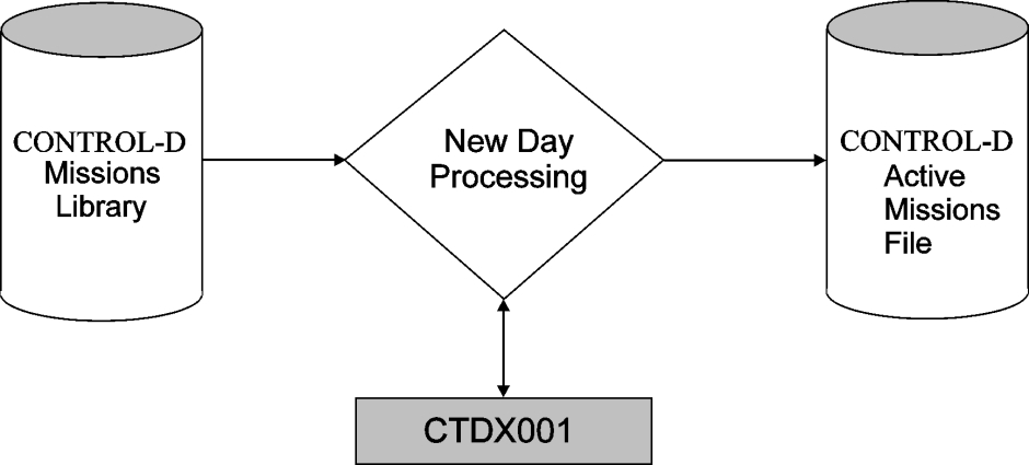
The Active Missions file can contain more than one mission with the same name.
-
Several categories exist for the same printing mission. Consider the organization of bundling by a delivery network. A few categories are used, each category describing a bundle with different report recipients. The categories COURIERNORTH, COURIERSOUTH, COURIERAIRPORT are used for the same printing mission. A different list of recipients are bundled under each category. Using this method, a separate bundle is prepared for each category.
-
A printing mission is late by more than one day (for example, prerequisite reports have not yet finished). In this case, the Active Missions file contains two printing missions with the same name, but each with a different original scheduling date.
-
A daily job is late by more than one day (for example, input tape has not arrived yet). In this case, the Active Missions file contains two report decollating missions for the same job, each with a different original scheduling date.
-
The same job is being run several times a day (see the following figure).
Figure 46 Same Job Run Several Times a Day

Scheduling of decollating missions can depend on the operation mode of the production control system at your site. It is possible to use all the different modes of operation at the same site. This is usually done to solve special scheduling problems.
The different modes of operation generally vary according to the type of production control system in use. The following situations are possible:
-
The production control system is ControlM.
-
The production control system is not ControlM.
-
There is no production control system.
For a description of how Control‑D interacts with production control systems, see Interfaces to Production Control Systems.
Decollation Mission Management
Regular report decollating missions can handle output from the spool or from CDAM datasets. They are executed once to handle the output produced by a specific job name (unless defined as cyclic report decollating missions, with a task type of CRP).
Generic Decollating Missions
Control‑D provides the option of decollating output from dedicated output classes. Whenever a non‑held output exists on the spool in one of the classes defined for generic processing, the Control‑D monitor looks for a generic decollating mission that matches the job name, CLASS, DEST, FORM, and EXTWTR of the selected SYSOUT. The search is performed on all generic missions currently in the Active Missions file, which are not held.
Generic decollation is intended for processing non-standard sysouts (for example, MSGCLASS), or reports generated dynamically from a CICS (or similar) environment. A generic decollating mission can process sysouts from a job that is still running at time of decollation, such as SYSLOG files.
Generic Decollating Mission Workflow
A generic decollating mission can be defined for a specific job name but is usually used in conjunction with a generic job name. A generic job name is specified using mask characters. Execution of the generic decollating mission is triggered by the appearance of a job (whose name matches the job name mask) in a specific output class (in non‑held status). These output classes are defined in the Control‑D installation parameters. The appearance of a matching job name in other output classes (or in held status in the generic classes) does not trigger the execution of a generic decollating mission.
A generic decollating mission can decollate only from the generic classes defined in the Control‑D installation parameters. Any output that is decollated by a generic decollating mission is purged from spool. After decollation, the mission’s postprocessing parameters (OUT, SHOUT) are executed, but the mission does not stay in ENDED status. It is recycled for re‑execution (that is, it is in WAIT SCHEDULE status).
All runtime scheduling criteria (IN, TIME, PRIORITY) are applicable to generic decollating missions. Usually the recycled generic mission is immediately eligible for execution and is assigned the WAITING FOR JOB status.
SYSOUTs of jobs that appear in a generic class but do not have a matching generic decollating mission name in the Active Missions file are removed from the generic class in one of the following ways, depending on the value specified in Control‑D installation parameter GENOTFND:
Table 133 Removal of SYSOUTs of Generic CLass Jobs
|
Value |
Description |
|---|---|
|
Values that are valid under JES2: |
|
|
PRIORITY |
The spool priority of the output is set to one. This allows other output with higher priority to be processed. Default. |
|
DELETE |
The output is deleted from the spool. |
|
HOLD |
The spool status of the output is altered to hold, preventing it from being processed again by Control‑D generic decollation class monitoring. |
|
CLASS=x |
The class of the output is altered to the specified class. This class must not be one of the classes specified in parameter GENCLAS. |
|
Values that are valid under JES3: |
|
|
DELETE |
The output for which there is no associated scheduled generic decollation mission is deleted from the spool. |
|
CLASS=x |
The class of the output is altered to the specified class. This class must be defined as HOLD=EXTWTR. It must not be one of the classes specified in parameter GENCLAS. |
For more information on specifying values for parameter GENOTFND, see the discussion about specifying Control‑D parameters, in the Control‑D chapter of the INCONTROL for z/OS Installation Guide: Installing.
Additional Considerations
It is possible that more than one generic decollating mission matches the same job. In this case, the missions are processed according to their priority levels. If their priorities are equal, they are processed in the order in which they appear in the Active Missions file (that is, in the order in which they were ordered or scheduled).
When GENERIC=Y and MONITOR is blank, the mission is ordered separately for each monitor and each copy of the mission is assigned a different monitor number (ID). This enables concurrent decollating of generic jobs under more than one monitor.
It is also possible that a match may occur between a generic definition and a regular report decollating mission. This duplication should not create problems, because it is impossible to specify a generic class in an ON CLASS statement of a regular report decollating mission. However, if a regular (ON DSN) report decollating mission is specified with parameter WHEN IN QUEUE=Y, it may never execute, because its job’s output is deleted by a generic decollating mission. If WHEN IN QUEUE=Y is specified for a regular report decollating mission, make sure that the job’s output is not deleted by a generic mission.
In an environment using a production control system there is a significant advantage in decollating job reports using regular report decollating missions. The decollating of the reports can be made dependent on a prerequisite condition that is added by the production control system after checking that the job has finished executing OK. Using this method, erroneous reports are not decollated. On the other hand, MSGCLASS output of the job (on another class) is best handled by a generic decollating mission.
For example, generic decollating missions can be used to
-
handle all MSGCLASS outputs of jobs in the same way (for example, move them from spool to compressed datasets, allow Online Viewing of output, and retain backups for two weeks)
-
handle single purpose jobs (for example, decollate output to users based on job prefix)
Control‑D first handles regular report decollating missions according to their priority and then scans the generic output classes for outputs. However, this does not guarantee that the regular mission of the same job is executed before a generic one.
Scheduling Generic Decollating Missions Through the New Day Procedure
Special scheduling of generic decollating missions ensures that all generic missions are scheduled successfully before the Control‑D monitor starts generic mission processing. If procedure CTDNDAY fails (for example, the system crashes or there are invalid parameters in generic decollating mission definitions) while processing a report decollating mission from member GENLIST, when the Control‑D monitor is started, it does not process generic decollating missions without a manual operator command. If all generic missions are scheduled successfully, decollating of generic missions resumes when the Control‑D monitor is brought up.
If generic mission decollating is not active when the Control‑D monitor shuts down for a new day (for example, because the operator deactivated it manually), it remains inactive when the Control‑D monitor is brought up again.
Generic decollating missions can also be scheduled manually, or by any of the other scheduling methods. However, it is highly recommended not to schedule the missions through the REPLIST member of the New Day procedure with non‑generic decollating missions.
Controlling the Generic Process
You can control generic processing by turning it off and on. This process is performed through operator commands. By default, generic processing is started when Control‑D is started (unless it was previously deactivated by an operator command).
One reason that generic processing may be deactivated is if the Control‑D New Day procedure (CTDNDAY) fails to schedule the generic missions to the Active Missions file. When generic processing is deactivated, the generic missions do not select output from the defined generic classes.
Generic processing may also be deactivated if an error occurs while updating the Active User file during decollation. In this case generic processing is deactivated to prevent the deletion of sysouts from the spool without the creation of relevant reports in the Active User file.
To stop generic processing, issue the following operator command:
F CONTROLD,STOPGENTo start generic processing, issue the following operator command:
F CONTROLD,STARTGENDefining a Generic User Name List
Control‑D provides an option to specify a generic user name in the report decollation definition. For a detailed description, see the DO USER parameter in the Control‑D and Control‑V User Guide. This option defines a generic name that describes a group of users (for example, all the branches of the bank, senior management, or financial controllers).
A generic user name list resides in a PDS member. The name of the member is referenced in the DO USER statement, preceded by an asterisk (for example, *BRANCHES). The member must be in a library referenced by DD statement DAGENUSR of the User Daily job (or CTDNDAY). Although, it is possible to use a few generic user name libraries in a distributed environment, it is generally recommended that you use only one to simplify the administration.
Each member in the library represents a generic user name. The contents of the member are lines in the following format:
-
column 01 to 05 – TUSER (that is, constant value TUSER)
-
column 06 to 09 – blank
-
column 10 to 11 – level code of the user (for example, recipient) as defined in the Recipient Tree
-
column 12 to 31 – user name
One line is required for each user. Additional lines in the member are not permitted. Do not use columns 73 to 80. Each line must describe a valid user name in the Recipient Tree. Use the main user name, not a synonym.
The following is an example of the member BRANCHES:
TUSER  30BR101
TUSER  30BR103
TUSER  30BR106
TUSER  30BR112
TUSER  30BR114
TUSER  30BR123
TUSER  30BR127
TUSER  30BR128
TUSER  30BR130
Decollating from an IBM WebSphere® MQ Queue
Decollation missions that process IBM WebSphere MQ Queue messages work in essentially the same way as generic decollation missions—an MQ decollation mission is placed in the Active Missions File during ordering, and remains in active status. The mission is then selected by the Control‑D monitor when a message from the corresponding MQ queue is available.
MQ messages can be identified by the MQ Queue name in the message header, and by the MQ selection criteria contained in ON MQ statements. For additional information, see the discussion of the MQ and ON MQ parameters in the Control‑D and Control-V User Guide.
For proper decollation from an IBM WebSphere MQ queue, WebSphere MQ for z/OS must be active on the LPAR where Control-D monitors run.
Concatenating Required Libraries
Before using MQSeries support in Control‑D, the following libraries must be concatenated to the STEPLIB in the IOAENV member of the IOA PROCLIB library:
Table 134 Libraries to be Concatenated Before Using MQSeries Support
|
Library |
Description |
|---|---|
|
All concatenated libraries must be APF authorized. |
|
|
prefix.SCSQANLx |
This library (where x is the language letter indicator for your national language), must be concatenated before the prefix.SCSQAUTH library in either the STEPLIB DD statement, the JOBLIB, or the LINK LIST. |
|
prefix.SCSQAUTH |
Main repository for all MQSeries product load modules. The library also contains the SCQZPARM and CSQXPARM default parameter modules. |
|
prefix.SCSQLOAD |
Load library. The library contains load modules for non‑APF code, user exits, utilities, samples, installation verification programs, and adapter stubs. |
Starting and Stopping MQ Decollation Missions
By default, the MQ Series decollation process begins when Control-D is started. Users can toggle MQ Series decollation off and on through operator commands.
Decollation processing from the MQ Queue might be deactivated if an error occurs while updating the Active User file during decollation. In this case the processing is deactivated to prevent moving messages to the Escape MQ Queue without the creation of relevant reports in the Active user file.
The process might also be deactivated, if decollation 'ENDED NOT OK' and relevant (special) error messages occur.
To stop processing decollation from MQ Series issue the following operator command:
F CONTROLD,STOPMQTo start processing decollation from MQ Series issue the following operator command:
F CONTROLD,STARTMQHow MQ Decollation Missions are Processed
Decollation missions are processed as follows:
-
During initialization of MQ decollating missions the ControlD monitor creates a special MQN table. The MQN table, which functions similarly to the GENCLASS list from the CTDPARM library, contains all MQ queue names from the MQ decollation mission definitions.
-
The ControlD monitor looks through the MQN table and checks each MQ queue name in the table for a message in the corresponding queue. If a message is not found, the ControlD monitor checks for the next MQ name in the MQN table.
If several Control-D monitors are configured to process the same MQ queue, Control-D needs a synchronization mechanism to avoid having different Control-D monitor processing the same MQ message. For this purpose, the first monitor accessing the MQ queue has exclusive access to it. Until the queue is closed, only that monitor can remove or browse messages from it. After the queue is closed, the MQ queue is accessible to other monitors.
-
As soon as a message is found in a queue, the ControlD monitor checks all ONMQ statements of the MQ decollation missions against the descriptor of the received MQ message. If no appropriate mission is found, the message is moved to the MQ escape queue, which is defined in the CTDMQPRM member by the MQNOTFIND parameter. (CTDMQPRM Parameters.) If there are several MQ decollation mission definitions with the same ONMQ selection criteria in the Active Missions File, only the first one with the highest priority will process the received message.
-
A decollation mission begins to work from the selected message if the ONMQ statement matches the descriptor of the MQ message. After the message is processed, Control-D tries to read the next message from the same MQ queue and checks it against the current decollation mission. If the next selected message does not match any ON statement of the current decollation mission, this decollation mission terminates and the Control-D monitor returns to check the next message in queue in the MQN table. The next cycle of MQ message processing will begin after the last rejected message.
-
If no appropriate MQ decollation mission is found for selected message, it's moved to special MQ queue defined in MQNOTFIND parameter.
The number of messages that can be processed in one cycle by the same decollation mission is limited by the MAX MSG parameter in the decollation mission definition. The maximum number of cycles is defined by Optional Wish WD2012 (the default is 8).
How MQ Messages are processed
MQ messages are processed as follows:
-
Messages processed by the decollation mission are deleted from the queue during the mission termination process, after the corresponding CDAM files, USER, and SYSDATA records are created.
-
Each message selected from the MQ queue is treated as a separate sysout that is selected from the JES spool. This enables the placement of each message in a separate CDAM file, or the placement of an accumulation of messages in JOBSDSN1 and JOBSDSN2 CDAMs.
Processed messages are split into lines in the following manner:
-
Binary messages are processed into 32K lines.
-
Text messages are processed according to the new line character (NL, CR/LF, LF, CR/NL).
Messages are considered to be text messages if the FORMAT field contains the MQFMT_STRING value.
CTDMQPRM Parameters
The CTDMQPRM member contains the following parameters:
Table 135 CTDMQPRM Parameters
|
Parameter |
Description |
|---|---|
|
MQMANAGER |
Name of the MQ Manager that works with the Control‑D monitor |
|
MQNOTFIND |
Name of the MQ queue where MQ messages will be moved if there are no decollation missions in the Active Mission File that match the MQ message name |
|
MQCONFIRM |
Name of the MQ queue where confirmation messages should be sent |
Interfaces to Production Control Systems
Various aspects of Control‑D/Production Control System interfaces are explained in the following topics:
-
overview of ControlM scheduling with ControlD
-
scheduling through the ControlM production control system
-
scheduling through a production control system other than ControlM
Overview of Control-M Scheduling With Control-D
Control‑M jobs are scheduled and placed in the Active Jobs file during Control‑M New Day Processing. (The job order is submitted when the runtime requirements are satisfied.) The main function of Control‑M New Day Processing is to determine whether to execute the job on a specific day. Once that decision is made, the job order is placed in the Control‑M Active Jobs file.
The Control‑D category field in the Control‑M job order is checked. If the category field is not blank, the library referenced by DD statement DAREPMIS is searched for the appropriate report decollating mission. The library is searched for a member with the same name as the Control‑M MEMNAME parameter (the Control‑D job name), and for the same category as specified in the Control‑M category field. If category * was used, the library is searched for all categories of the specified job name.
In this case, the scheduling criteria of the Control‑D report decollating missions (if any) are ignored. Note that if the CTGFORC parameter of the CTMPARM member in the IOA PARM library is set to NO, selected categories are scheduled (that is, not forced). Report decollating mission parameters are passed to Control‑D User Exit CTDX001. This exit may alter the contents of the parameters or cancel the decollating mission. If the report decollating mission is not cancelled by the exit, the report decollating mission is placed in the Control‑D Active Missions file. The original scheduling date assigned to the report decollating mission is the same as that of the Control‑M job order.
The following figure shows Control‑M Scheduling with Control‑D:
Figure 47 Control-M Scheduling with Control-D
Usage Instructions
The library containing report decollating mission definitions is referenced by DD statement DAREPMIS. This DD statement is normally included in the Control‑M User Daily job. However, if jobs ordered through the New Day procedure have decollating missions, DD statement DAREPMIS must also be included in the Control‑M New Day procedure. Add DD statement DAREPMIS wherever it may be needed, for example, to procedures/batch utilities CTMTDAY, CTMDAILY, CTMJOBPR, CTMAPI, CTMJOB, the CLIST CTMCJOBS, the Online monitor, KSLs which perform ordering functions and so on.
More than one partitioned dataset can be referenced by each DD statement DAREPMIS (in a job or CLIST). If a library is not referenced, an error message is produced and the Control‑M New Day procedure or the User Daily job skips to the next job.
If you want to use more than one library to store definitions of report decollating missions, more than one Control‑M Daily can be used. This usually corresponds with using more than one Control‑M scheduling library (for security reasons).
Relevant DD Statements Only
Control-M User Daily Job 1
//USER01     EXEC  CTMDAILY
//DACHK      DD    DISP=SHR,DSN=parm‑library‑1(date‑Control‑record‑1)
//DAJOB      DD    DISP=SHR,DSN=scheduling‑library‑1(table‑1)
//           DD    DISP=SHR,DSN=scheduling‑library‑1(table‑2)
//           DD    DISP=SHR,DSN=scheduling‑library‑1(table‑3)
//DAREPMIS   DD    DISP=SHR,DSN=report‑definitions‑library‑1
//DAAMF      DD    DISP=SHR,DSN=the‑Control‑D‑active‑missions‑file
Control-M User Daily Job 2
//USER02     EXEC  CTMDAILY
//DACHK      DD    DISP=SHR,DSN=parm‑library‑2(date‑Control‑record‑2)
//DAJOB      DD    DISP=SHR,DSN=scheduling‑library‑2(table‑1)
//           DD    DISP=SHR,DSN=scheduling‑library‑2(table‑2)
//DAREPMIS   DD    DISP=SHR,DSN=report‑definitions‑library‑2
//DAAMF      DD    DISP=SHR,DSN=the‑Control‑D‑active‑missions‑file
For a full description of Control‑M New Day processing, see Control-M.
Job-Report Dependency
It is recommended that you establish dependency between the successful execution of the job under Control‑M and the processing of the job’s reports by the Control‑D report decollating mission. The dependency can be established using a prerequisite condition. Parameter OUT of the job order under Control‑M must specify a prerequisite condition to be referenced by parameter IN of the Control‑D report decollating mission.
The following figure shows a Job-Report dependency:
Figure 48 Job-Report Dependency
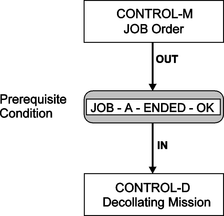
Using Control-M Scheduling Data – Summary
The advantage of invoking the Control‑D report decollating missions through Control‑M scheduling criteria is that the scheduling criteria only have to be defined once (under Control‑M). It is then unnecessary to update the scheduling criteria of Control‑D each time the criteria are updated in Control‑M. In addition, job orders under Control‑M can automatically place report decollating missions in the Control‑D Active Missions file.
The job scheduling information is managed by one source of data and control.
Scheduling Through the Control-M Production Control System
When the Control‑M production control system is in use, the integrated environment of Control‑D and Control‑M can produce optimum results.
In such an environment, the recommended method of scheduling a non‑generic report decollating mission is through Control‑M scheduling criteria.
The Control‑M Job Scheduling Definition screen contains a field (D-CAT) to indicate that a Control‑D report decollating mission must be scheduled whenever the job is scheduled to run under Control‑M.
In this field, the user specifies the Control‑D category of the report decollating mission that musty be selected from the Control‑D report decollating mission library. To select all categories of the job, specify an asterisk (*) in the D-CAT field. (If the D-CAT field is empty, a report decollating mission is not scheduled for the job.)
Each report decollating mission can be composed of a few categories. The category is usually used as a mechanism to specify different report decollating (processing) parameters for different execution days (for example, a regular work day, end of the month).
Based on different scheduling criteria under the Control‑M monitor, the same Control‑M job order can be used to select different report decollating missions of different categories.
Figure 49 Control-M Job Order Used to Select Different Report Decollating Missions
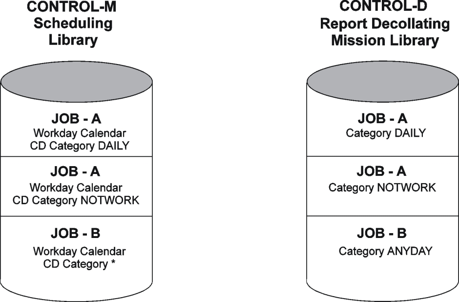
Operating Control‑M and Control‑D together in the same environment may cause the following situations:
-
A job to be run by ControlM does not generate any reports. Therefore, there is no need to process the job by ControlD. In this case, the category field in the ControlM Job Scheduling Definition screen must remain blank.
-
A job to be run by ControlM generates a report but does not yet have a report decollating mission defined for the job. (ControlD can be implemented in phases.) In this case, the category field in the ControlM Job Scheduling Definition screen must remain blank.
-
A job generates a report that must be decollated by a ControlD report decollating mission. In this case, the name of the ControlD category of the report decollating mission must be defined in the D-CAT field in the ControlM job scheduling definition. An asterisk (*) can be used to select all categories of the job.
Scheduling Through a Non-Control-M Production Control System
The primary advantage of invoking Control‑D report decollating missions from the user exit of a production control system is that scheduling criteria only have to be defined once (under the production control system). The user does not have to update scheduling criteria of report decollating missions each time they are updated in the production control system.
The following methods can be used to implement Control‑D in data centers that use a production control system other than Control‑M:
-
ControlD scheduling is managed independently of the production control system. This method is the same as managing the scheduling without any production control system.
-
The scheduling of report decollating missions under ControlD is controlled by the production control system (described in the following paragraphs).
Most production control systems include some means of passing control to a user exit before a job is submitted. Some products have user exits in earlier stages (when the decision to schedule a job for a specific day is made). The basic idea is to invoke the Control‑D report decollating mission from the user exit of the production control system.
Operating a production control system and Control‑D together in the same environment may cause the following situations:
-
A job that is to be run by the production control system does not have any reports. It does not need to be processed by ControlD.
-
A job that is to be run by the production control system does not yet have a report decollating mission defined for the job.
-
A job is to be run by the production control system and decollated by ControlD.
To handle the situations mentioned above, the user must use some method of specifying to the production control system user exit whether to issue a report decollating mission for the job. The decision of how to mark a job is local for each installation and can be performed using one of the following methods:
-
Specify a flag in a job scheduling parameter of the production control system that is otherwise unused, or is used for another purpose (for example, the job description).
-
Use a list accessed by or internal to the user exit. The list must be modified whenever a new report decollating mission is defined.
When the production control system user exit receives control and a decision is made to invoke a report decollating mission, the user exit must activate program CTDRRQ. This program performs a search for the report decollating mission. For more information about program CTDRRQ and its parameters, see Programs Called During New Day Processing.
The search is made for a member name with the same name as the job name and for the specified category. The scheduling criteria of the Control‑D report decollating mission (if any) are ignored. The report decollating mission parameters are passed to Control‑D User Exit CTDX001. This exit can alter the contents of the decollating parameters or cancel the decollating mission. If the report decollating mission is not cancelled by the exit, it is placed in the Control‑D Active Missions file.
Usage Notes
When a report decollating mission is scheduled by invoking program CTDRRQ from a production control system user exit, the following DD statements must be used:
-
STEPLIB – IOA LOAD library (if not included in the MVS Linklist)
-
DAAMF – ControlD Active Missions file
-
DAOUT – Output print file
-
DALOG – IOA Log file
-
DAGENUSR – Generic user names library (if this option is used at yoursite)
If the production control system does not have an appropriate exit or you do not want to use this method to schedule report decollating missions, there is an alternative. Most production control systems can produce a night plan report – a list of jobs to be executed during the night. This list can be used as input to a program that schedules report decollating missions by invoking program CTDRRQ.
The IOA SAMPLE library contains examples of production control system interfaces. Member $$INTER in the IOA SAMPLE library contains an index to these interfaces. A user‑written interface to CA‑7 (UCC7) is not officially supported but is available. For more information about the CA‑7 (UCC7) interface and interfaces to other production control systems contact BMC Customer Support.
Job–Report Dependency
It is recommended that you establish dependency between the successful execution of the job under the production control system and the processing of the job’s reports by the Control‑D report decollating mission. This dependency can be established using the prerequisite condition concept.
A prerequisite condition (for example, REP‑M01AUPD‑READY) must be specified in the IN parameter of the Control‑D report decollating mission. This condition is added to the IOA Conditions file by the production control system after the job finishes executing successfully.
Use utility IOACND to add a prerequisite condition. This utility can be activated from
-
a production control system user exit
-
a specially defined successor task of the job under the production control system
-
a job step.
It is not mandatory to establish through dependency prerequisite conditions between the production control system and Control‑D. If dependency is not established, Control‑D processes the reports when the job enters the output queue. It is also possible to use manual prerequisite conditions for report processing when required.
Considerations for when Control-M and Control-D are installed
The following issues must be considered if both Control‑M and Control‑D are being installed:
-
When both ControlM and ControlD are installed, IOA installation parameter CTM must be set to Y (Yes). When CTM=Y, maintenance of conditions in the Conditions file is handled by the ControlM New Day procedure and not by ControlD. Therefore, it is recommended that the ControlM New Day procedure always run before the ControlD New Day procedure. The ControlM New Day procedure CTMTDAY must delete all conditions from the previous year. The ControlM New Day procedure can receive parameters that control the delete operation through DD statement DAFRMIN.
-
You should clean the IOA Conditions file periodically using utility IOACLCND. Use only utility IOACLCND to clean the IOA Conditions because this file is used for both Control-M and Control-D. Use DD statement DACRSIN to assign the parameter control member.
-
Utility IOALDNRS builds the Manual Conditions file from information in the ControlM Active Jobs file, the ControlD Active Missions file, and the IOA Conditions and ControlM Resources files. However, the CTDLDNRS utility, which perform the same function, is supplied for compatibility with previous versions of ControlD. The CTDNDAY procedure includes the CTDLDNRS step, which performs the same function after the Control-D missions are ordered.
After any massive ordering of Control-M jobs or Control-D missions (including the Control-M and Control-D New Day procedures), the Manual Conditions file—common to Control-M and Control-D—must be rebuilt. To rebuild the Manual Conditions file, use either the IOALDNRS utility or the CTDLDNRS step. To assign the parameter control member, use DD statement DALNRIN.
If the Control-D and Control-M New Day procedures start at the same time, you need to ensure that both procedures finish before running the IOALDNRS utility or the CTDLDNRS step. Use one of the following options:
-
Set Control-D New Day time (DAYTIMED) long enough after Control-M New Day time (DAYTIME) to ensure that Control-M New Day is ended.
-
Remove the CTDLDNRS step from the CTDNDAY procedure. Run the IOALDNRS utility after both Control-M and Control-D New Day procedures have finished.
-
Printing Mission Management
This section discusses the following topics:
-
printing mission workflow
-
printing mission definition
-
preparing the skeleton
-
-
advanced scheduling issues
-
distribution according to scheduling dates
-
report decollating and printing mission dependency
-
-
printer control
-
onechunk method
-
multichunk method
-
oneoutgroup method (JES2 only)
-
opening and closing printers
-
printing process
-
-
identifying ControlD chunks on spool (JES2 only)
-
printing on AFP (APA) printers
-
printing using XEROX LCD5 (DJDE) parameters
-
using OUTPARMS for global control of printing characteristics
-
printing to a file
-
tailoring exit CTDX005
-
-
advanced ACIF interface facility
-
Advanced Function Presentation Data Stream (AFPDS)
and AFP Conversion and Indexing Facility (ACIF) -
ACIF utility benefits
-
making ACIF accessible to ControlD
-
activating the advanced ACIF interface
-
Printing Mission Workflow
Printing Mission Definition
The following table describes the parameters (specified in the Online facility) that affect printing mission workflow:
Table 136 Parameters Affecting Printing Mission Workflow
|
Parameter |
Description |
|---|---|
|
BATCH |
Specifies whether a printing mission is submitted as a batch job or as a subtask of a Printers Control monitor. Optional. Y (Yes) - Submit the current printing mission as a batch job instead of executing it as a subtask of the Printers Control monitor. N (No) - Execute the printing mission as a subtask of the Printers Control monitor. Default. |
|
SKELETON |
Name of an existing member in the Control‑D SKL library. This member contains the job skeleton or started task skeleton for the batch job. Mandatory if BATCH is set to Y (Yes). |
|
FREE |
SYSOUT allocation mode. Determines whether chunking is implemented and when SYSOUT files are freed. Optional. Valid values: CLOSE - Regular chunking mechanism is used. SYSOUT files are freed as soon as they are printed. Default. END - SYSOUT files are allocated as usual but are not freed until the end of the batch job. This value is available only if BATCH=Y is specified. |
|
TIMEOUT |
mm - Number of minutes within which the printing mission must start. If the mission does not start during the specified time interval, it terminates NOTOK. Default: 5 minutes. |
For more information about these parameters, see the Control-D and Control-V User Guide.
The defined printing missions are stored in the Print Mission library.
The following figure illustrates the steps of Printing Mission workflow from initial scheduling of the printing mission through the printing of reports:
Figure 50 Printing Mission Workflow
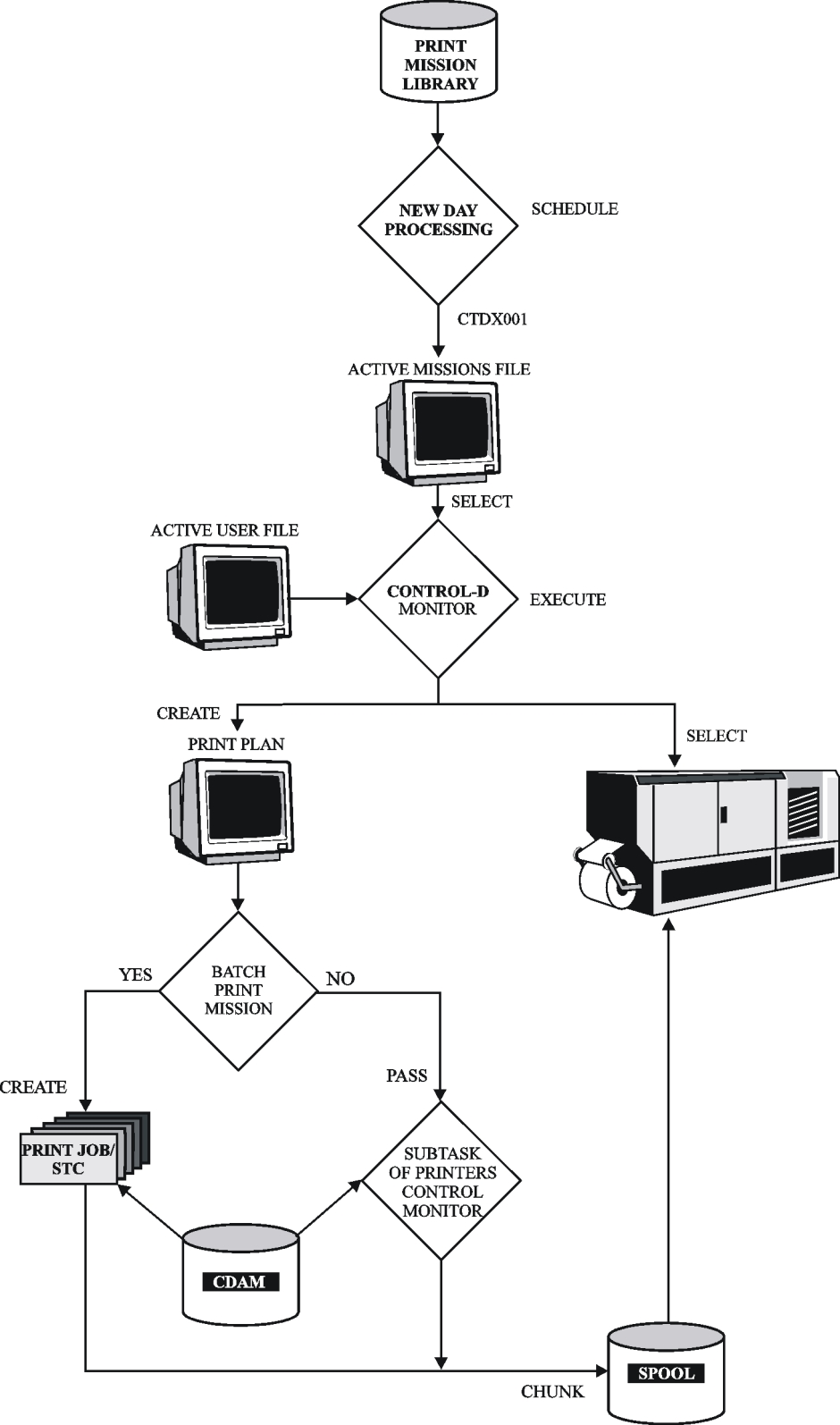
A printing mission is executed as follows:
-
The ControlD monitor makes a fast scan of the Active User file to locate all reports that require printing by the specified printing mission. The result of this process is a Print Plan file with an entry for each report to be printed.
-
In addition, the ControlD monitor selects an available logical printer for this printing mission. When the printer is selected, control is passed to the Printers Control monitor (CTDPRINT) if parameter BATCH was set to N (No), or to a batch job if parameter BATCH was set to Y (Yes).
Chunks are sent to the spool according to the value specified for parameters CHUNKSIZE and OVERRIDE. For further details, see Printer Control
After printing is completed, the status of each report entry from the Print Plan file is updated in the Active User Report List file according to the printing completion status (for example, Printed or Not printed).
Processing a Batch Printing Mission
When the report is printed by a batch job, the Control‑D monitor reads the member whose name is specified in the printing mission (for example, PRTSKL) from the library referenced by DD statement DADSKL of the Control‑D monitor. This member contains a job skeleton or started task skeleton for the batch job.
Because the same library is used for printing, migration, backup and restore mission skeletons, the names of all missions must be unique.
Preparing the Skeleton
To use a printing mission in batch mode, a skeleton member must be prepared in the Control‑D SKL library. The skeleton member can be either a job skeleton or a started task skeleton. For more information, see sample member PRTSKL in the Control‑D SKL library.
The skeleton member can contain parameters that are interpreted by the Control‑D monitor. The following table describes these parameters:
Table 137 Skeleton Member Parameters
|
Parameter |
Description |
|---|---|
|
%COM#% |
Number of the COM file record assigned to this mission. |
|
%MISSION% |
Mission name. |
|
%CATEGORY% |
Mission category. |
|
%GROUP% |
Mission group. |
|
%OWNER% |
Mission owner ID. |
|
%PRTY% |
Mission priority. |
|
%DEST% |
Mission destination first specification. |
|
%UDEST% |
Mission destination second specification |
When Control‑D finishes preparing the member for submission, control is passed to User Exit CTDX009. This exit can modify the contents of the submitted job (by adding, deleting or modifying the JCL). The exit can return the return codes described in the following table:
Table 138 Return Codes for Exit CTDX009
|
Return Code |
Description |
|---|---|
|
0 |
Submit the job. |
|
4 |
Do not submit the job. User Exit CTDX009 can request Control‑M to submit the job. Job submission can be done through CTMAJO routines to ensure correct handling of the print job under Control‑M. |
|
8 |
Do not submit the job. Terminate the mission with NOTOK status. |
Synchronization between the printing mission and the Control‑D monitor is achieved by creating a special control subtask for each printing mission in the Control‑D address space. (The same method is used to synchronize the Control‑D and Printers Control monitors.) This control subtask is synchronized with the corresponding print task through the ENQ mechanism. The QNAME for this ENQ is taken from Control‑D installation parameter PRTSTC in member CTDPARM in the IOA PARM library.
To run a batch printing mission on a CPU other than the CPU in which the Control‑D monitor runs, this QNAME must be shared through GRS, MIM, or other enqueue manager products.
If parameter PRTMON# is set to 0 in member CTDPARM, no Printers Control monitors are started. In this case, parameter BATCH in the printing mission must be set to Y (Yes).
For additional considerations on running printing missions in batch mode, see One-Outgroup Method (JES2 Only).
Printing mission abend or timeout does not cause termination of Control‑D monitors. In such cases, the printing mission terminates with a status of NOTOK.
Advanced Scheduling Issues
Distribution According to Scheduling Dates
It is possible to organize printing missions so that each day’s printing management (that is, the printing workflow) is the same. The simplest method is to specify DAYS=ALL in the Basic Scheduling parameters of all printing missions. Once a day, when the New Day procedure calls program CTDPRQ, all printing missions scheduled for the next 24 hours are placed in the Active Missions file.
This printing organization does not maximize the capabilities of Control‑D. You can organize the printing order in different ways for different types of days (for example, weekdays, weekends, end of the month, holidays).
Using Control‑D, it is possible to define several copies of the same printing mission. Each copy is an independent definition of the printing mission and can have different scheduling criteria, different runtime criteria, different bundling instructions, different printing configurations, and so on. For example, the (form) STD printing mission does not start later than 05:00 on every workday, does not start later than 04:00 at the end of the month, and is not scheduled for holidays.
Since there is no limit to the number of printing missions that can be defined, the user can organize the printing process to optimally suit every production day of the year.
Report Decollating and Printing Mission Dependency
We recommend that the printing of bundles by Control‑D printing missions depend upon the successful decollation of reports. Dependency can be established using the prerequisite condition concept. Parameter OUT of the report decollating mission must specify a prerequisite condition that is referenced by parameter IN of the printing mission. Using this method, bundles start printing only when all the reports that must be included in them have been decollated.
It is possible to define different report‑printing dependencies for different scheduling dates (for example, regular dates vs. end of the month). This can be done by using multiple copies of the same printing mission, each one distinguished by different basic scheduling criteria and different runtime scheduling criteria (prerequisite conditions, time, priority, and so on).
Printer Control
The following table describes the methods that Control‑D provides for printing bundles:
Table 139 Methods for Printing Bundles
|
Method |
Description |
|---|---|
|
One‑Chunk Method |
Send entire bundle to the spool for printing. |
|
Multi‑Chunk Method |
Send a specified number of lines at a time to the spool for printing. |
|
One‑Outgroup Method |
Send one outgroup (containing all output files produced by a printing mission) at the end of that printing mission. |
One-Chunk Method
Using this method, the entire bundle is sent to the spool for printing at one time. This method is activated by specifying CHUNKSIZE=0 in the printing mission definition. If not specified in the printing mission definition, CHUNKSIZE defaults to the value defined in installation parameter PRINTER. Specifying CHUNKSIZE=0 suppresses installation parameter OUTGRP.
This method can be used for printing reports that contain identical printing characteristics. If reports that contain different printing characteristics are processed in this manner, the characteristics of the first report are used for all the reports in the bundle.
If the bundle contains reports for different printing destinations, a separate chunk is created for each destination but Control‑D does not monitor the printing of the chunk. Control‑D continues to send additional chunks of the bundle to the spool.
Multi-Chunk Method
Control‑D creates a new chunk each time the number of lines specified in the CHUNKSIZE parameter is exceeded, or when printing characteristics of the reports change, whichever comes first (unless CHUNKSIZE is specified as "0" as described in "One‑Chunk Method"). CHUNKSIZE can be specified in the printing mission definition. If it is not specified in the printing mission definition, CHUNKSIZE defaults to the value defined during the installation process.
For the Multi‑Chunk method, the value for the CHUNKSIZE parameter must be greater than 1. The recommended value is 10000. If the CHUNKSIZE parameter is set to 999999, a new chunk will be created only if at least one of the printing parameters is changed. In this case an entire report will be issued to the same chunk.
Multi‑Chunk processing provides the following major advantages:
-
the ability to print reports with different printing characteristics in the same bundle
-
the ability to control the size of the chunk so the spool does not become overloaded
Under the Multi‑Chunk method, the printer must be assigned to Control‑D using the following JES commands.
Under JES2
A printer is normally defined as DEST=LOCAL with one or more printing classes. To assign the printer to Control‑D, use a JES operator command to initialize the printer with the parameters described in the following table:
Table 140 JES2 Printer Initialization Parameters
|
Parameter |
Description |
|---|---|
|
S=N |
No separator (because Control‑D creates its own banner pages). |
|
R=destination |
This value is set during Control‑D installation for each printer. |
|
SEPDS=N |
No dataset separator. |
|
WS=-Q |
Select from all output classes on which Control‑D can print. |
The following is a sample JES2 operator command:
$TPRT1,S=N,R=U1001,SEPDS=N,WS=(‑W,‑Q,‑PRM,‑LIM/R,‑F,‑UCS,‑FCB)Verify that the printer has been modified successfully with all the above attributes.
Under JES3
Change the printer options using an operator command. Initialize the printer with the parameters described in the following table:
Table 141 JES3 Printer Initialization Parameters
|
Parameter |
Description |
|---|---|
|
B=N |
No burst separator because Control‑D creates its own banner pages. |
|
WC=class |
The class defined in Control‑D installation parameter PRINTCL. |
The following are sample JES3 operator commands (PRINTCL=Z):
*CALL WTR,OUT=04E,H=N,B=N,WC=Z,WS=CL
*S 04E
where * is the JES3 command prefix.
Verify that the printer has been modified successfully with all the above attributes.
One-Outgroup Method (JES2 Only)
It is possible to combine all the output files produced by a printing mission in one output group. Such a method is useful to ensure that all files are printed together even if the JES printer is not dedicated to Control‑D and is used for other jobs as well as for Control‑D reports. This method is also useful for output files that are sent through NJE to a remote computer.
To combine the output files, perform the following steps:
-
Run the printing mission as a batch job. (Set parameter BATCH to Y (Yes) in the Printing Mission Definition screen.)
-
Free all sysout files at the end of the job. (Set parameter FREE to END in the Printing Mission Definition screen.)
Note the following:
-
The CLASS, DEST, WTRNAME, PRMODE, and OUTGROUP parameters must be the same for all reports included in the printing mission.
-
The OVERRIDE parameter in the Printing Mission Definition screen can be used to assign uniform values to parameters CLASS, DEST and WTRNAME.
-
The PRMODE=PAGE and GROUPID=CONTROLD parameters must be defined in all OUTPUT statements in the Printers Control monitor JCL procedure (CTDPRINT).
-
-
Set the USERSET parameter to YES in the OUTDEF statement in the JES2PARM member in the SYS1.PARMLIB library.
-
Verify that the output class is a nonheld class.
Opening and Closing Printers
During installation, a value of OPEN or CLOSE is assigned to parameter PRINTER for each printer. If installation parameter PRINTER is set to OPEN for a printer, it is not necessary to "open" that printer unless it has been "closed" by an operator command.
-
To display the entire list of open printers, issue operator command
CopyF CONTROLD,STARTPRTIf a required printer was defined as CLOSE, issue the following operator command to "open" it:
CopyF CONTROLD,STARTPRT,printernamewhere printername is the name assigned to the printer during ControlD installation.
The following message is displayed on the operator console from which the operator command was issued:
CTD130I COMMAND "STARTPRT" ACCEPTED FOR PRINTER printername
-
To "close" a ControlD printer, issue operator command
CopyF CONTROLD,STOPPRT,printernameWhen there are no ControlD bundles to print, you can reset the printer’s original parameters with a JES command.
It is not necessary to "close" Control‑D printers. A printer remains "open" but nothing is printed if the JES2‑DEST or JES3‑CLASS setting of the printer is not assigned to Control‑D.
Printing Process
When a printing mission is activated manually or automatically, the printing mission creates an index of all reports that are ready to print and that were specified to be printed by this particular printing mission. This index can be viewed and controlled online using the Print Control option (P) in the Active Missions screen. The bundle is then prepared for printing.
Control‑D searches for an available printer that was defined in parameter PRINTER of the printing mission definition. If parameter PRINTER has not been specified, Control‑D searches for any available printer that was defined in installation parameter PRINTER.
If a printer was defined as CLOSE, an operator command is required to OPEN the printer. For details, see Opening and Closing Printers. If a printer was defined as OPEN or if an operator command was issued to "open" it, Control‑D sends the bundle to the spool for printing.
When using the One‑Chunk method, the full bundle is created on the spool and waits in queue to print (along with any other output that may be on the spool—that is, non‑Control‑D output).
When using the Multi‑Chunk method, it is recommended that you send only Control‑D bundles to the printer at a specified time. If the printer is not assigned exclusively to Control‑D when using the Multi‑Chunk method, non‑Control‑D output may be printed in a Control‑D bundle. After the bundles finish printing, the printer can be assigned to print non‑Control‑D output.
Bundle printing can be interrupted using the Print Control option in the Active Missions Status screen. This may be required to immediately print an important non‑Control‑D output, to change priority of a report printed by Control‑D, or to perform any other desired action during the printing process. For a description of this option, see the online facilities chapter in the Control‑D and Control‑V User Guide.
Identifying Control-D Chunks on Spool (JES2 Only)
Control‑D provides the ability to uniquely identify each chunk that is sent to the JES output queue. This is done by appropriately setting the OUTGROUP field (GROUPID in JCL, O‑GRP‑N in SDSF) for the chunks that Control‑D sends to the spool.
Control‑D can place the following types of identifiers in the OUTGROUP field:
-
original job name of the report
-
user name of the user (for example, recipient) who is to receive the report
-
printing mission name
-
unique time stamp
-
specific string specified in the printing mission
To activate this feature, do the following:
-
Add a special OUTPUT statement to the ControlD Printers Control monitor procedure (CTDPRINT). It must be coded as follows:
Copy//OUTGROUP OUTPUT GROUPID=CONTROLDIf the site runs more than one Printers Control monitor (CTDPRIN2, and so on), add this DD statement to all the Printers Control monitor procedures.
-
Add operand GROUPID=CONTROLD to all OUTPUT statements in the Printers Control monitor procedures. This operand must be coded in the first operand in the OUTPUT statements.
-
Set the OUTGRP ControlD installation parameter in member CTDPARM in the IOA PARM library, as detailed in the INCONTROL for z/OS Installation Guide: Installing.
We recommend specifying OUTGRP=Y, and using the GROUP parameter in the printing mission definition to define OUTGROUP processing. For information about using the GROUP parameter, see the chapter that discusses printing mission parameters in the ControlD and ControlV User Guide.
Printing on AFP (APA) Printers
AFP (Advanced Function Printing presentation) is the standard IBM laser printing technology that supports printers such as the 39xx and 38xx family of printers, and uses APA (All Points Addressable) technology. Throughout this guide and in the Control‑D and Control‑V User Guide, these printers are referred to as AFP printers. The way in which Control‑D supports AFP printers is described. For additional information, including instructions for customizing, see the INCONTROL for z/OS Installation Guide: Installing and the publication, Implementing AFP in the Control‑D Environment.)
When a sysout is printed on AFP printers, two additional printing control parameters are added: FORMDEF and PAGEDEF. These parameters specify the member name of a form definition and page definition in the FORMDEF and PAGEDEF libraries, respectively. These parameters cannot be defined in a standard DD statement. Instead, they are specified in an OUTPUT statement that is referenced by a DD statement.
Support for PAGEDEF and FORMDEF in Control‑D is implemented by either of two methods.
-
The first method uses a specified OUTPUT statement and is parallel to the JCL approach.
-
The second method uses CDAM PAGEDEF and FORMDEF parameters, is more flexible, and is easier to use.
Using CDAM PAGEDEF and FORMDEF Parameters
Under Control‑D you can specify parameters FORMDEF and PAGEDEF without actually using an OUTPUT statement. When writing directly to a CDAM file, use the CDAM parameters PAGEDEF and FORMDEF. When you decollate a report from spool, use one of the following methods:
-
Extract PAGEDEF and FORMDEF directly from spool. Optional Wish WD3066 must be applied for this to work (the default setting)
-
Specify the requested PAGEDEF and FORMDEF parameters in the PRINT/CDAM PARMS field of the decollation mission definition
-
Define PAGEDEF and FORMDEF in the default record (either the PERMANENT or ACTIVE user file)
This option is not supported when using the One‑Chunk method. For more information, see Printer Control.
When using this option, Control‑D looks for an OUTPUT statement named CONTROLD or CONTROLF during the printing process and automatically inserts inline FORMDEF and PAGEDEF. This option utilizes the AFP Inline Resource Option.
This method requires that a CONTROLD and CONTROLF OUTPUT statement exist under all printing environments (the Printers Control monitor, the IOA Online monitor, the TSO user, and so on). For site adaptations required for AFP printer support, see the Control‑D chapter in the INCONTROL for z/OS Installation Guide.
Using a Specified OUTPUT Statement
The name of an OUTPUT statement containing the FORMDEF-PAGEDEF combination can be specified.
-
When writing directly to a CDAM file, use CDAM parameter OUTPUT.
-
When decollating a report from spool, specify the requested OUTPUT statement in the decollating mission definition PRINT/CDAM PARMS field.
-
Dynamically, if Optional Wish WD3133 is activated. If no OUTPUT card was specified either using a decollation mission (using PRINT and CDAM parameters or a Permanent file) nor using the ControlD OUTPARMS library, the OUTPUT statement is dynamically allocated with the parameters PAGEDEF, FORMDEF, GROUPID, FORMS and LINECD. The values for these parameters are obtained from
-
corresponding VSA User and SYSDATA records (after decollation)
-
the ControlD OUTPARMS library
-
Any OUTPUT specified in the PRINT/CDAM PARMS field overrides any such parameter specified in the DD statement during CDAM file creation.
The name of the OUTPUT statement used is the name under the Printers Control monitor and not the name of the OUTPUT statement in the job that created the sysout.
When using this method, Control‑D searches for the specified OUTPUT statement and uses it to print the report. An OUTPUT statement must exist under all printing environments (Printers Control monitor, IOA Online monitor, TSO user, and so on) for every combination of FORMDEF and PAGEDEF that is in use. For site adaptations required for AFP printer support, see the Control‑D chapter in the INCONTROL for z/OS Installation Guide: Installing.
AFP Page Mode Output
Any AFP report (including Page Mode reports) can be decollated by Control‑D. Decollating includes identifying each page of a report with identifying strings and assigning the pages to recipients accordingly. Control‑D recognizes page breaks in AFP Page Mode output (CATEGORY 5).
Searching for a string in Page Mode output can be performed on the entire line of data, as supported by AFP (from column 1 to column 32767).
Page Mode output is usually produced by DCF (IBM’s mainframe word processor) when making Composed AFP documents, by GDDM and other software tools (such as SLR) that use GDDM for producing graphic reports and PostScript output (translated to AFP Structured Fields), and by application programs.
Page Markers Under AFP
Page Markers for differentiating between user bundles (through print perforation markers) can be initiated using standard methods with most printers. For details, see the publication, Implementing AFP in a Control‑D Environment. The exception is the 3800‑3 printer. For special 3800‑3 printer Page Markers, see member DOCDPAGM in the IOA DOC library.
In-Stream AFP Control Statements
A major feature of Control‑D is the automatic insertion of AFP control parameters in‑stream in reports. This feature is especially useful for the following situations:
-
when implementing advanced AFP options
-
AFP control parameters (structured fields) can be inserted in reports without modifying application programs.
-
when AFP control parameters are contained at the beginning of the sysout, and the sysout is decollated into different users’ bundles
-
AFP control parameters are normally missing from all but the first user bundle. This feature can verify that AFP control parameters are automatically inserted in each user’s bundle.
-
This feature operates as follows:
-
A special library is used to define the AFP control parameters of each report. This library is referenced by DD statement DAAPA of the Printers Control monitor. The original name supplied is OLPREFD.APAPARM.
-
You can define the library as RECFM=V or RECFM=F. By default, it is defined as RECFM=V. You should use this default definition because, if you use an APAPARM library with RECFM=F, you must add four bytes (RDW) before every AFP control parameter and before command IMM/IDM.
-
The APAPARM library contains one member for each job that produces output to be printed on AFP printers. The member name must be identical to the job name. Each member contains AFP control parameters for all reports produced by the job.
-
If you use the APAPARM option for Online printing, be sure your online environment (for example, IOA Online monitor, TSO Logon procedure) is referenced by DD statement DAAPA.
-
In each member, there must be one line in the following format for each AFP report produced by this job:
++++repname (++++ starts in cloumn 1)
where
++++ identifies the line as a report name line
repname is the name (or mask) of the report (maximum length: 50 characters). repname must be the same as the name of the report specified in Report Decollating parameter DO NAME
Any number of ++++repname lines can be present in one member (that is, several reports can be produced by the same job).
-
Following the ++++repname line, one or more AFP control parameters records may follow.
Any AFP command can be specified in its original AFP hexadecimal format. The following special commands can also appear as AFP control parameter records:
-
IMM=copygroupname
(maximum length: 8 characters) -
IDM=pageformatname
(maximum length: 8 characters)These commands are translated to the appropriate hexadecimal AFP structured fields IMM and IDM.
If you are using APAPARM libraries with RECFM=F, add four bytes (RDW) before every AFP control parameter and before command IMM/IDM.
Consider the following report decollating mission parameters:
JOBNAME=ARINS1
DO NAME=AR-REPORT-1
DO NAME=AR-REPORT-2
Member ARINS1 in the Control-D APAPARM library can contain the following:
++++AR-REPORT-
1IMM=GROUP1
IDM=PAGFM1
++++AR-REPORT-2
IMM=GROUP2
When Control-D prints the report named ar-report-1, the two lines following the ++++ line are written at the beginning of the report.
When Control-D prints the report named ar-report-2, the last line in the member is written to the report.
Sample member APAPARMS is located in the Control-D APAPARM library.
Not every job has special AFP control parameters. The library must contain only members for jobs with in-stream AFP control parameters and not for other jobs.
When the Printers Control monitor or a batch printing mission is about to print a report for a user on an AFP printer, it searches for a member name with the same name as the job that produced the report. It looks for the report name in the member, translates any IMM/IDM commands to hexadecimal, and writes all the report’s AFP control parameters to the printer (through the spool). AFP printers must be defined as APA in member CTDPARM in the IOA PARM library. For more information, see the Control-D chapter in the INCONTROL for z/OS Installation Guide: Installing.
Printing Using XEROX LCDS (DJDE) Parameters
For many XEROX printer models (9700, 8700, and so on), it may be necessary to specify different printing options using special control records that are inserted in the SYSOUT directed to the printer. These parameters are usually referred to as DJDE parameters. The way in which Control‑D supports DJDE parameters is described in the following paragraphs. For additional information, including instructions for local adaptations, see the INCONTROL for z/OS Installation Guide: Installing.
A special library is used to define the DJDE parameters of each report. This library is referenced by DD statement DADJDE of the Printers Control monitor. The original name supplied is OLPREFD.DJDEPARM.
The Control‑D DJDEPARM library contains one member for each job that produces output to be printed on XEROX printers. The member name must be identical to the job name. Each member contains DJDE parameters for all reports produced by the job.
Optionally, you can define the member name according to
-
USERNAME (Optional Wish WD2754)
-
FORMS (Optional Wish WD1557)
-
EXTWTR (Optional Wish WD3529)
-
Use one DJDEPARM member for all job names that begin with the same job name prefix (Optional wish WD1969)
For more information about defining the member name, refer to the IOADFLTS member of the IOA DOC library.
If you use option DJDEPARM for online printing, ensure that your online environment (for example, IOA Online monitor, TSO Logon procedure) is referenced by DD statement DADJDE.
In each member, there must be one line in the format described in the following table for each report produced by this job:
Table 142 Format of Mandatory Line for Each Report Produced
|
Format |
Description |
|---|---|
|
++++repname |
++++ starts in column 1 |
|
+++repname[ JOBNAME=jobname] |
+++ starts in column 1; JOBNAME= starts in column 25 - optional |
|
++++ or +++ |
Identifies the line as a report name line. |
|
repname |
Name or mask of the report Maximum length:
The repname must be the same as the name of the report specified in report decollating parameter DO NAME. |
One or more DJDE control parameters records may follow the ++++repname line.
Any number of ++++repname lines can be present in one member (that is, several reports can be produced by the same job).
For example, consider the following report decollating mission parameters:
JOBNAME=ARINS1  DO USER=BRANCH
  DO NAME=AR‑REPORT‑1
  DO NAME=AR‑REPORT‑2
Member ARINS1 in the Control‑D DJDEPARM library can contain the following:
++++AR‑REPORT‑1
DJDE lines for report AR-REPORT-1
++++AR‑REPORT‑2
DJDE line for report AR-REPORT-2
When Control‑D prints the report named ar‑report‑1, the lines following the ++++ line are written at the beginning of the report.
When Control‑D prints the report named ar‑report‑2, the last line in the member is written to the report.
Optional Wish WD2754 is applied
One more report decollating mission for JOB ARINS2:
JOBNAME=ARINS2  DO USER=BRANCH
  DO NAME=AR REPORT 1
  DO NAME=AR REPORT 2
Member BRANCH in the Control D DJDEPARM library can contain the following:
++++AR‑REPORT‑1                        JOBNAME=ARINS1
DJDE lines for report AR-REPORT-1 JOB ARINS1
++++AR‑REPORT‑2
                        JOBNAME=ARINS1
DJDE lines for report AR-REPORT-2 JOB ARINS1
++++AR REPORT 1
                        JOBNAME=ARINS2
DJDE lines for report AR-REPORT-1 JOB ARINS2
+++AR REPORT 2          JOBNAME=ARINS2
DJDE lines for report AR-REPORT-2 JOB ARINS2
When Control D prints the report named ar report 1 from JOB ARINS1, the two first DJDE lines are written at the beginning of the report.
When Control D prints the report named ar report 2 from JOB ARINS2, the last DJDE lines in the member are written to the report.
A XEROX printer must be defined as XER in member CTDPARM in the IOA PARM library. For more information, see the Control‑D chapter in the INCONTROL for z/OS Installation Guide: Installing.
Printing XEROX normalized reports
To enable printing XEROX normalized reports do the following:
-
Change the current PROMET JSL member according to the description provided in the PROMET member in the IOA SAMPREPS library.
-
Change the DEFDJDE member found in the Control-D DJDEPARM library as follows:
-
+++TRNEND - RSTACK according to parameter RSTACK TEST from PROMET.
Using OUTPARMS for Global Control of Printing Characteristics
The Control‑D Global Control of the Printing Characteristics option provides the ability to override the default printing characteristics (specified at decollation time) for all (or some) of the reports and banners to be printed by Control‑D. This option is for deferred printing as well as for immediate printing. The following printing characteristics can be controlled:
|
|
|
|
CHAR1, CHAR2, CHAR3, and CHAR4 define specific character sets. CHARS defines the character set referenced by CHAR1 and nullifies CHAR2, CHAR3, and CHAR4.
The value assigned to DEST is specified in the following format:
node.rmtidSetting parameter TRC (Table Reference Character) to YES produces the same result as including parameter OPTCD=J in the JCL.
The Control‑D OUTPARMS library is used to implement global control of printing characteristics. Control-D applies two-layer search for those characteristics of a report:
-
The first search is for a member in the library. The member name can be represented by
-
the name of the job creates the report
-
the name of the mission that prints the report
-
the name of the recipient for whom the report is intended
-
the report destination
All members in the library must be named in the same manner. These four options must not be mixed.
-
-
The second search is carried out inside the member according to the field specified in the User Exits CTDX003 and CTDX014, as described in Exits. The patterns of the search are coded on the identification lines inside the members, and these lines are identified by characters ++++ in the first four columns. A pattern follows these four characters on the line, and may contain * or ? used as conventional wildcards. In addition, search parameters COPY=nn or JOBNAME=xxxxxxxx can be coded, if necessary, on the second identification line. They must be coded starting in column 25 and must be separated by a space.
Report print characteristics, listed in the above table, are coded on lines that follow the corresponding identification line in an arbitrary order, and must be separated by a space. See the sample members in the OUTPARMS library.
For compatibility with earlier versions, identification lines may be designated by only three +++ characters in the first three columns, followed by a search pattern. In this case, the search pattern cannot be more than 20 characters in length and the COPY=nn and JOBNAME=xxxxxxxx parameters, if needed, must be coded on the same line.
In addition, a special member named $$BANCHR is used for banner print characteristics. In this member, a search pattern located on an identification line represents the pattern of a print mission name. A special print mission name, $$ONLINE, is used for immediate printing.
Reports that are not specified in the OUTPARMS library are printed using default characteristics. The same is true for banners.
As an example of how this option can be used, the user can send all the reports that belong to the accounting department to the local printer at the accounting department, specifying the appropriate destination for the reports by the DEST parameter in the OUTPARMS library.
To put the OUTPARMS library into effect, add the OUTPARM and BANNER parameters to the definitions of banner Exits CTDX003 and CTDX014 in the IOA SAMPEXIT library. For more information about these parameters, see Concept.
To control the printing characteristics of banners, perform the following steps:
-
Sample member SAMPBANN in the OUTPARMS library describes how to specify the print characteristics that are used for banners. All print characteristics listed in "Using OUTPARMS for Global Control of Printing Characteristics" can be used.
Create member $$BANCHR in the OUTPARMS library. This member is used to specify the print characteristics that are used for banners. The following is an example of the contents of this member:
Copy+++STD*
OUTPUT=BANNER1In this example, all printing missions whose names start with STD use OUTPUT statement BANNER1 to determine the printing characteristics of the banners. If an asterisk is specified instead of STD*, all printing missions use OUTPUT statement BANNER1 to determine the printing characteristics of banners.
-
Add OUTPUT DD statements to the ControlD Printers Control monitor procedure (CTDPRINT). For each OUTPUT statement, add the appropriate printing parameters (PAGEDEF, FORMDEF, and so on). For example, assume that member $$BANCHR contains the following lines:
Copy+++STD*
OUTPUT=BANNER1
+++STD?G
OUTPUT=BANNER2OUTPUT statements BANNER1 and BANNER2 must be added to the CTDPRINT procedure.
-
If the site runs more than one Printers Control monitor (CTDPRIN2, and so on), these OUTPUT statements must be added each Printers Control monitor procedure.
Printing to a File
Control‑D allows you to direct output (a bundle) to a sequential file instead of to the printer. The feature of printing to a file is supported under Control‑D using User Exit CTDX005.
Activating the Facility
There are three recommended methods to route output to a sequential file:
-
writing output to a default dataset defined by ControlD.
-
defining a target dataset within a print mission.
-
defining a target dataset in Exit CTDX005.
Writing Output to a Default Dataset
-
In the Printing Mission Definition screen, type SEQLFILE in the CATEGORY field.
-
In Exit CTDX005, enter a blank parameter DSN. A new dataset is created with the following dataset name format:
prefix.mission‑name.Dddmmyy.Thhmmss|
Variable |
Description |
|---|---|
|
prefix |
value assigned to the prefix parameter in Control‑D User Exit CTDX005. |
|
mission-name |
name of the print mission that performs this printing. |
|
Dddmmyy |
date, in dd-mm-yy format |
|
Thhmmss |
time, in hh-mm-ss.format |
If a dataset name is designated in the DSN parameter of Exit CTDX005, the name of the sequential file is taken from the DSN parameter, and not from the print mission.
Defining a Target Dataset within a Print Mission
Type SEQL=filename in the CATEGORY field of the Printing Mission Definition screen, where filename is the name (maximum length: 15 characters) of the target dataset.
The exit program appends the output at the end of the existing file (DISP=MOD).
This method ignores the default parameters of Exit CTDX005 and utilizes the characteristics of the existing file, allowing you the flexibility in specifying file characteristics. If the file does not exist, a new file is created (DISP=NEW) utilizing the macro default parameters (as in method above).
If you want to write the bundle to a GDG dataset, perform the following steps:
-
Create a corresponding generation data group (GDG) through IDCAMS utility.
-
In the CATEGORY field of the Printing Mission Definition, specify 'SEQL=GDG-name(+1)', where 'GDG-name' is the name of the generation data group.
Defining a Target Dataset in Exit CTDX005
-
In the Printing Mission Definition screen, type SEQL-FILE in the CATEGORY field.
-
In the DSN parameter of Exit CTDX005, enter the desired dataset name. The following AutoEdit variables can be used:
Table 144 Target dataset AutoEdit variables
|
Parameter |
Description |
|---|---|
|
%FORM% |
The report form. The first four characters are used to construct the data set name. |
|
%USER% |
The recipient of the report. |
|
%REPORT% |
The report name. The first eight characters are used to construct the data set name. |
|
%REMARK% |
The report remark. The first eight characters are used to construct the data set name. |
|
%JOBNAME% |
The name of the job that produced the report. |
|
%EXTWTR% |
The related external writer name. |
|
%ODATE% |
The originating date of the report. |
|
%DATE% |
The current date in format yymmdd |
|
%TIME% |
The current time in format hhmmss. |
The Exit program uses the following logic to determine the target dataset name:
-
It substitutes the variables in parameter DSN with their values, except variables %DATE% and %TIME%.
-
If the obtained string equals to previous one, the previous data set name is used again.
-
Otherwise variables %DATE% and %TIME% (if any) are resolved and the obtained data set name is used as a target one.
Like the previous method, if the target dataset already exists (is located in system catalog), the existing dataset will be appended.
Tailoring Exit CTDX005
Edit member CTDX005 in the IOA SAMPEXIT library. The parameters listed and described in this topic relate to printing to a file. Tailor them to site requirements.
CTDUX005 UNIT=SYSDA,DSN=,
PREFIX=,
PRIVATE=NO,
VOLCNT=,
VOL1=XXXXXX,
VOL2=,
LABEL=,
SPACETY=,
PRIMARY=20,
SECOND=,
RLSE=,
DEFER=,
DEN=,
LRECL=133,
BLKSIZE=1330,
RECFM=FBA,
RULER=NO,
DUMMY=NO,
FOB=NO,
EXPDT=,
TRTCH=
AFP2FILE=NO
Exit CTDX005 Parameters
Table 145 Parameters for Exit CTDX005
|
Parameter |
Description |
|---|---|
|
UNIT |
Unit type – for example, TAPE, 3380 (default is SYSDA). |
|
DSN |
Dataset name for the sequential file (used when the CATEGORY field of the printing mission definition does not specify a dataset name in a SEQL= string). For more information, see Writing Output to a Default Dataset. |
|
PREFIX |
The default prefix of the sequential file name (the first qualifier in the dataset name). Length: 1 through 7 characters. |
|
PRIVATE |
Indicates whether the output is written to a specified volume or a scratch volume.
|
|
VOLCNT |
Maximum number of tape volumes required for the output dataset (used in conjunction with parameter PRIVATE=YES). |
|
VOL1 |
First volume serial number. |
|
VOL2 |
Second volume serial number. Optional. |
|
LABEL |
Tape label type (SL, NL, NSL, AL, AUL, SUL, or BLP). Default: SL. |
|
SPACETY |
Allocation type – CYL or TRK. Default: TRK. |
|
PRIMARY |
Primary space allocation. Default: 20. |
|
SECOND |
Secondary space allocation. Default: 0. |
|
RLSE |
Unused space release specification. |
|
DEFER |
Deferred mounting specification. |
|
DEN |
Tape density – 1600/6250. Default: 6250. |
|
LRECL |
Maximum logical record length. Default: 203. |
|
BLKSIZE |
Maximum block size. Default: 4060. |
|
RECFM |
Record format (the default is FB). |
|
DUMMY |
Indicates whether the exit does or does not create a sequential file.
|
|
FOB |
Indicates whether FOB printers are supported.
|
|
RULER |
Indicates whether to include a ruler.
|
|
EXPDT=yyddd |
File expiration date. |
|
TRTCH |
Indicates whether to compress the output.
|
|
AFP2FILE |
Indicates whether the PAGEDEF/FORMDEF resources assigned to the report should be placed in the file when a report is printed to a sequential file.
|
Printing to e-mail
Print mission output can be directed to the MVS SMTP Gateway for distribution of reports through e-mail, as follows:
-
Add a logical printer to the CTDPARM member, specifying SMTP as the destination and MAIL as the printer type.
-
Specify the name of this logical printer in the PRINTER field of the Print Mission Definition screen.
-
(optional) Change mail headers and footers by customizing the $MREPSTA and $MREPEND members in the IOA BANNERS library.
-
Use the ADDRESS field in the ControlD Recipient Definition screen to define the e-mail address of each recipient to be reached by e-mail.
Once defined according to this procedure, print missions working on the MAIL logical printer send sysouts to the SMTP spool destination. The SMTP Gateway retrieves these sysouts and processes them according to the mail headers in the $MREPSTA and $MREPEND members.
The workflow of e-mail print missions has the following characteristics:
-
Each report is put into a separate chunk.
-
There is no chunk control, that is, there is no waiting until previous chunks have been selected by a JES printer.
-
Control-D banner exit CTDX003 prints only the report start and end banners, which are taken from the $MREPSTA and $MREPEND members. Other banners are skipped.
-
Banner text is not shifted one position to the right.
-
Block letters are not produced.
-
-
To attach text reports to e-mails, do the following in the IOA BANNERS library:
-
Rename $MREPSTA to something neutral (for example, $MREPOLD).
-
Rename $MREPSTT to $MREPSTA.
-
Deferred printing by indexes
Like regular report printing, printing report sections by index (printing the report sections that correspond to index values) can either be performed immediately (using the Immediate Printing option) or later by a print mission (using the Deferred Printing option).
The deferred printing by index feature allows different sections of a report to be distributed to different destinations. This is accomplished by using the CTVUPINV utility to define the appropriate index values. These index values settings are saved in the Permanent User file. For more information about the CTVUPINV utility, see the INCONTROL for z/OS Utilities Guide.
The deferred printing process consists of the following procedures:
Use the CTVUPINV utility to define the appropriate index values and save the settings in the Permanent User file.
Order the deferred printing by doing one of the follow:
-
Use the PRINT parameter in the DO INDEX statement of a decollation mission definition to specify the name of the printing mission that can print by index.
-
Use the PRINT command from the Quick Access panel.
-
Use the P command from the On-line screen.
-
The deferred printing applies to both active and migrated indexes. For more information about these deferred printing methods, see the Control-D and Control-V User Guide.
To use deferred printing by index to e-mail, follow the instructions from topic Printing to e-mail, but use the following BANNER members: $MINDSTA, $MINDSTT, and $MIMDEND instead of $MREPSTA, $MREPSTT, and $MREPEND.
Control-D subscription for report notification and delivery
Control-D/WebAccess end-users can subscribe to specific reports, either receiving e-mail notification when the reports are ready or receiving the actual reports by e-mail or printout. Subscriptions can be defined either by the end-user with Control-D/Webaccess or by the administrator with the CTVUPINV utility for Control-D reports. Control-D/Delivery Server is used for report and notification delivery.
To enable subscription, prepare the following:
-
Modify the CTDSPARM member by defining default destinations and the default PRINT mission for processing the subscribed reports. For more information, see Report Distribution from Control-D using Control-D/Delivery Server.
-
Ensure that the text of notification message in the $$CTDSAT member of the CTD OUTPARMS library is appropriate. Variables, such as %REPORT%, %JOBNAME%, %RECIPIENT%, and %INDEXV% (for index report), can be used in the notification message.
To process subscribed reports, do one of the following:
-
Submit the default PRINT mission with the name defined by the PRINT_NOTIFY parameter in the CTDSPARM member. Until the PRINT mission processes these reports, they will be in WAITING FOR PRINT status.
-
Define a DO PRINT mission in the Decollation mission definition and set MUST=S (for full reports) and TYPE=A/E/S (for index reports). (The default PRINT mission defined in the CTDSPARM member is ignored for these reports.) Submit this PRINT mission.
The notification mechanism does not function in Immediate printing mode.
To re-process subscription or notification for an existing report, the end user must order Deferred printing using the 'U.P' screen and specify the SENDREP override destination parameter. The print mission must be activated to process all corresponding subscriptions for this report.
Using the zIIP processor by the Control-D Printing Monitor
The ZIIPXBMP parameter is provided in the IOAPARM member for offloading Printing Monitor I/O workloads to zIIP with XBM. The default is N, that the I/O workloads are not offloaded to zIIP with XBM.
The XBM modify command allows the Printing Monitor to activate the offloading of eligible I/O workloads from general purpose processors to zIIP processors with XBM. This way XBM address space can be started after INCONTROL address spaces, without requiring the INCONTROL address spaces to be restarted.
For the Printing Monitor, the XBM modify operator command syntax is as follows:
F CTDTROLD,XBMAdvanced ACIF Interface Facility
The Control-D Advanced ACIF Interface facility automatically converts selected reports to AFP Category 5 data stream (AFPDS) format, making them available for display with the Control-D/Web Access Server.
AFPDS and ACIF
AFPDS is an AFP Category 5 data stream format that enables reports to be printed on AFP supported devices and platforms. AFPDS can contain graphics, text, images and bar code objects. AFPDS also supports print resources such as fonts, overlays, page segments, form definitions, and page definitions.
ACIF is a utility that is supplied as a standard component of PSF version 2.1.1 and earlier.
ACIF utility benefits
The major benefits of the ACIF utility are
-
converting line mode output to page mode output
ACIF can convert line mode output to full AFP Category 5 data stream (AFPDS) page mode output. AFPDS output can be displayed under ControlD/WebAccess with the AFP Viewing component (technology from the IBM Printing Systems Company).
-
indexing reports
ACIF can optionally index reports according to character strings at specified locations in a report. For example, ACIF can produce an index according to account number and client name data contained in a customer statement. The index enables direct access to specific report pages when displayed with ControlD/WebAccess Server.
-
saving and archiving external resources
ACIF can create encapsulated AFPDS files that contain all the resources required for AFP printing and presentation. These resources include FORMDEFs, electronic overlays, page segments and fonts. The resources can be combined with the report and index data and saved as a new report file (CDAM file). This file can be printed or viewed at a later date in its original format, without regard to resource availability or subsequent changes to the resource definitions. The file can also be transferred to other sites or platforms for viewing and printing. If transferred to the PC environment or by using ControlD/WebAccess Server, the output can be viewed online.
ControlD supports two utilities to create AFPDS files:
-
ACIF of IBM (module APKACIF)
-
CIS, from Océ Printing Systems (module SPSPCIS)
For more detailed information, see the ACIF Application Programming Guide or any subsequent IBM documentation, or PRISMAproduction/MVS CIS-Module User’s Guide or any subsequent Océ documentation.
The UTIL=value parameter statement determines whether ControlD will use the ACIF (the default value) or CIS utility to create the AFPDS files.
-
The UTIL parameter should be defined as the first parameter in ACIFPARM library members.
Making ACIF Accessible to Control-D
It is recommended that ACIF program module APKACIF be located in the LPA (Link Pack Area) or in an MVS LINKLIST library. Otherwise, all Control‑D Printers Control monitor JCL procedures must be manually edited to concatenate the ACIF distribution LOAD library to the STEPLIB DD statement. The default name of the ACIF distribution LOAD library (as documented in the IBM installation instructions for PSF) is PSF.ACIF.AAPKMOD1. For MVS and PSF version prerequisites, see the Control‑D chapter in the INCONTROL for z/OS Installation Guide: Installing.
Activating the Advanced ACIF Interface
The CDAM ACIF parameter settings in a report decollating mission definition determine whether Control-D will automatically call ACIF during printing mission processing. If ACIF is called (although the default for this parameter is NO) it applies the appropriate conversion format and determines the destination of the printing mission, as outlined in the following table:
Table 146 ACIF Parameter Settings
|
ACIF Parameter |
Description |
|---|---|
|
NO |
Reports are not converted. Default. |
|
YES |
Reports processed by printing mission with STORE parameter set to Y are converted to AFPDS Category 5 format. |
|
ONLY |
Reports with destination CTDS or reports processed by printing mission with STORE parameter set to Y are converted to AFPDS Category 5 format. |
|
ALL |
All reports are converted to AFPDS Category 5 format. |
For further information about the ACIF parameter, see the CDAM chapter in the Control-D and Control-V User Guide.
ACIF Execution Parameters
Parameters for ACIF and CIS are defined in different formats, according to their requests.
-
The ACIF format is parameter=value.
-
The CIS format is parameter (value).
Control‑D special parameters (UTIL, CTVINDEXxx) are defined in the parameter=value format.
ACIF requires parameters at execution time to control the processing of resources and conversion of report data to AFPDS format. Many parameters specified to ACIF are the same as printing parameters specified in JCL statements when printing a job. Some ACIF parameters define the report index that ACIF can optionally compile. Other ACIF parameters are used to specify the names of datasets that contain resource definition members.
ACIF parameter RESTYPE can have the values FDEF, PSEG, OVLY, FONT, ALL, NONE, or any combination of these that does not include NONE or ALL. We recommend specifying RESTYPE=FDEF,PSEG,OVLY. This instructs ACIF to include all the resources except fonts and improves the response time when viewing documents.
These parameters must be read by ACIF from a sequential file or a library member. While some reports can share common parameter settings, most reports require settings that are in some way different from those specified for other reports. Without the Control‑D ACIF Interface facility, tracking hundreds or thousands of ACIF parameter files or members becomes an impossible task.
CTVINDEXnn parameters
The value assigned to each CTVINDEXnn parameter defines a Control-V hierarchical index that incorporates the values of an ACIF main index. The two digit number suffix indicates the Control-V level of the target index that is created during a printing mission with STORE=Y.
In addition, to define deferred printing by index, the PRINT and TYPE values can be assigned to CTVINDEXnn parameters. The PRINT value specifies the name of the print mission that will be used to print by index (that is, print the sections of reports corresponding to the index values). The TYPE value specifies the scope of the print mission, and can be one of the following: E (= Explicitly), A (= All), or S (=Subscribe). When TYPE=E (which is the default), report sections are printed for predefined index values. The predefined index values, subscribed in advanced for printing using the CTVUPINV utility, include specific printing parameters. When TYPE=S, report sections are printed for index values with defined subscribe records. The index values can be subscribed either by the end-user with Control-D/WebAccess or by the administrator with the CTVUPINV utility. When TYPE=A, report sections for all available index values are processed. Report sections for index values subscribed for printing with corresponding printing parameters are printed according to their settings. All other index values are printed according to default parameters of the original report.
For more information about hierarchical index levels and deferred printing by index, see the online facilities chapter in the Control-D and Control‑V User Guide.
Six AFP index names can be converted to Control-V indexes based on the following specifications:
-
CTVINDEX01=index-name1
-
CTVINDEX02=index-name2 PRINT=print_mission1 TYPE=E
-
CTVINDEX03=index-name3
-
CTVINDEX01=index-name4
-
CTVINDEX02=index-name5
-
CTVINDEX02=index-name6 PRINT=print_mission2 TYPE=A
These specifications cause the Control-V printing mission to build the following two hierarchical index structures:
Table 147 Hierarchical Index Structures Example
|
Level |
Index Structure One |
Index Structure Two |
|---|---|---|
|
level 1 |
index-name1 |
index-name4 |
|
|
| |
| | |
|
level 2 |
index-name2 |
index-name5 index-name6 |
|
|
| |
|
|
level 3 |
index-name3 |
The print_mission1 print mission will print the report sections corresponding to the index values subscribed for printing.
In addition, the print_mission2 print mission will print the report sections corresponding to all the available index values.
Every AFP main index that is not specified in a CTVINDEXnn parameter is converted to a Control-V level 01 main index.
ACIFINDEXSTORE Parameter
The ACIFINDEXSTORE parameter determines whether original ACIF indexes that were created by APKACIF are stored in the CDAM file that is created by a PRINT mission with a STORE parameter value of Y.
When you specify the default (ACIFINDEXSTORE=Y) the indexes will be stored.
Using a value of N for the ACIFINDEXSTORE parameter improves performance when viewing large AFP report indexes (those created by APKACIF called by PRINT missions with a STORE parameter value of Y) under Control-V, when using Control‑D/WebAccess Server and Control‑D Page On Demand.
WARNING: ACIFINDEXSTORE=N is not recommended for users of ACIF indexes through an AFP viewer rather than through Control-V indexes.
ACIFPARM Library
For the Control‑D ACIF Interface facility, ACIF execution parameters are placed in the Control‑D ACIFPARM library.
Unlike standard executions of ACIF, the Control‑D ACIF Interface facility allows the specification of different parameters for different reports associated with the same job name, printing mission name, and/or recipient (user ID) name, to be kept in a single member of the Control‑D ACIFPARM library.
By default, ACIFPARM member names must be identical to a report’s original job name. However, as an optional enhancement, the ACIF Interface facility can be modified to associate member names with a report’s printing mission name or recipient name.
In each member, one or more sets of ACIF execution parameters can exist for different reports. Each set of parameters, as explained in the table below, must be preceded by a report name (repname) control statement in the following format:
         1         2         3         4         5         6         7
12345678901234567890123456789012345678901234567890123456789012345678901
++++repname
                unitname pind sind pres sres prep srep c CYL ##
Table 148 Format of Report Name (repname) Control Statement
|
Field |
Description |
|---|---|
|
++++ |
Indication that this is a report name (repname) statement. |
|
repname |
Name of the report (maximum length: 50 characters). The name must be the same as the name of the report specified in parameter DO NAME of the decollation mission that created the report. The report name can be specified explicitly, or can contain the following mask characters:
|
|
unitname |
Work unit name to be used by the Control‑D ACIF Interface facility to allocate temporary ACIF index, resource and report data files. |
|
pind |
Primary space allocation, in tracks, for the temporary ACIF index file. |
|
pres |
Primary space allocation, in tracks, for the temporary ACIF resource file. |
|
sind |
Secondary space allocation, in tracks, for the temporary ACIF index file. |
|
sres |
Secondary space allocation, in tracks, for the temporary ACIF resource file. |
|
prep |
Primary space allocation, in tracks, for the temporary ACIF report data file. |
|
srep |
Secondary space allocation, in tracks, for the temporary ACIF report data file. |
|
c |
JES output class to which ACIF prints its informational or error message report. If left blank or specified as an asterisk (*), the default MSGCLASS of the Printers Control monitor is assigned. |
|
CYL |
Allocation subparameter. Indicates that Control‑D will perform dynamic allocation in CYLINDERS for pind, sind, pres, sres, prep, and srep. If the CYL subparameter is not specified, Control‑D will request allocation in TRACKS. |
|
## |
UNIT-COUNT subparameter of the UNIT parameter. Specifies the number of devices for the temporary data set. |
|
UTIL |
Name of the product used to create the AFPDS file. Valid values are:
The UTIL parameter should be defined as the first parameter in the ACIFPARM library. |
ACIF execution parameters must immediately follow the repname statement.
For more detailed information, see the ACIF Application Programming Guide (IBM publication number G544‑3824) or any subsequent IBM documentation, or PRISMAproduction/MVS CIS-Module User’s Guide (Océ publication number U28117-J-Z247-1-7600) or any subsequent Océ documentation.
An ACIPARM library member can contain any number of repname and ACIF execution parameter groups.
Consider the following decollation mission parameters for two reports:
JOBNAME=jobname-memb
PRINT/CDAM PARMS=ACIF=YES
  DO NAME=REPORT‑NAME1
  DO NAME=REPORT‑NAME2
Member jobname‑memb in the ACIFPARM library can contain the following:
++++REPORT‑NAME1 ................
ACIF EXECUTION PARAMETER STATEMENTS
         .
         .
         .
++++REPORT‑NAME2 ................
ACIF EXECUTION PARAMETER STATEMENTS
Default member $$$$DFLT in the Control‑D ACIFPARM library contains default ACIF execution parameters. These parameters control how reports with no specifically associated member in the ACIFPARM library are processed by the ACIF Interface facility.
Collecting resources for transformation
Before transforming print stream reports, first identify and make available all report resources (either for AFP or Xerox) needed for the decollation. Do this by defining the Resource Library names in the $$TRNRES member of the CTD PARM library, using the $$TRNRES Syntax.
$$TRNRES Syntax
Each entry in the $$TRNRES should employ the following syntax:
++++Lib_list_name
Report_Type,Res_Type=libname-
++++Lib_set_name–The Library Set name, where lib_set_name is a name from 1 through 8 bytes. Lib_set_name can also be a mask.
This statement can be defined a number of times in the $$TRNRES member, each for a different Library Set.
-
A set of the following statements, one for each Resource Library:
CopyReport_Type,Res_Type=libname
The following table lists the valid values for Report_Type and Res_Type in these statements:
Table 149 Report type and Resource type values for TRNRES statements
|
Report Type |
Res_Type resource values |
|---|---|
|
AFP |
|
|
XRX |
|
|
TXT |
|
libname is the Resource Library name for the resource type.
All FONTs starting in C1, C2, C3 or C4 should be removed from the resource library.
In the Report Clique, the OS390 - Resource Library List Name parameter (Os390ResourceLibListName) specifies the name of the Library List that will be used for the report. By default, the value is asterisk (*).
You can define the names of the resource type. The Resource Manager searches all libraries with the same report type (AFP, XRX, TXT) when searching for the default resource. Each library has to be defined in a separate line.
$$TRNRES Examples
The following example shows the recommended basic default entry in the $$TRNRES member:
++++*
AFP,ALL=CTD.V610.SAMPREPS
XRX,ALL=CTD.V610.SAMPREPS
TXT,ALL=CTD.V610.SAMPREPS
For an AFP site you should add to the default entry to all libraries defined for PSF.
If an HFS or NFS directory is defined, needed resources can be taken from either of them, as follows:
-
If the report is a Xerox report, use the following definition:
CopyXRX,HFS=/u/dir/resources -
If the report is an AFP report, use the following definition:
CopyAFP,HFS=/u/dir/resourcesWhen the Transformer searches for resources, it first searches in the z/OS libraries. If resources are not found in the z/OS libraries, it then searches the HFS directory. Resources within the HFS directory should have extensions in the resource format. While HFS directory names are case-sensitive, resources are not.
This example shows the entry in the $$TRNRES member that indicates the resource format extensions:
++++REP1
XRX,FNT=XEROX.FONTLIB
XRX,FRM=XEROX.FORMLIB
XRX,IMG=XEROX.IMAGLIB
XRX,JSL=XEROX.JSLLIB
XRX,JSL=XEROX.GLOBALS
XRX,LGO=XEROX.LOGOLIB
XRX,ALL=CTD.V610.SAMPREPS
XRX,HFS=/u/dir/resources
If a JSL resource named JDE21 is not found in XEROX.JSLLIB or in XEROX.GLOBALS the transformer will then search in the =/u/dir/resources directory for a resource named JDE1.jsl.
This example shows an AFP resource search:
++++AFPREP
AFP,FDE=AFP.FDEFLIB
AFP,FNT=AFP.FONTLIB
AFP,FNT=SYS1.FONTLIB
AFP,OLY=AFP.OVERLIB
AFP,PGD=AFP.PDEFLIB
AFP,PSG=AFP.PSEGLIB
AFP,ALL=CTD.V610.SAMPREPS
AFP,HFS=/u/dir/resources
AFP Reports
For AFP reports, you must specify the AFP FORMDEF parameter in the Report Clique.
If the report has a Resource Section with the FORMDEF of the report, the FORMDEF parameter can be left blank. The first FORMDEF in the Resource Section of the report is used.
If the report does not have a Resource Section, or some resources are missing, the resources are taken from the system libraries used by PSF as defined in the "OS390 Resource Library List" parameter in the Report Clique.
Using ACIF to verify collected resources for AFP category 3 and 4 reports
To verify correct use of collected report resource libraries for AFP report categories 3 or 4, you can use the IBM ACIF utility (APKACIF module). For information about using the ACIF utility under Control-D Print monitor, see Advanced ACIF Interface Facility. The current section deals with using the ACIF utility in a separate job, outside of Control-D.
For an example of using ACIF utility in a separate job, see the CTDACIF member of the IOA SAMPLE library. If the original report was written directly to CDAM, use the following example to extract a report from CDAM to a sequential data set:
//JOB   JOB  ,,MSGCLASS=X,CLASS=A
// EXEC PGM=IEBGENER
//SYSUT1 DD SUBSYS=(CDAM,'JOBNAME=job_name,PREFIX=prefix'),
// DCB=(BLKSIZE=32760,RECFM=VBA,LRECL=32756)
//SYSIN DD DUMMY
//SYSPRINT DD SYSOUT=X,HOLD=YES
//SYSUDUMP DD SYSOUT=X
//SYSUT2 DD DSN=txt.input.report,
//      DISP=(,CATLG,DELETE),
//      SPACE=(TRK,(2000,100),RLSE)
//
If the test report was correctly processed by the ACIF utility, but there are problems regarding resources used by the transformer, contact BMC Customer Support. Provide the following documents:
-
The problematic report
-
All documents indicating performed tests (used JCL, listings, and so forth)
-
Resource libraries used
-
Report Clique
-
Member $$TRNRES
Using AFP Viewer under WebAccess, you can view reports created by the ACIF utility (submitted by a PRINT mission, when STORE=Y).
To test AFP report category 4 and related resources, you do not need to index the AFP report. So you can optionally omit the TRIGGER, FIELD, INDEX parameters.
Xerox Reports
Xerox resources are physically located in the Xerox printer. For the transformation process to work for Xerox reports, all Xerox resources must be placed in libraries on the mainframe, using the following guidelines:
-
Member names should be the same as the resource names without an extension.
-
If a resource name begins with a digit, add the "$" or "@" character at the beginning of the corresponding member name.
-
All resources should be in binary format, except for the JSL resource and syscatlg, which must be in text format (EBCDIC).
Downloading Xerox Resources—To download Xerox resource files from the printer, use one of the following methods:
-
Download resources from a Xerox printer to a diskette using the XEROX LPS FLOPPY command. The following resource files must be downloaded:
-
*.frm
-
*.lgo
-
*.jsl
-
*.fnt
-
*.img
-
*.ict
-
-
Download resources to a cartridge using the following commands:
CopyTAPE VOLINIT 6250
COPY TAPE WRITE LABEL *.JSL
COPY TAPE WRITE LABEL *.FNT
COPY TAPE WRITE LABEL *.FRM
COPY TAPE WRITE LABEL *.IMG
COPY TAPE WRITE LABEL *.LGO
COPY TAPE WRITE LABEL *.ICT
TAPE ENDFILE
END
Libraries—The required Xerox libraries.
Resources—For the transformation, the following font resources must always be available:
-
Forms$
-
Formsx
-
L0112b
In addition, the following text resources should be available:
-
SYSCATLG
-
ZZZRES
-
PROMET
Sample resources are supplied in the IOA SAMPREPS library.
Parameters—You must specify the JSL and JDE parameters in the Report Clique.
If the JSL resource that is referenced by the report refers to a JDE/PDE that is not found in the JSL, add a line to the syscatlg resource with the JSL name that contains that JDE/PDE.
SYSCAT
TYPE=PDE,RESNAME=PP0010,FILE=PDE001,CRDATE=1997250,CRT
IME=132200,SIZE=0,PATH='PDE001.JSL';
In this example, the JDE/PDE name is PP0010, located in the PDE001 JSL member.
Transforming Reports To PDF Format
When the PRINT/CDAM parameter in the decollation mission is defined as TRANSTO=(PDF,STORE) and the STORE parameter in the print mission is set to Y, the following report formats can be transformed to PDF format:
-
AFP Category 3, 4, and 5 reports
-
Xerox LCDS and Metacode reports
-
Plain text reports
This feature has the following advantages:
-
Avoids the need for on-the-fly transformation under Control-D®/WebAccess Server
-
Enables retention of all AFP and Xerox resources on z/OS
The PDF transformation can be performed for regular reports and for normalized reports created by the ON TRNDSN and ON TRNCLASS decollation parameters. Control-V indexes created by decollation are adjusted for the resulting PDF file.
The transformed PDF report can be accessed by Control-D/WebAccess Server users through index navigation.
Review the following comments before defining the report transformation, which begins with Collecting resources for transformation:
-
AFP and Xerox normalized reports do not require steps 2, or 8, below, but may require additional resources that are used for rendering, specifically, FONTMAP.tbl, as described in step 1 below.
-
AFP category 5 reports require the FORMDEF parameter. If the report has a FORMDEF in the resource section it is used, and the report can be transformed without a Report Clique or TRANSTO member. In this case you should define all the AFP Resource Libraries in the * entry in the $$TRNRES member. For more details see Collecting resources for transformation.
-
Text reports can be transformed without a Report Clique or TRANSTO member, using default parameters. If non-standard parameters (such as font name, font size, or add background image) are needed, a Report Clique or overriding parameters in the TRANSTO member can be used.
-
Xerox reports that are not normalized are printed under Control-D with Xerox DJDE parameters (in the DJDEPARM library). These parameters are also added when Xerox reports are transformed to PDF. For more information on DJDE parameters, see Printing Using XEROX LCDS (DJDE) Parameters.
The following steps describe the report transformation procedure:
-
It is important to map AFP and Xerox fonts to True Type fonts so the Transformation will run faster. The mapping is done with the fontmap table specified in the Report Clique. A default FONTMAP.tbl is supplied in the IOASAMPREPS library, and it will be available to the Transformer if the following lines are included in the entry for the report in the $$TRNRES member:
CopyAFP,ALL=IOA.SAMPREPS library nameor
CopyXRX,ALL=IOA.SAMPREPS library nameThe FONTMAP table can be created by Control-D/Desktop in ControlD/WebAccess installations and then uploaded to the IOA SAMPREPS library on the mainframe, with translation to EBCDIC. There can be multiple font mapping tables for different reports, each table with a different name. Specify the name of the table in the Font Mapping Table Name parameter of the Report Clique.
Font mapping considerations
-
If a font mapping table is not found, the report will be transformed without any mapping. AFP and Xerox fonts that are not mapped, by default, are converted to Type 3 fonts and are embedded into the resulting PDF file.
-
If there are many fonts and the transformed PDF has a few pages, you may use the following Report Clique parameter for reducing the size of the resulting PDF:
CopyPDF Raster = {Text | All}For more information see the "Font Mapping and Text Rendering" section in the Report Transformation chapter of the ControlD/WebAccess Server Administrator Guide.
-
-
Define Report Clique in the DO.1 screen and specify the parameters that describe the report and its resources. For more information see the Online Facilities chapter of the ControlD and ControlV User Guide.
-
In the decollation definition, define PRINT/CDAM parameters as TRANSTO=(PDF,STORE).
-
Do one of the following:
-
For AFP category 3 and category 4 reports, in the decollation definition define PRINT/CDAM parameters as ASSOC=AFP4. (AFP category 5 reports are automatically defined as ASSOC=AFP.)
-
For Xerox LCDS reports and Metacode reports, in the decollation definition define PRINT/CDAM parameters as ASSOC=XRX.
-
-
Define a DO PRINT statement in a decollation definition for referencing a print mission from the next step.
-
Set the print mission STORE parameter to Y.
-
Specify either MIGRATE or BACKUP fields (or both) if transformed reports in PDF format must be migrated or backed up.
-
Create a member in the TRANSTO library, assigning the jobname of the report as the member name.
TRANSTO Library Member Syntax
Each member in the TRANSTO library should employ the following syntax:
Copy++++report name mask
[PROG=CTDRPDF]
[CLIQUE=Report Clique name]
[parameter name=parameter value] [;comment]You can specify entries for each report name in one of the following ways:
-
Specify a Report Clique name. All parameters will be taken from the Report Clique.
-
Specify Report Clique parameters. All parameters that are not specified will have default values.
-
Specify both a Report Clique name and Report Clique parameters.
In this case the specified parameters override corresponding parameters from the Report Clique.
The following is an example of a TRANSTO member:
Copy++++report name mask
CLIQUE=name of the clique defined in the DO.1 screen
+++REP1*
Rotation=90
++++*
CLIQUE=name of the clique defined in the DO.1 screen
PDFResolution=240
FontMappingTableName=TTFONTReport Clique parameters are listed in the "Common Report Clique Parameters" table in the Report Clique section of the Online Facilities chapter of the ControlD and ControlV User Guide.
-
-
Run the Print mission.
By default, two print missions can concurrently transform to PDF. You can increase the number of concurrently running print missions to a maximum of five by applying the WD2375 Wish.
-
Check that the print mission ended OK and use ControlD/WebAccess Server to view the PDF report. If the report is displayed correctly, all Report Clique parameters were correctly defined and all resources are available. If the PDF report does not look like the printed report, check one of the following options:
-
Missing resources
Locate the resource library that has the missing resource, and add this library to the list of libraries in the correct entry in $$TRANSTO member (see step 2).
-
Wrong font mapping table
The fonts of the PDF report do not look like the original fonts.
-
Wrong parameters in the Report Clique
For example,
-
if the report is rotated, use the Rotation=parameter
-
In case of an incorrect form check the AFP FORMDEF and PAGEDEF
-
for Xerox check the XEROX JSL and JDE.
-
When you activate trace, the Report Clique parameters used for transformation are written to the SYSPRIN DD statement in the CTDPRINT monitor.
After fixing the problems rerun the print mission until the PDF report appearance is improved.
-
If a report is extremely large, transformation to PDF can take a long time. In such cases, try to create a special, smaller report with the same structure and print it until it displays correctly. After the smaller report is correctly displayed you can then transform the large report.
Activating transformer tracing for problem determination
Control-D provides an internal Transformer Trace facility that can print internal tracing records and the content of internal data areas. By default, the Transformer Trace facility is not active. This section describes how to activate the Transformer Trace facility.
Control-D provides two types of internal traces which can be used for problem determination:
-
TRACE 30, which prints resource access messages. Use the following command to activate this trace:
CopyF CONTROLD,TRACE=30 -
The Internal Transformer Trace facility, which prints internal tracing records and the content of internal data areas. By default, the Transformer Trace facility is not active.
Activate transformer tracing only when directed to do so by BMC Customer Support.
To activate transformer tracing for problem determination
Change the content of member TRANSTRC in CTD PARM library to the following:
;%nodebug
%line_length 100
* 100
where
-
; as the first character in a line defines the line as a comment
-
%nodebug in the first line (were it not commented out) specifies skipping the entire member
-
%line_length 100 specifies a printing line length of 100 bytes
-
* 100 switches on all debug printings from all source modules
Protecting access to PDF reports
You can choose to password-protect PDF reports distributed through Control-D/Delivery Server or Control-D/WebAccess, preventing unauthorized access to the data in your reports. You can apply passwords for access to whole PDF reports or for access to specific sections within reports (based on report indexes that you specify).
Enabling password protection of PDF reports involves decollating your report with the appropriate settings, followed by defining the password in the Permanent User File.
To enable password protection
-
Through the Report Decollating Mission Definition screen (option R in the IOA Primary Option menu), use the SET decollating parameter to set the $PDFPASS system variable to a value of Y.
For more information, see SET: Decollating Parameter System Variables in the Control-D and Control-V User Guide.
-
Decollate the report.
-
To define the password for opening PDF reports, use the CTVUPINV utility to run a job with following parameters:
-
TYPE=R to apply a password to a whole report or TYPE=S to apply a password to a specific index within the report
-
If TYPE=S, INDNAMEx and INDVALx parameters to define the Index path
-
PDF-USER-PASS, to define the password for opening PDF reports
-
For more information and a sample CTVUPINV job, see CTVUPINV Parameters and Example for CTVUPINV in the INCONTROL for z/OS Utilities Guide.
After completing these tasks, users attempting to open a PDF report will be prompted for the password.
Approving reports
The Report Approval feature enables the implementation of an approval and workflow process for reports in the Control-D repository. Administrators can assign reports for approval to a group of 1 or more users, defined by a unique Approval name in the Approval tree. A report assigned to an Approval name, can be approved by any user defined in the Approval name, as long as that specific user has permission to view that report.
-
For more information on approving reports, see the Control-D/WebAccess Server User Guide.
-
For information on granting permissions to users to view reports, see the "Control-D and Control-V Basic Definition Security Calls" section in the INCONTROL for z/OS Security Guide and the "Defining the Recipient Tree" section in the "Implementation Hints" chapter in the Control-D and Control-V User Guide.
You can choose to assign reports for approval to either an individual group of users or to multiple groups of users, as described in Assigning approval to multiple groups.
The Report Approval feature is beneficial in:
Assigning approval to multiple groups
Administrators can assign reports for approval to multiple groups of authorized users. Such a report is considered approved only after all groups approve it. The report is rejected if any of the groups reject it.
To implement approval by multiple groups (Multi Approval), the administrator must perform the following actions:
-
Define the WDN051 optional wish using APPLY=YES.
-
Define groups of authorized users as descendants of the main approval group to which the report was assigned.
For the implementation of Multi Approval, you can choose between two modes of approval:
Table 149a Multi Approval modes
|
Approval mode |
Description |
|---|---|
|
Multi-level approval |
The Administrator defines each successive Approval name as a child of the previous one. Each individual Approval name represents a separate group of authorized users. The report is available for approval by the main (top parent) group listed in the Approval list in Control-D/Web Access Server upon first step, just after its decollation. The report is available for approval by the next listed (child) group only after it was approved by all preceding (parent) groups. |
|
Parallel approval |
The Administrator defines multiple Approval names as children of the main Approval name. Each of the child Approval names represents a separate group of authorized users. However, the main (parent) Approval is not associated with any users. The report is available for approval by all child groups listed in the Approval list in Control-D/Web Access Server just after its decollation. Approval is performed in parallel by all groups. |
For more details, see Multi-level Approvals in Approval Trees, in the Control-D and Control-V User Guide.
Preventing reports from being published before approval
Reports that have not yet been approved can be prevented from being viewed and printed by users other than those defined in the Approval name.
To prevent reports from being viewed before approval
-
Define the Approval name as follows:
-
Identify the list of Control-D/WebAccess Server users that should approve the specific report.
-
Define these usernames or masks in the AUTHORIZE field in the Approval name in the IOA Approval tree.
-
Determine who to send emails to, if the report has not been approved on time, by defining the EMAIL and EMAILCC parameters in the DESC field of the Approval name.
The Approval tree is comprised of a hierarchy of Approval names. Each Approval name can view and approve reports of Approval names situated below. For more information, see the section on Defining the Approval tree in the Control-D and Control-V User Guide.
-
-
Assign a report for approval by adding a DO APPROV statement in the decollation definition with the following specifications:
-
the Approval name
-
the value of Hidden as Y
-
the number of days in the SLA parameter - if this report must be approved within a certain number of days after it has been created
Users can also approve one report, and grant approval to all other reports related to the same $SYSDATA. For this option, specify the value of Multi as S. If the Hidden value is Y, all reports related to the same $SYSDATA, are also hidden.
If the report for approval, is created as a result of a STORE = Y print mission, specify the value of STORE as Y.
CopyDO
WHEN LINE 00020 - 00060 COL 00020 - 00024 PRINT REF NXT CT AND/OR
STRING = TOTAL
DO APPROV = FINANCE HIDDEN Y MULTI STORE N SLA 5
DOFor more information on DO APPROV, see the section on Decollation Mission Parameters in the Control-D and Control-V User Guide.
It is also possible to add approval attributes, using the User Permanent file. For more information, see the section on Permanent User Report List File in the INCONTROL for z/OS Administrator Guide.
During the decollation process, an Approval Object is created for each report with a valid approval definition. The Approval name is checked against the Approval tree and if there is a match, the Approval Object is created. The SLA (Service Level Agreement) for the report is then added to the Approval Object. Once the report is either approved or rejected the Approval Object is deleted. Approval Objects can be viewed in the DO.5 screen. For more information, see the Control-D and Control-V User Guide.
Each user must filter for the reports that are assigned to them for approval using the Control-D/WebAccess Server. For more information, see the section on filtering for reports that need approval, in the Control-D/WebAccess User Guide.
-
-
Run the CTDAPRV utility, as needed, in order to:
-
check whether reports are being approved on time
-
send emails to users that still need to approve reports
-
force approve or reject reports that cannot be approved by Control-D/WebAccess Server users
-
For more information, see the INCONTROL for z/OS Utilities Guide.
-
Administrators can only view reports in Control-D/WebAccess Server, if they are included as a user in the Approval name and have been granted permissions to view that specific report. Otherwise, use the CTDAPRV utility. For more information on the CTDAPRV utility, see the INCONTROL for z/OS Utilities Guide.
-
You can select whether to print reports waiting for approval and those in select approval statuses. By implementing the optional wish WDN028, reports are printed only after approval. By default, reports are printed regardless of their approval status.
-
Migration and backup of reports run without checking the approval status of reports.
-
Copying or the GIVETO command does not copy the approval status of reports.
-
CTDDELRP utility has special parameters for managing reports in the approval process. For more information, see the INCONTROL for z/OS Utilities Guide.
Facilitating a workflow process
You can facilitate the report approval workflow process by adding reports to the approval process from the Control-D/WebAccess Server. Adding reports for approval allows you to move the report from one Approval name to another that is required to review and approve the report. This is done throughout the workflow until the report has reached the final approval stage.
To facilitate the workflow process
-
Define the Approval name as described in Preventing reports from being published before approval.
-
Add a report for approval by the next Approval name using the Control-D/WebAccess Server. For more information, see the section on Adding a report for approval in the Control-D/WebAccess Server User Guide.
Masking reports
The Report Masking feature allows limiting access to sensitive data in reports residing in the Control-D repository. Administrators can assign permissions to access the full content of specific reports for a particular group of one or more authorized users, who are defined in a security product such as RACF. Administrators can create a specific Mask Ruler for each report containing sensitive data. A report assigned to such a Mask Ruler can be viewed or printed by unauthorized users only after applying this Mask Ruler. This process is applied for U-screen and Control-D Web Access users. If there is a view, print ruler, or Logical view for this report, it will be applied only after applying the Mask Ruler.
To prevent a report from being viewed by unauthorized users do the following:
-
Identify the list of users that are permitted to view the full report and define a corresponding Mask Ruler.
-
Specify these user IDs in the security product. For more information on masking reports, see the "Control-D and Control-V Basic Definition Security Calls" section in the INCONTROL for z/OS Security Guide.
-
Assign reports for masking by adding a DO MASKRUL = mask_ruler_name statement in the decollation definition where:
mask_ruler_name is the name of the Mask Ruler defined for this report in the V,E-screen. For example:
Copy-------------------------------------------------------------------------------
DO WHEN LINE 00020 - 00060 COL 00020 - 00024 PRINT REF NXT CT AND/OR STRING =
TOTAL DO MASKRUL = MASK1
-------------------------------------------------------------------------------For more information, see the DO MASKRUL section in the Decollation Mission Parameters chapter in the Control-D and Control-V User Guide.
-
Run a decollation mission to create the report in the Control-D Repository. The REP26GE message is issued.
-
Define a Mask Ruler for the created report in the U,V,E screen. To see the masked report, use the RULE MASK primary command on the U,V-screen.
For automatically masking new reports, apply the WDN065 optional wish. In this case the Mask Ruler must be created using the previous report entry with the same USER, JOBNAME, and REPORT NAME.
For manually masking old reports, enter the USER, JOBNAME, and REPORT NAME in the Mask Ruler field using the update option in U-screen in DI A mode.
The CTDUFUPD utility can be used to update the Mask Ruler name for old reports as well.
For more information on the CTDUFUPD, see the INCONTROL for z/OS Utilities Guide.
The optional wishes WDN065 and WDM065 can be used to change the masking report implementation. The WDN065 determines if Mask Ruler is set up automatically during decollation. The default is “No”. The WDM065 determines whether the report is viewed or printed if Mask Ruler is not found. The default is “Yes”.
Control-D/Page On Demand
Control‑D/Page On Demand is a separately licensed add-on feature for Control‑D, Control‑V and Control‑D/WebAccess Server.
The Control‑D/Page On Demand client or server feature enables Control‑D/WebAccess Server users to view reports that reside on mainframe storage in real‑time. Control‑D/Page On Demand is provided by Control‑D, Control‑V, and Control‑D/WebAccess Server as an alternative to the batch download method.
Control‑D/Page On Demand eliminates the need to distribute large production reports over the network to all potential online viewing users. The reports remain centrally stored and users retrieve only the pages they require. Reports can be retrieved from the Control‑D Active User file, the Control‑V Migrated User file, or both. Indexed reports can be retrieved by index name and value.
The Control‑D/Page On Demand feature enables you to
-
retrieve and view AFPDS reports
-
transform AFP reports to PDF format
-
view PostScript output created by DOC1 or CompuSet products
-
sort the report list
-
use ControlD/WebAccess Server to retrieve all other types of reports, and view them with the appropriate viewer
Control-D/Page On Demand Components
Control‑D/WebAccess Server acts as a client component that communicates with the Control‑D Application Server. The Control‑D/WebAccess Server client and the Control‑D Application Server communicate over SNA and TCP/IP networks.
The following figure illustrates how Control‑D/Page On Demand is processed using the Control‑D Application Server on the mainframe and Control‑D/WebAccess Server as the client or a workstation:

The workflow under Control‑D/Page On Demand is as follows:
-
A user who needs to view centrally archived reports logs in to ControlD/WebAccess Server.
-
The user is presented a list of reports that were downloaded in batch format according to predefined criteria.
-
The user can sort the list of reports, as described in Optional Wish WD3368, in the IOADFLTS member of the IOA DOC library.
-
The user requests report retrieval from the central repository (that is,in the mainframe under ControlD or ControlV).
A communication process is established (through SNA using APPC or through TCP/IP protocol) in the background between the PC and the MVS mainframe.
Logon to the mainframe is enabled using the Mainframe Logon User ID and MF password fields in the Communication Setup dialog box in ControlD/WebAccess Server.
User Exit IOAX016 and security module IOASE16 are provided to control access to the mainframe through the IOA Gateway. For more information, see the INCONTROL for z/OS Security Guide, and Chapter9, "Exits."
Once logon to the mainframe is established, the ControlD Application Server processes all the requests of the ControlD/WebAccess Server client.
-
The user specifies selection criteria for the mainframe reports. Reports can be retrieved from the ControlD Active User file, the ControlV Migrated User file, or both. Indexed reports can be retrieved by index name and value.
-
An additional communication process is initialized between the PC and the mainframe.
User Exit CTDX024 and security module CTDSE24 are provided to control access to ControlD and ControlV mainframe reports. For more information, see Chapter9, "Exits," and the INCONTROL for z/OS Security Guide.
-
In ControlD/WebAccess Server, the list of reports based on the selection criteria are listed inthe Report list. These criteria can be modified as required using the standard ControlD/WebAccess Server filter.
-
The list of reports can be sorted, as described in Optional Wish WD3368, in the IOADFLTS member of the IOA DOC library.
The user then selects the required reports for viewing.
-
The retrieval request is transferred from ControlD/WebAccess Server to the ControlD Application Server on the mainframe. TheControlD Application Server retrieves the report pages and transfers them to ControlD/WebAccess Server for further processing. On the ControlD/WebAccess Server client or workstation, ControlD/Page On Demand uses a caching mechanism whereby pages that have already been retrieved do not need to be retrieved again from the mainframe.
-
The Notification facility enables the user to create and update notes and annotations to ControlD and ControlV reports. These notes are kept on the mainframe and are accessible through the ControlD and ControlV Online Interface and through ControlD/WebAccess Server using ControlD/Page On Demand.
-
Any report can be retrieved and viewed using ControlD/WebAccess Server.
-
For details about using this feature, see the documentation for Control‑D/WebAccess Server for Windows, version 3.21 or later.
Using the Work Load Manager (WLM) to manage response time of IOA Application Server
Response time for Control‑D/WebAccess users is very important, and becomes critical at the sites where many users are working simultaneously and if the workload changes throughout the production day.
This option introduces a way to manage response time according to the customer’s requirements, by providing an interface in the IOA Application Server (IOAAS) to the Work Load Manager (WLM).
A special table in the WLM contains definitions of transaction types, which the IOASS uses to register every critical transaction in the WLM. According to this registration, the WLM can analyze average response time, and can automatically change priorities on the IOASS as required.
CTDASWLM table
To have the WLM manage the response time, configure the CTDASWLM member in CTDPARM library.
This table is used by the Control-D Application Server to enable WLM support. It determines which IOAAS requests should be handled by the Work Load Manager, and how these requests are associated with the transaction names defined in the WLM.
CTDASWLM format
The CTDASWLM table consists of two parts:
-
The first part defines common values.
-
The second part defines transaction names defined by a customer in the WLM separately for each type of IOAAS request. All parameters are located in fixed columns.
*---+----1----+----2----+----3----+----4----+----5----+----6----+-----*
  WLM_ENABLE=Y
  SYSNAME=type
  SUBSYSNAME=ioaaswlm
*---------------------------------------------------------------------
* TRX_NAME    REQ# COMMENT
*---------------------------------------------------------------------
  TRX_NAMX    XX   COMMENT
  TRX_NMEY    YY   COMMENT
  TRX_NMEZ    ZZ   COMMENT
*---------------------------------------------------------------------
Each of the parameters should be defined on a separate line and start in column 3. The following table lists the parameters used to configure the CTDASWLM member:
Table 150 CTDASWLM Parameters
|
Parameter |
Description |
|---|---|
|
WLM_ENABLE |
Enables WLM support on the Control-D Application Server.
|
|
SYSNAME |
Generic subsystem type that is defined in the WLM. Length: up to 4 characters. |
|
SUBSYSNAME |
Subsystem name that is defined in the WLM. Length: up to 8 characters. The WLM_ENABLE, SYSNAME, and SUBSYSNAME parameters should each be defined on a separate line and start in column 3. |
|
TRX_NAME |
Qualifier Name in the Transaction Name Group defined in the WLM, beginning in column 3. Length: up to 8 characters. |
|
REQ# |
IOA Application Server request number. Length: 2 characters. Start in column 15. Valid values are:
|
|
COMMENTS |
Appears in columns 20 through 72. Each transaction name and request should be specified on a separate line. |
Reloading CTDASWLM
The CTDASWLM member is automatically loaded when the IOA Application Server starts, and can be reloaded by the following operator command:
F IOAGATE,MODASID[=nn] MODAPPL D LOADWLMPwhere nn is the decimal sequential ASID number of the Control-D Application Server address space to which the MODIFY command is submitted. The MODIFY command is broadcast to all active Application Server address spaces if the ASID number ‘=nn’ is omitted.
Work Load Manager (WLM) definitions
The following items should be defined in the Work Load Manager:
-
Service Class – determines a response time goal. A customer can define separate Service Classes for different IOAAS request types, or use one Service Class for several IOAAS request types.
-
Classification Rules – enables the WLM to link the transaction name with the Service Class.
-
Transaction Name Group – contains Qualifier Name used by the Control-D Application Server to connect to the WLM.
Control-D Application Server workload
If a customer defines WLM_ENABLE=Y, the Control-D Application Server connects with the WLM using SYSNAME and SUBSYSNAME during startup. Subsequently, for every IOAAS request that is defined in the CTDASWLM table, the Control-D Application Server passes a message to the WLM with information about the beginning and end times of the transaction.
Each message sent by the IOAAS to the WLM includes a Qualifier Name. The WLM checks if this Qualifier Name exists in any Transaction Name Group, which is used by WLM to determine the corresponding Service Class.
If the current IOAAS request (Qualifier Name) is not defined in any Transaction Name Group, the default Service Class from the generic subsystem type definition is used.
The WLM can change the priority of the corresponding Service Class goal in the IOA Application Server, to provide the required response time.
Example of the CTDASWLM table
*---+----1----+----2----+----3----+----4----+----5----+----6----+-----*
  WLM_ENABLE=Y
  SYSNAME=CDAS
  SUBSYSNAME=CTDASWLM
*---------------------------------------------------------------------
* TRX_NAME    REQ# COMMENT
*---------------------------------------------------------------------
  REPLIST     03   REPORT LIST
  REPORT      04   VIEW REPORT
* NOTE        07   NOTES REQUEST – is not used, commented
  INDEX       08   INDEX REQUEST
* GLOBALIX    10   GLOBAL INDEX REQUEST
* TREE        12   GET TREE REQUEST – is not used, commented
  REPLIST     16   EXT REPORT LIST – the same Trans name as request #3
Example of corresponding WLM definitions
Service Classes
* Service Class ASWLMDF - Dflt Service Class for AS (630)

  Base goal:
  CPU Critical flag: NO

    #  Duration   Imp  Goal description
     -  ---------  -    ----------------------------------------
     1  100        2    Execution velocity of 50
     2             4    Execution velocity of 10

 * Service Class ASWLMRL - Service Class for AS Report List

   Base goal:
   CPU Critical flag: NO

     #  Duration   Imp  Goal description
     -  ---------  -    ----------------------------------------
     1             2    95% complete within 00:00:00.050

 * Service Class ASWLMVI - Serv. Class for AS Index request

   Base goal:
   CPU Critical flag: NO

     #  Duration   Imp  Goal description
     -  ---------  -    ----------------------------------------
     1             3    90% complete within 00:00:00.200

 * Service Class ASWLMVR - Service Class for AS View Report

   Base goal:
   CPU Critical flag: NO

     #  Duration   Imp  Goal description
     -  ---------  -    ----------------------------------------
     1             3    70% complete within 00:00:02.000
Classification Rules
 * Subsystem Type CDAS - AS WLM Rule

   Classification:

     Default service class is ASWLMDF
     There is no default report class.

       Qualifier  Qualifier      Starting       Service  Report
     # type       name           position       Class    Class
     - ---------- -------------- ---------      -------- --------
     1 SI         CTDAS*
     2 . TNG      . REP_LIST                    ASWLMRL  CONTROLD
     2 . TNG      . VIEW_INX                    ASWLMVI  CONTROLD
     2 . TNG      . VIEW_REP                    ASWLMVR  CONTROLD

   Descriptions:

       Qualifier  Qualifier      Description
     # type       name
     - ---------- -------------- --------------------------------
     1 SI         CTDAS*
     2 . TNG      . REP_LIST
     2 . TNG      . VIEW_INX
     2 . TNG      . VIEW_REP

   Descriptions:

       Qualifier  Qualifier      Storage   Manage Region
     # type       name           Critical  Using Goals Of
     - ---------- -------------- --------- --------------
     1 SI         CTDAS*         NO        TRANSACTION
     2 . TNG      . REP_LIST     NO        TRANSACTION
     2 . TNG      . VIEW_INX     NO        TRANSACTION
     2 . TNG      . VIEW_REP     NO        TRANSACTION
Transaction Name Groups
 * Transaction Name Group AS_START -

     Qualifier
     name       Description
     ---------  --------------------------------
     %63AS      AS 630 start
     %63AS%     AS 630 start

 * Transaction Name Group REP_LIST -

     Qualifier
     name       Description
     ---------  --------------------------------
     REPLIST    AS report list

* Transaction Name Group VIEW_INX -

    Qualifier
    name       Description
    ---------  --------------------------------
    VIEWINX    AS index request

* Transaction Name Group VIEW_REP -

    Qualifier
    name       Description
    ---------  --------------------------------
    VIEWREP    AS report viewing
Viewing AFP Reports Under Control-D/Page On Demand
Desired portions of reports in AFPDS format can be viewed and printed through Control‑D/WebAccess Server with the AFP Viewer or CompuView Navigator. Such reports must be stored under Control‑D and Control-V with their original Print Resources. By using Control‑V indexes for AFP reports, selected pages can be downloaded to the client. The following topics describe the preparations needed for viewing AFP reports under Control‑D/WebAccess Server.
Preparation for AFP Reports
For an AFP report to be viewed through Control‑D/Page On Demand, its report decollating mission definition must include one of the PRINT/CDAM PARM values described in the table below.
Parameter=Value ExplanationTable 151 Mandatory PRINT/CDAM PARM Values for Report Decollating Mission Definition for AFP Reports
|
Value |
Description |
|---|---|
|
APA=YES |
Specify this parameter if the original report is already transformed to AFPDS format. If the report does not contain ACIF index information, it is recommended that Control‑V indexes be specified in the decollation mission based on the report data. Optional Wish WD2949 must have APPLY set to NO (default). |
|
ACIF=YES |
Specify this parameter if the ACIF utility is called to transform original reports to AFPDS format. It is recommended that Control‑V indexes be specified in the decollation mission according to the report data or that ACIF indexes be specified in the Control‑D ACIFPARM library. This enables direct access to specific report pages. |
Parameter STORE of Printing Mission Definition
Parameter STORE in the printing mission definition must be set to Y (Yes) to store the AFPDS report on the mainframe. In this case, a new report is created and its print image is stored in a new CDAM file. New SYSDATA and User entry records are created in the Active User file pointing to this new CDAM file. The new CDAM file is allocated according to PC installation parameters PCBLKSZ, PCPREF, PCUNIT and PCVOLS. For more information about parameter STORE, see the chapter about printing missions in the Control‑D and Control‑V User Guide.
If ACIF indexes were specified for these reports and Control‑V is installed, then corresponding Control‑V indexes are created during printing mission processing. By default, every ACIF index is transformed to a Control‑V main index. To create Control‑V subindexes, see the CTVINDEXnn parameter in ACIFPARM Library.
Viewing PostScript Reports
For a PostScript report to be viewed through Control‑D/Page On Demand, its report decollation mission definition must include one of the PRINT/CDAM PARM values described in the following table:
Table 152 Mandatory PRINT/CDAM PARM Values for Report Decollating Mission Definition for PostScript Reports
|
Value |
Description |
|---|---|
|
PS=DOC1 |
Specify this parameter if the Postscript report is created by DOC1. |
|
PS=CSET |
Specify this parameter if the Postscript report is created by CompuSet products. |
Update EBCDIC – ASCII Translation Tables
When Postscript reports are transferred from the mainframe they are translated from EDCDIC to ASCII
Member TRNE2A in the IOA PARM library is the default translation table that is used for the translation between EBCDIC and ASCII. If your site uses a non-standard EBCDIC and/or ASCII character set, update this table accordingly.
Viewing All Other Types of Reports
Reports other than AFP and PostScript can be viewed with Control‑D/Page On Demand according to the CDAM ASSOC parameter, provided that the appropriate viewing utility is installed.
For more information on the ASSOC parameter, see the CDAM chapter in the Control‑D and Control‑V User Guide.
Starting Control-D/Page On Demand on the Mainframe
Verify that the IOA Gateway has been successfully installed before trying to start Control‑D/Page On Demand. For information about installing the IOA Gateway, see the IOA chapter in the INCONTROL for z/OS Installation Guide: Installing.
To start Control‑D/Page On Demand processing, first initialize the mainframe components. Control‑D/WebAccess Server users can then proceed to use Control‑D/Page On Demand.
Activate the IOA Gateway using following operator command:
S IOAGATEIt is possible to override ECAPARM communication parameters (APPLIDS, PORT) with parameters specified in the EXEC PARM of IOAGATE. For information about ECAPARM parameters, see the INCONTROL for z/OS Installation Guide: Installing.
S IOAGATE,PORT=2525'The Control‑D Application Server (called IOAAS) is automatically activated by the IOA Gateway.
-
To deactivate the IOA Gateway, specify operator command
P IOAGATE
This deactivates the ControlD Application Server (IOAAS) as well.
-
To activate ControlD/WebAccess Server, see the ControlD/WebAccess Server User Guide.
Displaying a List of All Active Users
To display the list of all active users in the Application Server, specify operator command
F IOAGATE,MODASID[=nn] [DISPLAY]where nn is the specific address space ID of the server to which the modify command is submitted.
If no address space is specified, the modify command is submitted to all the active server address spaces.
When D[ISPLAY] is specified, a list of all active sessions are displayed.
Displaying Active Application Server Address Spaces
The F IOAGATE,STATUS operator command can be issued in the IOAGATE address space at any time to display all the active Control‑D Application Server address spaces and their ASID numbers. For more information about this operator command, see IOAGATE.
For information about activating the IOA Gateway, see Starting Control-D/Page On Demand on the Mainframe.
Reloading the Recipient Tree
To reload a modified Recipient and Approval Tree under the IOAGATE Application Server, issue operator command
F IOAGATE,MODASID[=ioaas_id] LOADTREEwhere ioaas_id is the decimal sequential ASID number of the IOAGATE Application Server address space to which the MODIFY command is submitted. The MODIFY command is broadcast to all active Application Server address spaces if the ASID number ioaas_id is omitted.
Forced user session logout
To close a specific user session in IOAAS, issue operator command
F IOAGATE,MODASID[=ioaas_id] LOGOUT user_idwhere ioaas_id is the decimal sequential ASID number of the IOAGATE Application Server address space to which the MODIFY command is submitted. The MODIFY command is broadcast to all active Application Server address spaces if the ASID number ioaas_id is omitted.
This command performs exactly as a logout request in the IOAAS.
Adjusting the scope of the performance trace in IOAAS
Performance trace levels for IOAAS are provided with levels 10 and 12 (see Problem Determination). However since these trace levels reflect every request processed by IOAAS, performance analysis by development and support can be difficult because of the large size of the trace output.
To facilitate performance analysis, the following MODIFY command can be used to restrict the scope of the 10 and 12 performance traces to include only specific types of requests or only the actions of a specific user.
To adjust the scope of the performance traces, specify the command
F IOAGATE,MODASID[=ioass_id] SHARPTRC {REQ={LIST|REPORT|SESS|ALL}|USER=login_id|SHOW|DROP}where
-
ioass_id is the ASID number of the Control-D Application Server address space to which the MODIFY command is submitted. If ioass_id is omitted, the MODIFY command is submitted to all active Application Server address spaces.
-
login_id is the user ID.
Table 153 Trace scope parameters
|
Parameter |
Description |
|---|---|
|
REQ |
Specifies the trace for one of the following request groups:
|
|
USER |
Limits trace for only the specified user. |
|
SHOW |
Requests printing the existing trace limitation settings. |
|
DROP |
Cancels trace limitation. |
Reloading the Recipient Tree
For information on this topic, see Loading the Recipient and Approval Tree.
Using the zIIP processor by the Control-D Application Server
The ZIIPXBMA parameter is provided in the IOAPARM member for offloading Control-D Application Server and Control-D File Transfer option (FTO) I/O workloads to zIIP with XBM (Extended Buffer Manager). The default is Y, that the I/O workloads are offloaded to zIIP with XBM.
The XBM modify command allows the Control-D Application Server to activate the offloading of eligible I/O workloads from general purpose processors to zIIP processors with XBM. This way XBM address space can be started after INCONTROL address spaces, without requiring the INCONTROL address spaces to be restarted.
For the Control-D Application Server, the XBM modify operator command syntax is as follows:
F IOAGATE,MODASID[=nn] MODAPPL D XBMwhere nn is the decimal sequential ASID number of the Control-D Application Server address space to which the modify command is submitted. The modify command is broadcast to all active Application Server address spaces if the ASID number ‘=nn’ is omitted.
Problem Determination
To enable or disable trace messages, specify the command
F IOAASDmm,TRACE=(nn[,-nn]...)where
-
mm is the decimal sequential ASID number of the Control-D Application Server address space to which the TRACE command is submitted
-
nn enables and -nn disables trace message nn in the following table:
Table 153a Debug Action Values
|
nn Value |
Debug Action |
|---|---|
|
10 |
Input and output request buffers |
|
11 |
Mailbox messages |
|
12 |
Application program calls |
|
17,18,19 |
Online viewing messages |
|
20,21,22 |
CDAM interface messages |
|
23 |
Report list messages |
|
32 |
Mailbox internal trace |
|
33 |
WLM interface internal trace |
Control-D File Transfer Option
Control‑D File Transfer option (FTO) lets you transfer files from Control‑D Session Agent (SesAgent) to MVS. The transferred files are saved in the spool or in CDAM for further decollation by Control‑D.
FTO works in the IOAAS address space. For details about configuring IOAGATE and the IOAAS address space, see the ICE installation procedure in the IOA chapter, and the IOAGATE section in the INCONTROL for z/OS Installation Guide: Installing.
Each newly transferred file is processed by FTO according to special transfer, allocation, scheduling and post-processing parameters. These parameters are located in the Control‑D FTOPARM library.
Transferring a File in SesAgent
In SesAgent, specify the output dataset name using the destination file name (-d) argument described in the following table:
GROUP_ID/REPORT_ID[/JOBNAME/JOBID/]Table 154 Destination File Name Parameters
|
Parameter |
Description |
|---|---|
|
GROUP_ID |
ID of the group for the output dataset. Can be a maximum of eight bytes. Mandatory. |
|
REPORT_ID |
ID of the report of the output dataset. Can be a maximum of 50 bytes. Optional. |
|
JOBNAME |
Name of the job of the output dataset. Can be a maximum of eight bytes. Optional. |
|
JOBID |
ID of the job of the output dataset. Format is 5 digits or 7 digits. Optional. |
Specifying File Transfer Settings
Each newly transferred file is processed by FTO according to special transfer, allocation, scheduling and post-processing parameters. These parameters are located in the Control‑D FTOPARM library.
Members of the Control‑D FTOPARM library are selected according to matching GROUP_IDs. Special member $$FTDFLT in the Control‑D FTOPARM library specifies the default parameters.
Members in the Control‑D FTOPARM library are formatted as follows:
++++REPORT_IDPARAMETER1=VALUE1,
PARAMETER2=VALUE2,
......
......
......
PARAMETERn=VALUEn
Mask characters (wildcards) can be specified for ++++REPORT_ID.
PARAMETERn can be defined according to the parameters described in the following table.
Table 155 Transfer Parameters
|
Parameter |
Description |
|---|---|
|
TYPE |
The type of transfer that must occur. If parameter TYPE is not specified, its value is taken from the header provided by SesAgent. Valid values are:
|
|
TRANSTB |
Name of the translation table from ASCII to EBCDIC.
|
|
LINESEP |
Line separator.
|
|
PAGESEP |
Page separator. IOA Exit 39 can be used to force page break according to non-standard control characters during writing to CDAM. For descriptions of all exits, see Chapter 9, "Exits."
|
|
OUT |
Output target, where the transferred files reside.
|
|
FIRSTLINE |
Indication of whether a new first line must be inserted before the beginning of the report, and if so, what the contents off the new first line must be. AutoEdit variables %GROUP%, %REPORT%, %REPORTX%, %DATE%, %TIME%, %JOBNAME%, and/or %JOBID% can be specified in this parameter.
|
|
REPENTRY |
The REPENTRY parameters requests the creation of new USER and SYSDATA records for the entire dataset stored in a CDAM without decollation. This parameter can be specified only if CDAM is specified in the OUT parameter. The SYSDATA and USER records are created as defined in the REPENTRY parameter’s subparameters. Additional relevant information is also obtained from CDAM and is inserted into the SYSDATA record. Values for REPENTRY subparameters must be specified between single quotes. AutoEdit variables %GROUP%, %REPORT%, %REPORTX%, %DATE%, %TIME%, %JOBNAME%, and/or %JOBID% can be specified in these subparameters. The REPENTRY subparameters are:
|
|
STAT |
The STAT parameter determines whether Control‑D File Transfer option issues messages to the IOA Log every time file transfer starts and terminates. This parameter can only be defined in member $$FTDFLT, the defaults member.
|
|
SMF |
Number of SMF records that can be created upon termination of each file transfer. Control‑D Exit 27 can be used to create SMF records. |
|
DESC |
Can be used in Control‑D user exit 27. Up to 75 chars in length. |
Table 156 Post-processing Parameters
|
Parameter |
Description |
|---|---|
|
DECMIS |
Decollation scheduling parameters. This parameter has the following format: Copy
For more information, see Scheduling Missions Through a New Day Procedure. If the current FTO session stores the transferred file in CDAM (OUT=CDAM), the decollation mission ordered according to the DECMIS parameter must contain parameter DSN=%%CDAM specified on the second line of the ON DSN / ON TRNDSN statement in the Decollation mission definition, as follows: Copy
The variable %%CDAM will be resolved by the CDAM name created by FTO in the current session, with asterisk instead of the two last '00' characters in CDAM name, as follows: Copy
|
|
WTO |
Text of message.
|
|
COND |
Prerequisite condition to add to or delete from the IOA Conditions file. The condition is specified in the format: Copy
For more information, see the IOA Utilities chapter in the INCONTROL for z/OS Utilities Guide. AutoEdit variables %GROUP%, %REPORT%, %REPORTX%, %DATE%, %TIME%, %JOBNAME%, and/or %JOBID% can be specified in this parameter. |
Any post-processing parameter can be specified several times. If a file is not transferred successfully, the only post-processing action that is performed is that specified parameter WTO with subparameter WHEN set to NOT OK or ALWAYS. In this case, the resulting file is deleted.
Printing and Allocation Parameters
The following table describes Printing and Allocation Parameters:
Table 157 Printing and Allocation Parameters
|
Parameter |
Description |
|---|---|
|
EXTWTR |
For a description of parameter OVERRIDE, see the printing missions chapter in the Control-D and Control-V User Guide. |
|
DEST |
For a description of parameter OVERRIDE, see the printing missions and CDAM chapters in the Control-D and Control-V User Guide. |
|
FORMS |
For a description of parameter OVERRIDE, see the printing missions and CDAM chapters in the Control-D and Control-V User Guide. |
|
CLASS |
For a description of parameter OVERRIDE, see the printing missions chapter in the Control-D and Control-V User Guide. The default CLASS is A. |
|
COPIES |
For a description of parameter OVERRIDE, see the CDAM chapter in the Control-D and Control-V User Guide. The default is 1. |
|
RECFM |
For information about printing parameters see the online facilities chapter in the Control-D and Control-V User Guide. The default value is VBA. |
|
LRECL |
For information about printing parameters see the online facilities chapter in the Control-D and Control-V User Guide. The default value is 32756. |
|
BLKSIZE |
For information about printing parameters see the online facilities chapter in the Control-D and Control-V User Guide. The default value is 32760. |
|
FCB |
For information about printing parameters see the online facilities and CDAM chapters in the Control-D and Control-V User Guide. |
|
CHARS |
For information about printing parameters see the online facilities and CDAM chapters in the Control-D and Control-V User Guide. |
The following table describes the parameters that can only be specified if parameter OUT is set to CDAM.
Table 158 Parameters that can only be Specified if Parameter OUT is set to CDAM
|
Parameter |
Description |
|---|---|
|
OUTPUT |
See the CDAM chapter in the Control-D and Control-V User Guide. |
|
PREFIX |
See the CDAM chapter in the Control-D and Control-V User Guide. |
|
JOBNAME |
If not specified, the third parameter of the "-d" argument is used as a default. |
|
JOBID |
If not specified, the fourth parameter of the "-d" argument is used as a default. |
|
ASSOC |
See the CDAM chapter in the Control-D and Control-V User Guide. |
|
LINECT |
See the CDAM chapter in the Control-D and Control-V User Guide. |
|
PAGEDEF |
See the CDAM chapter in the Control-D and Control-V User Guide. |
|
FORMDEF |
See the CDAM chapter in the Control-D and Control-V User Guide. |
|
PGMSTEP |
See the CDAM chapter in the Control-D and Control-V User Guide. |
|
PROCSTEP |
See the CDAM chapter in the Control-D and Control-V User Guide. |
|
CDAMPRM |
The CDAM parameters that are described in the CDAM chapter in the Control-D and Control-V User Guide. The parameters are separated by commas and should be enclosed in quotes. |
The following table describes the special variables used for the Control-D File Transfer Option.
Table 159 Special Variables used for Control-D File Transfer Option
|
Variable |
Description |
|---|---|
|
%GROUP% |
GROUP_ID defined in the SesAgent command-line -d parameter |
|
%REPORT% |
REPORT_ID defined in the SesAgent command-line -d parameter (first 20 characters) |
|
%REPORTX% |
REPORT_ID defined in the SesAgent command-line -d parameter (all 50 characters) |
|
%DATE% |
current date (date files are processed by Control-D File Transfer option) |
|
%TIME% |
current time |
|
%JOBNAME%n |
name of the job of the output data set defined in the SesAgent command-line -d parameter |
|
%JOBID% |
ID of the job of the output data set defined in the SesAgent command-line -d parameter |
Using the zIIP processor by the Control-D File Transfer Option
The ZIIPXBMA parameter is provided in the IOAPARM member for offloading Control-D File Transfer option (FTO) and Control-D Application Server I/O workloads to zIIP with XBM. The default is Y, that the I/O workloads are offloaded to zIIP with XBM.
The XBM modify command allows the FTO to activate the offloading of eligible I/O workloads from general purpose processors to zIIP processors with XBM. This way XBM address space can be started after INCONTROL address spaces, without requiring the INCONTROL address spaces to be restarted.
For the FTO, the XBM modify operator command syntax is as follows:
F IOAGATE,MODASID[=nn] MODAPPL F XBMwhere nn is the decimal sequential ASID number of the FTO address space to which the modify command is submitted. The modify command is broadcast to all active FTO address spaces if the ASID number ‘=nn’ is omitted.
Examples
Member WORD:++++*
* TRANSFER PARAMETERS
TYPE=BIN
LINESEP=NONE
PAGESEP=NONE
OUT=CDAM
REPENTRY=USER=ADMIN,NAME=%REPORT%,MIGRATE=MIGWORD
* ALLOCATION PARAMETERS
PREFIX=FTO
ASSOC=DOC
* POST-PROCESSING PARAMETERS
WTO=’Report %REPORT%, group %GROUP% - has arrived’
According to this example, each file that is transferred with GROUP_ID (using the ‑d argument of Sesagent) of WORD is written to CDAM as is, without translation to EBCDIC and with dataset prefix FTO. JOBNAME and JOBID (the third and fourth subparameters of the -d argument), and associated extension DOC, is also used as parameters for CDAM.
The REPORT entry and SYSDATA record associated with the CDAM is then added to Active User file. The new REPORT entry and SYSDATA record are created for recipient ADMIN with a report name of REPORT_ID, where REPORT_ID is the second subparameter of the Sesagent -d argument, and is associated with the same JOBNAME, JOBID, and ASSOC parameters as CDAM. Migration mission MIGWORD is associated with the report.
A WTO message is issued when the transfer is completed.
Member $$FTDFLT:
TYPE=A
FIRSTLINE=’USER=%GROUP%  ,REPORT=%REPORT% ,DATE=%DATE%%TIME%’
* CLASS=A
LRECL=255
RECFM=VA
Every transferred file is written to the spool to class A with a logical record length of 255 and a record format of VA. Each line is translated from ASCII to EBCDIC through the default table. Line separation and page separation are according to CRLF and FF characters.
The following line is inserted at the beginning of the report:
USER=PROD ,REPORT=REPORT_EXAMPLE DATE=030700182030The following code illustrates a generic decollation missions that can decollate a resulting SYSOUT:
----- Control-D/V CATEGORY DECGEN               JOB  *        ----------- (R.S)
COMMAND ===>                                                    SCROLL===> CRSR
+-----------------------------------------------------------------------------+
| CATEGORY DECGEN                 JOBNAME *         GENERIC Y  MONITOR        |
| =========================================================================   |
| DEF COPIES    LVL    USER                      DEST          MAX COPIES     |
| =========================================================================   |
| ON CLASS      = A         EXTWTR               DEST          FORM           |
| PRT COPIES    LVL    USER                      DEST          MAX COPIES     |
|     PRINT/CDAM PARMS =                                                      |
| DO                                                                          |
| WHEN LINE       -       COL       -       PRINT   REF NXT   CT     ND/OR    |
|      STRING =                                                               |
| DO NAME    = TEST FROM GENERIC                     -                        |
| DO USER    = DEC                       LVL    LINE        COL       -       |
|                         S A T A       SYNONYM =       CONCAT =              |
| DO INDEX   = JOBNAME_DDNAMES                                     R   G      |
| DO INDEX   = AS##                   R   G     LINE        COL 00001 - 00005 |
|       MASK = ##                   RC N LINE       -       COL 00001 - 00003 |
|    SUBINDX =                         LVL      LINE        COL       -       |
|       MASK =                      RC   LINE       -       COL       -       |
| =========================================================================== |
|                           INDEX LEVEL DISPLAY                               |
FILL IN REPORT DEFINITION. CMDS: EDIT, SCHED, SHPF, PATH               14.56.52
In decollation missions the DO NAME, DO USER, and DO REMARK statements use corresponding values from the first (added) line of the report.
Exits
Security Exit CTDSE27 and User Exit CTDX027 are invoked by FTO.
For a description of User Exit CTDX027, and all other exits, see Exits.
For a description of Security Exit CTDSE27, see the INCONTROL for z/OS Security Guide.
Mainframe – PC File Transfer
When Control‑D/WebAccess Server is installed, files can be transferred from the mainframe to the PC. These transfers can be initiated from the mainframe (Push mode) and from the PC (Pull mode).
File transfers in Push mode can be implemented through KeyStroke Language KSL scripts or by the File Transfer Monitor. For information about performing file transfers with scripts, see the Control‑D/WebAccess Server Administrator Guide.
File transfers in Pull mode can be implemented manually by the user through Control‑D/WebAccess Server commands and automatically by the Control‑D/WebAccess Server on the LAN. For information about these methods, see the Control‑D/WebAccess Server User Guide.
At most sites, file transfers are made in Push mode. At some sites, Pull mode may be more appropriate, especially if the LAN is not active 24 hours a day or PC users are often not connected to the LAN.
Report Distribution from Control-D using Control-D/Delivery Server
Reports processed by Control-D can be distributed to e-mail addresses, faxes, network printers, and to the Control-D Repository using the Report Transfer mechanism. The distribution process can also be used to transform reports in AFP and XEROX format to PDF and HTML. In addition, the Control-D Event Manager can be used for sending notifications about report availability.
This section describes what is required of the users to implement these functions, how the system works, troubleshooting, and transformation considerations.
The instructions included here are for users of Control-D version 6.1.07 and later with Control-D/Delivery Server version 3.5. xx and later.
User Requirements
Report distribution setup in Control-D for z/OS
-
Set the following parameters in the CTDSPARM member in the CTDPARM library:
Parameter
Description
HOST
Host name or IP address of Control-D Delivery Server. ",C" after the host name or value indicates that data compression is required during report transfer. The compression option is available in Control‑D/Delivery Server version 3.5.xx and later.
PORT
Default port number for session manager in Control-D/Delivery Server.
MAIL_HOST SMTP
Host name to be used by the Distribution Server for sending e-mail messages
DSR_NAME DS
Repository name as it appears in Control- D/Desktop (for example, "Repository NT -TLV475")
MFR_NAME MF
Repository name as it appears in the "External Repositories" section in Control-D/Desktop (for example, IOAR610)
USER_NAME POD
User name to be used for Resource retrieval
PASSWORD
Password for the above POD User
The MFR_NAME, USER_NAME, and PASSWORD parameters are used for Resource retrieval from the MF Repository when the report is processed in Control- D by ONTRNCLASS (or ONTRNDSN) decollation and it is transformed into PDF or HTML format in Control-D/Delivery Server. Note also that the user specified in the USER_NAME field requires authorization for POD, but does not require authorization to access reports.
-
Customize external destinations in Control-D if required. The Control-D installation contains a predefined set of destinations for report distribution as specified below:
Parameter
Description
FTB2P
For sending AFP/XEROX reports to File Transfer with transformation to PDF
FTPDF
For sending PDF reports to File Transfer
FTTXT
For sending text report to File Transfer
FTT2P
For sending AFP/XEROX reports to Local File System with transformation to PDF
LFSB2P
For sending AFP/XEROX reports to Local File System with transformation to PDF
LFSPDF
For sending PDF reports to Local File System
LFSTXT
For sending text report to Local File System
LFST2P
For sending text reports to Local File System with transformation to PDF
LPRB2P
For sending AFP/XEROX reports to printer
LPRPDF
For sending PDF reports to printer
LPRTXT
For sending text report to printer
MAILB2P
For sending AFP/XEROX reports by e-mail with transformation to PDF
MAILPDF
For sending PDF reports by e-mail
MAILTATT
For sending text reports by e-mail as attachment
MAILTXT
For sending text report by e-mail (body)
MAILT2P
For sending text reports by e-mail with transformation to PDF
These destinations contain variables, which are substituted during the report transfer process.
The %FOLDER%, %EMAIL%, %FAX%, and %PDF-USER-PASS% variables are substituted according to the Description field in the Recipient Tree, where they can be defined as DESCFOLDER=xxx.
For Deferred printing of Subscribed reports and Deferred Printing by Index these variables are substituted according to the subscription records from the Permanent User File (if they exist) – see INCONTROL for z/OS Utilities Guide; Control-D and Control-V Utilities; CTVUPINV – Global update of subscription records in the Permanent User File.
The %REPORT%, %REMARK%, %REMARK2%, %REMARK3%, %JOBNAME%, %ODATE%, %RECIPIENT%, %REPORTID%, %JOBID%, %CLASS%, %EXTWTR%, %FORM%, %DEST%, %RECFM%, %CRDATE%, %JOBSTART%, %JOBEND%, %DDNAME%, %PGMSTEP%, %PROCSTEP%, %EXPDATE%, %TIMESTAMP% (TIMESTAMP of creating CTDS data sets) and %TYPE% variables are substituted according to the attributes of the report being distributed.
The variables %INDEXN% (last level INDEX name), %INDEXV% (last level INDEX value), %INDEXNP% (INDEX name path) and %INDEXVP% (INDEX value path) are substituted during Deferred printing by index.
In most cases, the predefined External Destinations can be used 'as is'. If required, they can be customized through IOA Online (see Control-D/Delivery Server in the Control-D and Control-V User Guide).
- Set the following additional parameters in CTDSPARM member used for subscription:
|
Parameter |
Description |
|---|---|
|
NOTIFICATION |
Specifies the default external CTDS destination. Used for distributing e-mails with notification of subscribed reports. The destination must be available in the Control-D repository. Mandatory if the customer wants to use subscription for sending notification about the reports (indexes) created in the Control-D repository to end-users. |
|
E_MAIL |
Specifies the default external CTDS destination. Used for distributing subscribed reports by e-mails. The destination must be available in the Control-D repository. Mandatory if a customer wants to use subscription for sending reports (indexes) to end-users. |
|
E_MAIL_TXT |
Specifies a separate external CTDS destination for distribution by e-mail of subscribed reports in text format. The destination for text reports must be available in the Control-D repository. |
|
E_MAIL_PDF |
Specifies a separate external CTDS destination for distribution by e-mail of subscribed reports in PDF format. The destination for PDF reports must be available in the Control-D repository. |
|
E_MAIL_BINARY |
Specifies a separate external CTDS destination for distribution by e-mail of subscribed reports in binary format. The destination for binary-format reports must be available in the Control-D repository. |
|
HOST_PRINT |
Specifies the default local or remote JES printer destination (node and user ID). One or two sub-fields can be specified. If it consists of two sub-fields, they must be enclosed in brackets. Used for printing subscribed reports to SPOOL. Optional. |
|
PRINT_NOTIFY |
Specifies the name of the default print mission for processing subscribed reports. |
CTDDS ATTRIBUTES
Control-D External Destinations includes CTDDS ATTRIBUTES statements. These statements can contain the variables described in the previous section. After the variables are resolved, most of the attributes are passed to Control-D Delivery Server and used for the report distribution. These attributes are described in the Control-D Delivery Server Administration Guide.
The attributes which are processed on the mainframe side are described below.
|
Attribute |
Description |
|---|---|
|
TRNTAB=tabname |
This parameter can be specified in CTDDS ATTRIBUTES, if the CONVERT TO ASCII parameter is set to YES. When TRNTAB is specified, the translation table that is stored in the tabname member in the IOA PARM library is used for the translation from EBCDIC to ASCII. If the parameter TRNTAB is not specified, the TRNE2A default translation table is used for translation from EBCDIC to ASCII. |
|
BODYTEXT=member_name |
member_name is the name of the member in the IOA BANNERS library containing the body text of the e-mail that the distributed report is attached to. This member can contain one or more sections, each containing the body text associated with a different report name. Each section starts with a +++repname statement, where repname is either a complete report name or a mask. Only the body text from one section is used for a specific report name. Since the first repname that matches the report name determines which section provides the body text, the repname statements must be listed in order, starting with specific names and ending with the most general mask. Lines beginning with asterisks are comments and are not included in the body text of the email. The body text, which follows the statement, can be simple text or HTML. The text is then converted to ASCII and sent to the Control-D Delivery Server. Example: The parameter BODYTEXT=MYBODY is specified in CTDDS attributes. The MYBODY member contains the following statements: Copy
The text consisting of line 11, line 12, and line 13 will be inserted into emails that are distributing reports with report names starting with REP. The text consisting of line 21, and line 22 will be inserted into all other emails that are distributing reports. |
|
RECIPIENT=list of recipients |
The list of recipients can contain several entries separated by semicolons. Each entry can be specified as:
The %EMAIL% variable is resolved by the list of the e-mail addresses or member names defined in the CTD tree recipient entry. The e-mail_address or member_name must be specified in a description statement, such as EMAIL= e-mail_address or EMAIL=member_name. Several such description statements can be defined in the recipient entry. The member_name variable is the name of the member containing a list of e-mail addresses in the IOA BANNERS library. This member can contain one or more sections, each containing a list of e-mail addresses associated with a different report name. Each section starts with a +++repname statement, where repname is either a complete report name or a mask. In each list, the e-mail addresses related to the specified report name are defined. Each e-mail address starts from the beginning of a new line and is defined as EMAIL= e-mail_address. If the definition cannot fit on one line, it can be continued from any position on the next line (without the EMAIL= keyword). Only one list of e-mail addresses from one section is used for a specific report name. Since the first repname that matches the report name determines which section provides the list of e-mail addresses, the repname statements must be listed in order, starting with specific names and ending with the most general mask. The following is specified in CTDDS attributes: Copy
The following is specified in the CTD tree: Copy
The MAINLST member contains the following lines: Reports with names started with REP will be distributed to: [email protected]; [email protected]; [email protected] All other reports will be distributed to: |
Report distribution setup in Control-D/Delivery Server
-
Define an External Repository with the host and port served by IOAGATE in ControlD for z/OS.
-
Verify that the Session Manager and Automation process is installed on the computer where the Distribution Server runs.
The Automation process includes a default rule that invokes the REPMGR utility for every report that arrives from Control‑D for z/OS. More details about the REPMGR utility can be found in the Control-D Delivery Server Administration Guide.
How the System Works

Report distribution process in Control-D for z/OS
Report distribution is performed by Immediate or Deferred print when a report destination is specified as 'CTDS extdest,' where extdest is predefined or a user-defined External Destination name. The report destination can be defined in a decollation mission, in the Recipient Tree, or in the Permanent User File. For further details about how to specify report destinations, see the Control-D and Control-V User Guide.
The Print mission or the Immediate Print module builds three files for every report to be distributed and sends these files to the Session Manager running on the Distribution Server. These files have the following extensions:
|
Extension |
Description |
|---|---|
|
.rep |
report content |
|
.cfg |
report and destination attributes |
|
.pag |
report indexes and page information |
File transfer is performed through TCP/IP; therefore, the corresponding address space must have an OMVS segment defined in RACF (or in the appropriate definitions in ACF2 or TSS).
ASA code support for Control-D for z/OS reports when sending reports to Control-D/Delivery Server
When sending ASA code reports to Control-D/Delivery Server, there are special considerations.
When sending the reports to the Control-D/Delivery Server is done with transformation to PDF:
-
The reports must be sent with CONVERT TO ASCII = L and SEND WITH CC = Y (all ASA codes are sent) or C (Page Break + ASA codes).
-
The transformer_to=txt parameter must exist in the Control-D/Delivery Server attributes.
-
A report clique must be used. Define report_clique=report-clique-name in the Control-D/Delivery Server attributes. A report clique with the reportclique-name must be defined in the Control-D/Delivery Server Desktop. It should resemble the sample MF_ASCII report clique, with Print Control Char=ASA, Page Delimiter String=1, and Page Delimiter Pos=1.
-
When sending to LPR or File System, in a Unicode installation, target_encoding=latin1 or the correct local encoding must be defined, since the default target encoding for Unicode text reports is UTF8, which usually is not supported by the printers.
-
When sending to LPR or File System, the report clique must have also AddPageDelimiter Hex = FF for the printer to print separate pages.
This parameter is supported in Control-D/Delivery Server version 3.6.00 with Fix Pack 6 or version 3.7.01, or later.
Troubleshooting
Tracking report distribution process
The procedure to track a report that does not reach its final destination is shown below:
-
Check the status of the report in screen U of Control-D for z/OS.
-
If the status is PRINTED, the report has been transferred successfully to DS, and you should proceed to the instruction in paragraph 2.
-
If the status is NOT PRINTED, check the IOALOG, fix the problem and reprint the report. For example, if the Session Manager is inactive, it should be started on the Distribution computer.
-
-
Check whether the report files are in the tmp directory of the Distribution Server installation.
-
If they are, the Automation Server is probably not active or is incorrectly configured.
-
If files are not in the tmp directory, check the failed directory.
-
-
If the files are located in the failed directory, the REPMGR utility failed. Check the error.log file and find the error messages related to the REPMGR utility.
-
If the .cfg file is in the done directory (not in the failed directory), the report is queued for distribution and should appear in the Distribution Monitor in the Control-D/Desktop.
-
Check the report status there. If the status is Failed, check the error.log for "distribute" error messages.
Transformation considerations
-
If a print stream report is decollated in Control-D for z/OS through an ON TRNDSN or an ON TRNCLASS statement, its Resource ID is put into a .cfg file. Control-D Delivery Server retrieves the Resource Set record from Active User File and determines which resources are needed for report transformation. The resources are retrieved from the mainframe through POD and are put into the Distribution Server transformer\res directory. When the same or a similar report is distributed again, all resources are already located on the local disk, so they will not be retrieved again from the mainframe.
-
If the distributed report is decollated in the standard manner, that is, through an ON CLASS or an ON DSN statement, the transformation process takes its resources from the transformer\res directory. The resources for the report must be put in the transformer\res directory manually.
Sending Control-D reports to CTDS destinations
The ISOCKAPI, ISTACK, and IPVMODE parameters in IOAPARM IP section also affect file transfers to CTDS destinations. For more information, see General IP parameters.
Control-D/Image
Control‑D/Image facilitates the viewing of scanned images of documents such as bank checks, trade invoices, monthly bills, and applications for insurance. It enables output from commercial imaging equipment to be imported into either Control‑D or Control‑V for decollation, distribution, and viewing, and into Control‑V for archiving and indexed retrieval.
If the appropriate password has been obtained and entered in member PASDIMG in the IOA PARM library, Control‑D and Control‑V support the decollation, indexing and archiving of PC-originated image files and binary large object (BLOB) files. Archived files can be retrieved through indexes for viewing using Control‑D/Page On Demand and Control‑D/WebAccess Server associated file support.
The PC files are packed by a PC utility (CTVPACK) into a flat control file whose first line contains file identification and indexing information. The packed files are uploaded to the mainframe and transformed into CDAM files that can be migrated and retrieved by Control‑V.
You can also pack the Image binary files on the mainframe directly to a Control‑D CDAM file, or to spool, by using the CTVPACK REXX utility.
Sample Files
The following table describes the files that are supplied with Control‑D/Image:
Table 161 Control-D/Image Files
|
File |
Description |
|---|---|
|
CDAMCRE.JOB |
Mainframe job that creates a CDAM file from the packed file that is transferred in binary mode from the PC. |
|
CTVPACK.BAT |
Batch file to be used for packing images before archiving on mainframe. Each line of this file contains parameters that specify the type of files to be packed, format of the file identification data, name of the control file, and name of the output file to be created. |
|
CTVPACK.EXE |
Packing program. |
|
DECMIS.BIN |
Sample decollation mission. This mission can be transferred to the mainframe in binary mode and used as a sample. |
|
DECMIS.TXT |
Sample decollation mission (identical to DECMIS.BIN, but viewable). |
|
LIST.TXT |
Sample control file that points to two GIF files (LOAN01 and LOAN02) with extracted data. |
|
LOAN01.GIF |
Sample GIF file #1 (scanned from a loan form). |
|
LOAN02.GIF |
Sample GIF file #2 (scanned from a loan form). |
|
PACKED.GIF |
File created by the packing program using the two sample GIF files and the sample control file. This file is transferred to the mainframe in binary mode. |
Implementing Control-D/Image
The CTVPACK.EXE program must be installed on, or be accessible to, each PC that has entities to be uploaded to the mainframe. The CTVPACK.BAT batch file contains a description of the parameters used when invoking the CTVPACK.EXE packing program.
The packing program can handle the following objects:
-
images that can be scanned by almost any scanning system to produce uploadable PC objects
-
The output of the scanning system must be a flat control file with one control record for each object.
-
word documents, Excel spreadsheets, and so on
-
For these files, it may be necessary to produce control records manually.
Each record in the control file (for example, the sample LIST.TXT file) contains the name of the PC object and indexing data extracted from the object. All the objects must be accessible to the packing program.
Packing and Transferring Control-D/Image Files
The packing program creates the control file with all the objects and their indexing data packed together. The current version supports the packing of multiple objects if all the objects are of the same type.
Manually transfer the packed file (created by the packing program) to the mainframe in binary mode into a file with RECFM=FBA,LRECL=80.
Use a utility such as IEBGENER with the following JCL to convert the transferred file into a CDAM file, with BLOB=typ in the CDAM parameters:
//SYSUT2  DD  SUBSYS=(R504,’PREFIX=N50.NDS,BLOB=GIF’),
//            DCB=(BLKSIZE=8000,LRECL=80,RECFM=FBA)
Packing Control-D/Image Files on the Mainframe
The binary Images stored in datasets can be packed on the mainframe using the supplied CTVPACK REXX utility. The CTD PACKLIST control file (similar to LIST.TXT pc file) should be created as input for this utility. Output of this utility, which contains an 80 byte BLOB record before each binary object, is directed either to CDAM file or spool in order to use it in the Control‑D decollation mission. For further details on how to use the utility, see the supplied CTVPACK JCL member.
Decollating and Indexing Control-D/Image Files
Decollate the CDAM file. Use DO INDEX to index the report and use the control line created by the packing program for index value extraction. Use DO MIGRATE to control migration of the CDAM file. The sample report decollation mission (in file DECMIS.TXT) is illustrated below.
When planning the decollation mission definition, the locations of values to be extracted (name, index values, and so on) are based on the BLOB description line that is added by the CTVPACK program. In the current version of the packing program, the actual key specified in the control file begins in column 33.
In the sample report decollating mission illustrated below, character string ‘KEY’ is used as a mask in columns 29 through 31 to ensure that valid index values are extracted by the DO INDEX statement.
Figure 54 Sample Report Decollating Mission
     CATEGORY DEMOLOAN               JOBNAME N50LOAN   GENERIC    MONITOR
     ===========================================================================
     DEF COPIES    LVL    USER                      DEST          MAX COPIES
     ===========================================================================
     ON DSN        = PREFIX=N50.GIF

     PRT COPIES    LVL    USER                      DEST          MAX COPIES
         PRINT/CDAM PARMS =
   | WHEN LINE       -       COL       -       PRINT   REF NXT   CT     ND/OR
          STRING =
       DO USER     = DEMO                  LVL    LINE     COL     -     S A T
                                           SYNONYM =       CONCAT =
       DO INDEX    = ACCOUNT                     LINE  001 COL 043 - 048 R   G
              MASK = KEY                  LINE   001 - 001 COL 029 - 031 REC N
          SUBINDX =                       LVL    LINE      COL     -
              MASK =                      LINE       -     COL     -     REC
     ===========================================================================
                               INDEX LEVEL DISPLAY
       ACCOUNT
     ===========================================================================
       DO INDEX    = AMOUNT                      LINE  001 COL 050 - 054 R   G
              MASK = KEY                  LINE   001 - 001 COL 029 - 031 REC N
       02 SUBINDX = ACCOUNT               LVL 02 LINE  001 COL 043 - 048
              MASK = KEY                  LINE   001 - 001 COL 029 - 031 REC N
          SUBINDX =                       LVL    LINE      COL     -
              MASK =                      LINE       -     COL     -     REC
     ===========================================================================
                               INDEX LEVEL DISPLAY
       AMOUNT / ACCOUNT
     ===========================================================================
       DO INDEX    = PERIOD                      LINE  001 COL 056 - 057 R   G
              MASK = KEY                  LINE   001 - 001 COL 029 - 031 REC N
       02 SUBINDX = ACCOUNT               LVL 02 LINE  001 COL 043 - 048
              MASK = KEY                  LINE   001 - 001 COL 029 - 031 REC N
          SUBINDX =                       LVL    LINE      COL     -
              MASK =                      LINE       -     COL     -     REC
     ===========================================================================
                               INDEX LEVEL DISPLAY
       PERIOD / ACCOUNT
     ===========================================================================
       DO INDEX    = EFFECTIVE_DATE              LINE  001 COL 059 - 066 R   G
              MASK = KEY                  LINE   001 - 001 COL 029 - 031 REC N
       02 SUBINDX = ACCOUNT               LVL 02 LINE  001 COL 043 - 048
              MASK = KEY                  LINE   001 - 001 COL 029 - 031 REC N
          SUBINDX =                       LVL    LINE      COL     -
              MASK =                      LINE       -     COL     -     REC
     ===========================================================================
                               INDEX LEVEL DISPLAY
       EFFECTIVE_DATE / ACCOUNT
     ===========================================================================
       DO NAME     = LOAN-ARCHIVE-DEMO
       DO
   | WHEN LINE       -       COL       -       PRINT   REF NXT   CT     ND/OR
          STRING =
Viewing Control-D/Image Files
Objects can be viewed in the following ways:
-
using ControlD/Page On Demand under ControlD/WebAccess Server (version 3.26 and later)
In the Index/Value Selection panel, specify or select the index name and values combination required to retrieve the desired image or image list. Select the View option for the desired images to view the images. Index navigation and image viewing follows the same conventions that are used for viewing standard reports and documents.
-
using ControlD/WebAccess Server
ControlD/WebAccess Server facilitates navigation and viewing of both images and standard reports and documents in the ControlD and ControlV Repository from a user’s standard web browser through Internet, Intranet or Extranet connections. (Extranets connect external, authorized users to resources on a protected network.)
-
using a POD-API application written in C, C++ or Visual Basic
POD-API facilitates access to both ControlD/Image objects and standard reports and documents in the ControlD and ControlV Repository by in-house developed and 3rd party applications.
Backup Mission Management
This section discusses the following topics:
-
advanced scheduling issues
-
backup according to scheduling dates
-
report decollating and backup mission dependency
-
-
backup mission workflow
-
exception handling
-
-
changing the backup mission retention period
Advanced Scheduling Issues
Backup According to Scheduling Dates
You can organize backup missions so that each day’s backup management (that is, the backup workflow) is the same. The simplest method is to specify DAYS=ALL in the Basic Scheduling parameters of all backup missions. Once a day, when the New Day procedure is invoked, all backup missions scheduled for the next 24 hours are placed in the Active Missions file.
This backup organization does not maximize the capabilities of Control‑D. You can organize the backup order in different ways for different days (for example, weekdays, weekends, end of the month, holidays).
Using Control‑D, you can define several copies of the same backup mission. Each copy is an independent definition of the backup mission and can have different scheduling criteria, different runtime criteria, and so on.
Example
Backup mission BKP0031D does not start later than 06:00 on every workday, does not start later than 05:00 at the end of the month, and is not scheduled for holidays. Since there is no limit to the number of backup missions that can be defined, the user can organize the backup process to optimally suit every production day of the year.
Report Decollating and Backup Mission Dependency
We recommend that the backup process (by Control‑D backup missions) depend upon the successful decollation of reports. The dependency can be established using a prerequisite condition. Parameter OUT of the report decollating mission must specify a prerequisite condition that is referenced by parameter IN of the backup mission. Using this method, backup occurs only when all the reports that must be backed up together were decollated.
It is possible to define different report backup dependencies for different scheduling dates (for example, regular dates vs. end of the month). This can be done by using multiple copies of the same backup mission, each one distinguished by different basic scheduling criteria and different runtime scheduling criteria (prerequisite conditions, time, priority, and so on).
The following figure shows Report Decollating and Backup Mission Dependency:
Figure 55 Report Decollating and Backup Mission Dependency
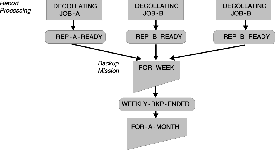
Backup Mission Workflow
The backup mission workflow of Control‑D is shown below. It illustrates the stages involved from initially scheduling the backup mission through backing up the CDAM datasets.
The following figure depicts the workflow of a backup mission:
Figure 56 Backup Mission Workflow
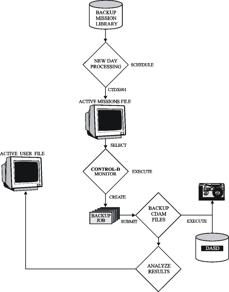
-
The Active User Report List file is scanned by the ControlD monitor for all reports requiring backup by the specified backup mission name. (This is a fast scan, not a scan of the entire file.) Reports that have been previously backed up, or have been restored from a backup, are not backed up a second time. The result of this process is a list of dataset names to be backed up.
-
The ControlD monitor reads a skeleton job from the library referenced by DD statement DADSKL of the ControlD monitor. The member name must be the same as the backup mission name (for example, BKP0031D).
Since the same library is used for printing, backup, restore and migration mission skeletons, the name of each mission must be unique.
When you define a new backup mission, you must create a new skeleton job with the same name.
The member must contain specific parameters that are interpreted by the ControlD monitor. The following table describes these parameters.
Table 162 Mandatory Parameters for Skeleton Member
Parameter
Description
%DSNS%
Resolves into a list of all the dataset names that have to be backed up. This list is in DF/DSS, DF/HSM, FDR, DMS/OS, ASM2 or ARCS format depending on installation parameters. Mandatory.
%TIMESTMP%
Resolves into a timestamp that is later used by Control‑D for internal purposes. Mandatory.
%MISSNAME%
Resolves into the backup mission name. Mandatory.
%COND% condnm
When the preparation of the backup job is completed, the specified condition name is added to the IOA Conditions file. The ODAT of the condition is the original scheduling date of the backup mission. This can be used for triggering the backup job under Control‑M. Optional.
%ODATE%
Resolves into Dyymmdd, where yymmdd represents the ODATE of the backup mission. Optional.
%TIME%
Resolves into Thhmmss, where hhmmss represents the start time of the backup mission. Optional.
%RETPD%
Resolves into nnnn, which represents the retention period of the produced backup data set according to the backup mission definition. Optional.
%EXPDT%
Resolves into the expiration date for the produced backup data set, in yyyy/ddd format, according to the backup mission definition. Optional.
-
When ControlD finishes preparing the member for submission, control passes to Exit CTDX010. This exit can modify the contents of the submitted job by adding, deleting or modifying the JCL. For example, the dataset names list can have a format different from the DF/DSS, DF/HSM, FDR, DMS/OS, ASM2 or ARCS format. The exit can return the following return codes:
Code
Description
0
Submit the job.
4
Do not submit the job (normally used when the submission is to be executed by a production control system).
Instead of using exit CTDX010, you can define parameter BKPJOBST=N in CTDPARM, which means “Do not submit the job.”
The member is written to the library referenced by DD statement DADJOB of the ControlD monitor with a name identical to the name of the backup mission. Therefore, this library must be different from the library referenced by DD statement DADSKL. The return code from the user exit determines if the job is or is not submitted. If ControlM is installed, submission of the job can be triggered by the %COND% statement. (The advantage of this method is that overall production tape workload and tape usage priority are taken into consideration when submitting the backup job.)
- The original member supplied contains the following:
- the DF/DSS, DF/HSM, FDR, DMS/OS, ASM2 or ARCS backup utility
- a program that analyzes the output of the backup process and updates ControlD files with the results (for example, the tape numbers used)
ControlD cannot use the ARCS, DFDSS, or FDR utility to back up CDAM data sets on more than five tape volumes unless the backup data sets are cataloged.
-
When the job finishes executing, the ControlD monitor is notified (by the second step) and the backup mission’s postprocessing parameters (OUT and SHOUT) are processed.
Exception Handling
If the backup job abends in the first step (BACKUP), the status of the backup mission is changed to ENDED‑NOTOK. When this happens, check why the abend occurred and correct the problem. After the problem has been corrected, rerun the backup mission from the Active Missions file.
If the backup job abends during the second step (ANALYZE), the status of the backup mission remains BACKUP IN PROCESS. When this happens, reset the backup mission status to ENDED through the BKPRESET job in the Control‑D JCL library. For more information on the BKPRESET utility, refer to the Control-D and Control-V utilities chapter of the INCONTROL for z/OS Utilities Guide.
If the backup mission ended NOTOK because one or more CDAM files were not backed up successfully, reorder the mission to back up only the CDAM files that were not backed up successfully during the previous run. Rerunning the same mission (without reordering it) reprocesses all CDAM files of the previous run including files that were successfully backed up.
Changing the Backup Mission Retention Period
The following table describes the parameters used by backup missions to specify the retention period of a backed up CDAM file:
Table 163 Parameters for Changing Backup Mission Retention Period
|
Parameter |
Description |
|---|---|
|
# OF DAYS TO KEEP |
Specifies how many days must elapse from the backup date to the expiration date. |
|
# OF GENERATIONS TO KEEP |
Specifies how many subsequent generations (executions) of the backup mission must be produced until the generation expires. |
You can specify either one (but not both) of these parameters in the backup mission definition screen. If you need to change from the # OF GENERATIONS TO KEEP method to the # OF DAYS TO KEEP method, use a new backup mission (that is, statement DO BACKUP in the decollation mission definition must refer to a new backup mission name). If the same backup mission is used, an error message is displayed and the backup mission ends NOTOK.
Backup Mission Considerations
The organization of backup missions is performed according to the backup cycles used at the site. A backup mission must be defined for each backup cycle.
Table 164 Backup Mission Cycle Example
|
Type |
Description |
|---|---|
|
BCK0007D |
Backup for one week |
|
BCK0014D |
Backup for two weeks |
|
BCK0031D |
Backup for one month |
|
BCK0091D |
Backup for three months |
|
BCK0365D |
Backup for one year |
Each backup mission archives on the same tape or cartridge all the reports assigned to it. The backup mission for archiving a report is selected in the job decollating parameters.
WHEN LINE 00001 - 00001 COL 00020 - 00080
    STRING ACCOUNTS RECEIVABLE - DAILY
   DO ..
   DO BACKUP=BCK0031D
WHEN LINE 00001 - 00001 COL 00020 - 00080
    STRING ACCOUNTS RECEIVABLE - BILLS
   DO ..
   DO BACKUP=BCK0007D
Different reports within the same job can be backed up for different retention periods.
The name of the backup mission is descriptive. The actual retention period is determined by parameter # OF DAYS/GENERATIONS TO KEEP in the backup mission. For example, backup mission BCK0031D can actually keep the reports on the tapes for 35 days.
Backup missions can be triggered based on the following:
-
time (for example, 04:00 a.m.)
-
automatic dependencies—when one or more specified jobs have been decollated
-
manual dependencies—the operator can decide when to start the backup process
-
a combination of the above
Restore Mission Management
This section discusses the following topics:
-
advanced scheduling issues
-
restoring according to scheduling dates
-
restore mission workflow
-
exception handling
-
restoring with the original backup utility
Advanced Scheduling Issues
Restoring According to Scheduling Dates
You can organize restore missions so that each day’s restore management (that is, the restore workflow) is the same. The simplest method is to specify DAYS=ALL in the Basic Scheduling parameters of all restore missions. Once a day, when the New Day procedure is invoked, all restore missions scheduled for the next 24 hours are placed on the Active Missions file.
This restore organization does not maximize the capabilities of Control‑D. You can organize the restore order in different ways for different days (for example, weekdays, weekends, end of the month, holidays).
Using Control‑D, you can define several copies of the same restore mission. Each copy is an independent definition of the restore mission and can have different scheduling criteria, different runtime criteria, and so on.
For example, the RSTNOON restore mission does not start later than 12:00 on every workday, does not start later than 11:00 at the end of the week, and is not scheduled for holidays.
Since there is no limit to the number of restore missions that can be defined, the user can organize the restore process to optimally suit every production day of the year.
Restore Mission Workflow
The following figure illustrates the restore mission workflow of Control‑D. It shows the stages involved from initially scheduling the restore mission through restoring the CDAM or Index datasets.
Figure 57 Restore Mission Workflow

The workflow of a restore mission is as follows:
-
Restore is requested by online users through option R of the History or Migrated Report List screen. The History or Migrated User Report List file is scanned by the ControlD monitor for all reports that need to be restored by the specified restore mission name. (This is a fast scan, not a scan of the entire file.) The result of this process is a list of dataset names to be restored.
-
The ControlD monitor reads a skeleton job from the library referenced by DD statement DADSKL of the ControlD monitor. The member name must be the same as the restore mission name (for example, RST0060M).
-
Since the same library is used for printing, migration, backup and restore mission skeletons, the names of the missions must be unique.
-
When you define a new restore mission, you must create a new skeleton job with the same name. The member must contain certain parameters that are interpreted by the ControlD monitor. The parameters are listed in the table below.
Table 165 Parameters for New Restore Mission Skeleton Job
Parameter
Description
%REPEAT% %ENDREPEAT%
Beginning and end of a repeating step. Mandatory. Since outputs can be backed up on many volumes, it is sometimes necessary (with certain archiving products) to perform the restore by more than one step. The definition of this repeating step is found between the %REPEAT% and %ENDREPEAT% statements (not applicable to DF/HSM, DMS/OS, ASM2 or ARCS formats).
%DSNS%
Resolves into a list of all the dataset names that have to be restored. This list is in DF/DSS, DF/HSM, FDR, DMS/OS, ASM2, or ARCS format, depending on installation parameters. Mandatory.
%VOLUMES%
Resolves into the volume serial numbers of the tapes taking part in the restore. (Applies to DF/DSS or FDR formats.) Mandatory when non-cataloged backup data sets are used. Not recommended when backup data sets are cataloged.
%TIMESTMP%
Resolves into a timestamp that is later used by Control‑D for internal purposes. Mandatory.
%MISSNAME%
Resolves into the restore mission name. Mandatory.
%COND% cond‑name
When the preparation of the restore job has been completed, the specified condition name is added to the IOA Conditions file. The ODAT of the condition is identical to the original scheduling date of the restore mission. This can be used for triggering the restore job under Control‑M. Optional.
%BKPUTIL%
Resolves to the backup utility name. Optional.
The value of this parameter is determined as follows:
-
The value of BKPUTIL in the skeleton is assigned as the utility name. For example, BKPUTIL=HSM.
-
If BKPUTIL is not set in the skeleton member, the Backup utility name is taken from the BKPUTIL installation parameter in the CTDPARM member of the IOA PARM library,
-
or
-
When restoring migrated reports, the Backup utility name is CTVMIG.
In all the sample skeleton members provided in the Control‑D SKL library, the appropriate backup utility name is already assigned to parameter BKPUTIL.
For details about how to use this parameter, see Restoring With the Original Backup Utility.
%MEDIANAME%
This parameter is used only in the skeleton restoring migrated reports. Resolves into the name of the media to which the reports are migrated. If reports to be restored have been migrated to different media, several Restore steps with different media names will be created in the job.
%ODATE%
Resolves into Dyymmdd, where yymmdd represents the ODATE of the backup mission that backed up the report. Optional.
%TIME%
Resolves into Thhmmss, where hhmmss represents the start time of the backup mission that backed up the report. Optional.
%DUMMY%
Intended for Control‑D internal use. Do not change.
%ANALYZE%
Intended for Control‑D internal use. Do not change.
-
-
When ControlD finishes preparing the member for submission, control is passed to User Exit CTDX011. This exit can modify the contents of the submitted job by adding, deleting or modifying the JCL. For example, the dataset names list can have a format different from the DF/DSS, DF/HSM, FDR, DMS/OS, ASM2 or ARCS format. The exit can return the following return codes:
Table 166 Return Codes for Exit CTDX011
Code
Description
0
Submit the job.
4
Do not submit the job (normally used when the submission is to be executed by a production control system).
Instead of using exit CTDX011, you can define parameter RSTJOBST=N in CTDPARM, which means “Do not submit the job.”
-
The member is written to the library referenced by DD statement DADJOB of the ControlD monitor, with a name identical to the name of the restore mission. Therefore, this library must be different from the library referenced by DD statement DADSKL. Depending on the return codes from the user exit, the job is, or is not, submitted. If ControlM is installed, submission of the job can be triggered by the %COND% statement. (The advantage is that overall production tape workload and tape usage priority are taken into consideration when submitting the restore job.)
The original member supplied is divided into
-
the DF/DSS, DF/HSM, FDR, DMS/OS, ASM2 or ARCS restore utility or CTVUMG utility by restoring migrated reports.
A step is created for each group of tapes (volsers) containing reports to be restored (not with all products). By restoring migrated reports, a step is created for each migration media.
-
a program that analyzes the output of the restore process and updates ControlD with the results
This step copies the restored user and report entries from the History or Migrated User Report List file to the Active User Report List file and indicates that a restore has been performed.
-
-
If a CDAM or Index file to be restored already exists on disk, that file is not restored to disk. If all the files to be restored already exist on disk, the restore mission creates a restore job that performs only the ANALYZE step. This step copies user and sysdata records from the History or Migrated User Report List file to the Active User file and ends OK.
-
When the job finishes executing, the ControlD monitor is notified (by the second step) and the restore mission’s postprocessing parameters (OUT and SHOUT) are processed.
Exception Handling
If the restore job abends in one of the first steps (such as the RESTORE step), rerun the job (enter the job in the Control‑D JCL library and submit it or, if scheduled under Control‑M, use the Control‑M rerun option without restart).
If the restore job abends in the last step (ANALYZE), rerun the job from the last step (that is, submit it again without restart).
If the last step abends, the status of the restore mission remains RESTORE IN PROCESS. To reset the restore mission status to ENDED, run the RSTRESET job from the Control‑D JCL library. This resets the restore mission. In addition, perform all the restore requests again (using option R in the History or Migration User Report List of Screen U). The restore mission finishes with ENDED NOTOK status.
For more information on the RSTRESET utility, refer to the Control-D and Control-V utilities chapter of the INCONTROL for z/OS Utilities Guide.
Restoring With the Original Backup Utility
Sites that are moving from one backup utility to another (for example, from FDR to DF/HSM) may end up having CDAM or Index files that are backed up by different backup utilities. Each of the backed up CDAM or Index files must be restored using the original backup utility.
To restore the CDAM or Index file with the appropriate backup utility, the restore mission name must point to a skeleton member of the original backup utility. Parameter BKPUTIL in the skeleton member must be set to the original backup utility name.
//* BKPUTIL=FDRCATThis statement must be in the skeleton member to use the FDR backup utility regardless of the value specified for BKPUTIL in member CTDPARM in the IOA PARM library.
The BKPUTIL value in the backup skeleton overrides the value of installation parameter BKPUTIL in member CTDPARM in the IOA PARM library.
Migration Mission Management (Control-V Only)
This section discusses the following topics:
Migrating Reports
Migration missions control the migration of Compressed Dataset Access Method (CDAM) reports and their indexes from one media (optical disk, cartridge, DASD, and so on) to another. They enable you to move data between fast access, higher cost media and slower access, lower cost media according to need. All user‑defined parameters are specified in the Migration Mission Definition screen.
For information about defining indexes and migration missions, see the chapter about decollating mission parameters in the Control‑D and Control‑V User Guide.
For information about CDAM files and migrated CDAM datasets, see the CDAM chapter in the Control‑D and Control‑V User Guide.
Multistage Migration
A maximum of 10 migration stages can be defined as a migration path in each migration mission. Single‑stage migration can be defined for reports whose remigration is not required.
Each migration stage specifies the target media, the age of the report in days when migration must occur, the cyclic time interval in days between refresh operations (when the report migrates to a new physical media of the same type), the prefix value (for migration to DASD and ROSs/OSS), and the FSET and VSET values (for migration to FileTek).
Migration Mission - Report Correspondence
The migration mission name is specified in the DO MIGRATE statement of a report’s decollation mission. A report retains its original migration mission name for its entire lifetime. Each migration mission defines all stages in the migration path for all reports whose decollation mission contains a DO MIGRATE statement specifying that migration mission’s name.
The user can modify the migration path and other parameters in a migration mission at any time. When a migration mission is modified, the migration of all reports whose decollation mission specifies that migration mission’s name are affected by the modification.
The retention period of each report is stored with the report. If the retention period of all reports previously migrated by a migration mission must be changed uniformly, modify parameter RETENTION DAYS in that migration mission and set parameter FORCE to Y (Yes). This causes $SYSDATA records created by previous runs of this migration mission to be updated with the new retention period during the next run of the modified migration mission. If parameter FORCE is not set to Y, only subsequently migrated reports receive the new retention period.
If the retention period of the previously migrated reports must be selectively changed, use utility CTDUPBKP.
Specify only one migration mission for each report. If more than one migration mission is specified in the decollation mission definition, a report’s files are migrated by that migration mission whose name is first encountered in the decollation process. Warning messages are generated if all CDAM files associated with a report do not have the same migration mission name.
If the decollation process detects more than one migration mission name, a warning is issued to the IOA Log file and the decollation process terminates with a status of ENDED OK – WITH WARNINGS. If $SYSDATA records created by different decollation missions for the same report contain more than one migration mission name, a warning is issued by utility CTDDELRP.
MIG and MSM Migration Types
Initial migration from DASD by the first stage (stage 01) in a migration path is called "MIG" migration. All subsequent migrations in the migration path are called "MSM" (multi-stage) migration. The migration type (MIG or MSM) is displayed in the TYP field of the Active Missions screen.
Scheduling Criteria
Separate scheduling criteria are specified for the two migration types.
-
MIG scheduling criteria are specified under STAGE 01 SCHEDULING PARAMETERS in the Migration Mission Definition screen. At most sites, stage 01 migration is scheduled frequently, perhaps daily, to remove reports from scarce DASD resources as soon as possible.
-
MSM scheduling criteria are specified under MIGRATION PATH SCHEDULING PARAMETERS in the Migration Mission Definition screen. At most sites, subsequent stages in the migration path are scheduled less frequently, perhaps every weekend, to minimize the extent to which running migration jobs impacts production jobs.
To minimize DASD utilization, schedule stage 01 (MIG type) migrations more frequently. To minimize the usage of computer resources when such resources are required for other jobs, schedule other (MSM type) migrations less frequently.
Primary and Secondary Migration
Each migration stage can contain a primary migration specification and, optionally, a secondary migration specification. Secondary migration produces a copy of primary migration reports (usually on less expensive media) that can be accessed if primary migration reports become damaged.
If SECONDARY MEDIA is specified in a migration mission, the migration mission submits the following migration jobs:
-
The primary migration job uses the migration skeleton. For more information, see Migration Mission Skeleton Jobs whose name is identical to the migration mission name.
-
The secondary migration job uses the migration skeleton whose name is specified in parameter SECONDARY SKELETON. This parameter defaults to the name of the primary migration mission, modified by changing the 3rd character to C (or to D if it had been C).
Only files designated as primary migration files can be accessed for viewing. If primary migration files are not usable for any reason, utility CTDUPBKP can be run to switch the primary and secondary migration designations. After running this utility, the secondary migration files are accessed for viewing. This utility can be run again to switch back to viewing primary migration files. The next Multi‑Stage Migration mission automatically recreates the primary migration files on the (originally) defined media.
Information about retention and about the current primary migration media can be displayed in $SYSDATA long format by using option A (Additional Info) in the Migrated Report list. Information about secondary migration media can be retrieved by running utility CTDUPBKP with parameter SIMULATE set to YES. For utility CTDUPBKP documentation, see the INCONTROL for z/OS Utilities Guide.
Secondary migration files are deleted when the next secondary migration is completed and at the end of the retention period. Refresh operations are performed independently for primary and secondary media.
Migration Mission Skeleton Jobs
Every primary and secondary migration mission must have its own skeleton job in a separate member of the Control‑D SKL library. The name of the member containing the skeleton job for a primary migration mission must be identical to the name of the migration mission. The name of the member containing the skeleton job for the secondary migration mission can be specified in parameter SECONDARY SKELETON in the migration mission.
In the Control‑D SKL library, member MIGLIM contains a skeleton job for a primary migration mission. Member MICLIM contains an almost identical skeleton job for a secondary migration mission. These skeleton jobs can be used "as is" (for migration missions MIGLIM and MICLIM) and can be duplicated (and modified) as required for other migration missions.
Because the same library is used for printing, backup, restore and migration mission skeletons, the names of all missions must be unique.
When defining a new migration mission, create a skeleton job member with the same name. To implement secondary migration, create a skeleton job member with the name in parameter SECONDARY SKELETON. The skeleton job format is identical for migration to all media types.
Skeleton jobs contain the parameters listed below. These parameters are interpreted (resolved) by the Control‑D and Control‑V monitor. All parameters (except %COND%) are mandatory and must remain exactly as written in the MIGLIM and MICLIM skeleton jobs.
Table 167 Parameters for Skeleton Jobs
|
Parameter |
Description |
|---|---|
|
%KODAK% / %ENDKODAK% |
Labels that enclose a part of the skeleton job that is placed in the migration job only when the target media is ROSs/OSS. |
|
%REPEAT% / %ENDREPEAT% |
Labels that enclose a part of the skeleton job that is repeated for every target media by Control‑D and Control‑V. |
|
%TARMEDIA% |
Name of the target media to which files are migrated. The value is specified in the migration mission definition. |
|
%MIGPREF% |
Prefix of the volume or platter to which files are migrated. If a value is not specified in the migration mission definition, NOCHECK is added to the job and the prefix is not checked. Optional. |
|
%LEVEL% |
For a migration mission with both primary and secondary migration, resolves to PRIMARY and SECONDARY in the appropriate jobs. For only primary migration, resolves to PRIMARY in step MIG and PRIMONLY in step ANALYZE. For only secondary migration, resolves to SECONDARY in step MIG and SECREFRESH in step ANALYZE. |
|
%MISSNAME% |
Migration mission name. |
|
%TIMESTMP% |
Timestamp that is later used by Control‑V for internal purposes. |
|
%VSET% / %FSET% |
VSET (volume set) and FSET (file set) parameters specified in the migration mission definition. These parameters are used only for migration to FileTek. For other target media, these parameters and DD statement FTKIN are not included in the migration job. |
|
%DSNS% |
List of datasets to be migrated by this mission. The Control‑D and Control‑V monitor obtains these values by scanning $SYSDATA records. |
|
%COND% condition |
Prerequisite condition to be added to the IOA Conditions file when preparation of the migration job is completed. The condition is specified in parameter OUT of the migration mission. The ODAT of the condition is identical to the original scheduling date of the migration mission. This mechanism can be used for triggering the migration job under Control‑M. Optional. |
Sample Skeleton Job
Skeleton job MIGLIM for primary migration is listed below. Skeleton job MICLIM for secondary migration is identical except the DSN suffix in DD statement SYSPRINT is S instead of P.
The labels %KODAK% and %ENDKODAK% enclose a part of the skeleton job that is placed in the migration job only when the target media is ROSs/OSS. (When the target media is not ROSs/OSS, nothing is inserted between these labels.)
//I900INMG JOB ,IOA900,MSGCLASS=X,CLASS=A,
// PERFORM=1
//*
%KODAK%
%ENDKODAK%
%REPEAT%
//MIGRAT  EXEC PGM=CTVMIG,PARM='%TARMEDIA%,%MIGPREF%,%LEVEL%'
//STEPLIB  DD DISP=SHR,DSN=IOAP.V900.LOAD
//DATRACE  DD DUMMY
//ERRLOG   DD SYSOUT=*,HOLD=YES
//DALOG    DD DISP=SHR,DSN=IOAP.V900.LOG
//DAMIG    DD DISP=SHR,
//     DSN=CTDP.V900.MIG.E000
//DAMIGI   DD DISP=SHR,
//     DSN=CTDP.V900.MIGI.E000
//SYSPRINT DD DSN=CTVP.V900.%MISSNAME%.MIGLIST.P,
//            DISP=(MOD,PASS,CATLG),SPACE=(CYL,(1,1)),UNIT=SYSALLDA
//SORTOUT  DD SYSOUT=*,HOLD=YES
//SORTWK01 DD UNIT=SYSALLDA,SPACE=(CYL,(20,40))
//SYSOUT   DD SYSOUT=*,HOLD=YES
//FTKIN    DD *
VSET=%VSET%
FSET=%FSET%
//SYSIN    DD *
%DSNS%
/*
%ENDREPEAT%
//*******************************************************************
//*               CONTROL‑D ANALYZE STEP                            *
//*               ----------------------                            *
//*******************************************************************
//ANALYZE EXEC PGM=CTDBKC,COND=EVEN,REGION=4096K,
//             PARM='%TIMESTMP%,%MISSNAME%'
//STEPLIB  DD DSN=IOAP.V900.TLOAD,DISP=SHR
//         DD DSN=IOAP.V900.LOAD,DISP=SHR
//TAPE     DD DUMMY
//SYSIN    DD DSN=CTVP.V900.%MISSNAME%.MIGLIST.P,
//          DISP=(OLD,DELETE,CATLG)
//DAAMF    DD DISP=SHR,
//     DSN=CTDP.V900.AMF
//DAAMF1   DD DISP=SHR,
//     DSN=CTDP.V900.AMF
//DALOG    DD DISP=SHR,
//     DSN=IOAP.V900.LOG
//DAACT    DD DISP=SHR,
//     DSN=CTDP.V900.ACT.E000
//DAACTI   DD DISP=SHR,
//     DSN=CTDP.V900.ACTI.E000
//DAMIG    DD DISP=SHR,
//     DSN=CTDP.V900.MIG.E000
//DAMIGI   DD DISP=SHR,
//     DSN=CTDP.V900.MIGI.E000
//SYSPRINT DD SYSOUT=*,HOLD=YES
//SYSABEND DD SYSOUT=*,HOLD=YES
//DATRACE  DD SYSOUT=*,HOLD=YES
//
Target Media Types
The following table describes the supported migration target media types:
Table 168 Migration Target Media Types
|
Type |
Description |
|---|---|
|
UFS |
UNIX File System (UFS) for migration to a Network File System (NFS) |
|
CART |
3490/3490E/3590 Tape Cartridge |
|
OSS |
DataWare/ROSs/OSS or compatible |
|
DASD |
|
|
FTK |
FileTek Storage Machine (SM) |
|
OAM |
IBM Object Access Method |
|
CENTERA |
EMC Centera Storage System |
Each site can use any or all of the supported types of migration target media. Media‑specific parameters (NAME, TYPE, DSNPREF, UNITNAME, DEVADDR, and so on) must be defined in the IOASPRM member in the IOA PARM for each target media type (including DASD) that is used.
For details about these parameters, see the Control‑V chapter in the INCONTROL for z/OS Installation Guide: Installing.
For more information about the supported media types, see Device Definition and Usage.
Migration to Unix File System (UFS)
To use a UNIX File System (UFS) media type, the UNIX System Services (USS) must be configured and enabled, and the Language Environment runtime libraries must be in the LINKLIST on the LPAR where Control-V runs.
Migration to UFS is useful when you want to use the NFS protocol to migrate Control-D reports to a remote filesystem mounted on a local UNIX directory (also known as a mount point). Therefore, the z/OS NFS client must be configured and active on the LPAR where Control-V runs.
From the Control-V perspective, the files migrate to a USS file system. The use of NFS is completely transparent to Control-V, since all NFS-related functionality is provided by underlying layers of the operating system. Therefore, you must define the remote filesystem and mount it with the NFS protocol to a local USS mount-point directory.
To set up for migration to UFS, you create a primary target migration directory and a secondary migration directory. You then specify these directories in Control-V using the PATHPRI and PATHSEC parameters, respectively. In both these directories, you store a file that is designed to prevent migration of reports to the local mount point directory when the remote NFS is not mounted. Specify this file in Control-V using the POOL parameter.
During file migration, the full absolute name of the migrated file is stored in the SYSDATA record. All extents of one CDAM data set are always stored into a single migrated file on UFS.
To specify permissions for the migrated files, use the FILEPERM parameter. In addition, ensure that all Control-V components that interact with UFS media run under a USER and GROUP that have full access permissions (create/write/read/delete) to the target migration folders. Also, remember that the user's UMASK value can impact file permissions for the migrated files.
To ensure high performance, set the maximum number of UFS devices that IOASMON can create, using the MAXCONN parameter.
The following table summarizes the parameters that you must specify when the target media is UFS:
Table 168a Mandatory Parameters for UFS Media
|
Parameter |
Description |
|---|---|
|
PATHPRI |
Primary target migration directory that you prepared for UFS migration, specified as an absolute path. The path is case-sensitive and it must end with a slash. The maximum allowed length is 13 characters. You can also use UNIX symbolic links. |
|
PATHSEC |
Secondary target migration directory that you prepared for UFS migration, specified as an absolute path. The path is case-sensitive and it must end with a slash. The maximum allowed length is 13 characters. You can also use UNIX symbolic links. |
|
POOL |
Name of a file that you prepared and stored in both the primary and secondary target migration directories on the NFS server. Case-sensitive. This file prevents Control-V from migrating reports to the local mount point directory when the remote NFS is not mounted. |
|
FILEPERM |
File permissions for the migrated files, in octal notation |
|
MAXCONN |
Maximum number of UFS devices that the IOA Archive Server Monitor (IOASMON) can create. |
Migration to Cartridge (CART)
When migrating to media type CART, the migration mission places as many files as possible on the same volume. Any space remaining is used by a subsequent run of the same migration mission. When insufficient space remains, a scratch volume is used.
Before writing each file, the migration process determines if the file fits on the volume (based on the CART media capacity parameter CARTLEN specified in the IOASPRM member). If the file does not fit, a new scratch volume is used. If the file is larger than the specified volume capacity, the migration process uses a new volume for that file and then uses as many volumes (not exceeding five) as needed.
Miscalculating the remaining space (because the specific volume was smaller or the compression factor was lower than expected) can cause the file to span more than one volume. This can result in slower retrieval response time.
Migration Without Cataloging
By default, all migrated CDAM and Index files are cataloged, however, you can migrate these files to cartridge without cataloging them. When you use this option, the DEVICE_TYPE and VOLSER file parameters, as well as the file sequence number, are kept in the Control-D database instead of in the System catalog. This option is available for files that are migrated to one or two volumes only.
To activate this option, specify N in the CTLG field of the media line in the Migration Mission Definition screen. Large files migrated to more than two volumes will be cataloged even if this option is activated.
Using this option requires that
-
when running the CTVCLMIG utility, the value of the TAPELIST parameter is set to YES to produce the list of expired cartridges for the Tape Management System.
-
once this option has been used, you can only use Control-V multistage migration to move the migrated files from one volume to another. You must not move the migrated files from one volume to another outside of ControlV.
Migration to ROSs/OSS
The EXEC statement in the OSS migration skeleton’s SRVD step contains PARM='OSS'. Change OSS to the logical name of the target media specified in the IOASPRM member in the PARM library.
It is recommended that you specify a set of platters to which reports (and indexes) must migrate. Use meaningful prefixes to create sets of platters containing reports with similar characteristics (for example, viewed together, viewed with similar frequencies, viewed by the same group of users). If you do not specify a prefix in the migration mission, the report migrates to the first available platter.
The user defines ROSs/OSS platters and the VOLSERs on each platter. The platter prefix in a migration mission resolves to the value specified in parameter PREFIX of the Migration Mission Definition screen. This platter prefix enables the migration process to select the desired platter.
After selecting a platter, the migration process scans the VOLSER list and selects the first completely empty VOLSER in the list. CDAM files migrate sequentially until this VOLSER is filled (to a maximum of 32K blocks on any volume). "Virtual" VOLSERs that are not filled in one migration mission are left partially empty, but no physical platter space is wasted.
When a file is written on a VOLSER on the ROSs/OSS, it is cataloged on that VOLSER with the specific label number. The VOLSER of each migrated report is stored both on the catalog and in the Control‑V Migrated User Report file. When the report is viewed, this catalog entry enables the ROSs/OSS to access the needed platter and read the required VOLSER. When all VOLSERs on a specific platter are no longer needed, the user can destroy the platter.
Migration to Disk or BMC AMI Cloud, Fat-DASD, and IBM 3995 Optical Library Dataserver (in 3390 Emulation Mode)
It is recommended that you specify the prefix of a set of VOLSERs to which the reports must migrate. Use meaningful prefixes to create sets of volumes containing reports with similar characteristics (for example, viewed together, viewed with similar frequencies, viewed by the same group of users). If you do not specify a prefix in the migration mission, the report migrates to the first available VOLSER that belongs to the mainframe UNIT specified in the media definition.
Migration to BMC AMI Cloud media is the same as migration to Disk. The migrations are directed by SMS to a specific DASD storage group. BMC AMI Cloud then archives the CTD/V reports to the cloud by using a dedicated BMC AMI Cloud archive policy. When CTD/V requires a report, BMC AMI Cloud recalls it seamlessly. For more information, see Creating a data set archive policy in the BMC AMI Cloud Data and BMC AMI Cloud Vault online documentation.
Migration to FileTek Storage Machine
The following table describes the parameters that must be specified when the target media is a FileTek Storage Machine:
Table 169 Mandatory Parameters for FileTek Storage Machine Target Media
|
Parameter |
Description |
|---|---|
|
VSET |
Volume set of the storage machine to be used for the migration mission. |
|
FSET |
File set of the storage machine to be used for the migration mission. |
If you do not specify these parameters, the default VSET and FSET for the FileTek user ID specified in the IOASPRM member in the PARM library is used.
For information on determining the Volume set and File set, see the FileTek Storage Machine documentation.
If separate VSET and FSET values need to be specified for different groups of users, define a separate migration mission for each group.
Migration to OAM
During the migration process, the Control‑V migration program interfaces with the IBM OAM through the OSREQ application interface to store the report as OBJECTs in a COLLECTION. The size of the OBJECTs are determined by media specific parameters defined in the IOASPRM member.
Migration to OAM enables you to migrate many CDAM and Index files into a single OAM collection. This reduces the number of entries in the system catalog and improves system performance.
The SMS management system, guided by the user’s definition in an ACS routine, directs the data server to transport the collection of OAM objects to a 3995 device. The user cannot specify parameters to SMS through Control‑V. Therefore, all parameters for SMS must be specified externally.
Figure 59 Migration to OAM

Migration to Centera
The EMC Centera storage system is used for report migration. During the migration process, each CDAM file is put into separate Centera clips as a BLOB and the clip-id is stored in SYSDATA records for later access. Centera node addresses are taken from the POOL1 through POOL4 parameters of the corresponding media, as defined in IOASPRM.
Because the Centera SDK works over TCP/IP, all address spaces using the SDK (migration jobs, IOASMON, CTVCLMIG utilities, and CTVUNMIG) should run under an RACF user with defined OMVS segment.
You must be running z/OS 1.2 or higher when using Centera SDK in the migration process.
In order to use Centera authorization based on the PEA profiles, perform the following steps:
-
Allocate a file with attributes RECFM=VB, LRECL=1024, BLKSIZE=4096 and insert the Centera PEA text in ASCII. The text should be transferred to the mainframe in binary format. For example, the file DS name is CTD.CENTPEA.
-
Create the CENTCONF member in the IOA PARM library with the following content:
CopyCENTERA_PEA_LOCATION=//'CTD.CENTPEA'X’00’ must be specified after the last apostrophe.
-
Add the following DD card to the migration skeleton and to the IOASMON, CTVCLMIG, and CTVUNMIG procedures:
Copy//FPCONFIG DD DISP=SHR,DSN=&ILPREFA..PARM(CENTCONF)
If Centera authorization fails, the job or STC receives an error code of -10153. For example:
IOA5E4E CENTERA INIT ERROR: RC=0008, REASON CODE=-10153
Naming Conventions
CDAM Datasets
A primary migrated CDAM dataset conforms to the following naming convention:
pmigpref.jobname.jobid.datetime.fileidwhere pmigpref is the file name prefix. Based on the length of the DSNPREF parameter in the IOASPRM member in the IOA.PARM library, which should be the same as the length of the IXHPREF parameter in the CTVPARM member, the file name prefix structure can be built in one of the following ways:
-
If DSNPREF is three characters long, pmigpref is built as DSNPREF.PREFIX, where PREFIX is the original CDAM prefix.
-
If DSNPREF is one or two characters long, pmigpref is built by inserting the first DSNPREF character into the original index file prefix.
-
If DSNPREF is one character, it is inserted into the first position.
If DSNPREF=M and the original CDAM file prefix is CTDP.L2, pmigpref is MCTDP.L2.
-
If DSNPREF is two characters long, the second character is an integer from 1 to 7, representing the number of the position into which the first DSNPREF character is inserted.
If DSNPREF=M6 and the original CDAM file prefix is CTDP.L2, pmigpref is CTDP.ML2.
A secondary migrated CDAM dataset conforms to the following naming convention:
smigpref.jobname.jobid.datetime.fileidwhere smigpref is the file name prefix. Based on the length of the SECPREF parameter in the IOASPRM member in the IOA.PARM library, which should be the same as the length of the IXHPREF parameter in the CTVPARM member, the file name prefix structure can be built in one of the following ways:
-
If SECPREF is three characters long, smigpref is built as SECPREF.PREFIX, where PREFIX is the original CDAM prefix.
-
If SECPREF is one or two characters long, smigpref is built by inserting the first SECPREF character into the original index file prefix, using the same method as pmigpref is built from DSNPREF.
-
For example, if SECPREF=S and the original CDAM file prefix is CTDP.L2, smigpref is SCTDP.L2. If SECPREF=S6 and the original index file prefix is CTDP.L2, smigxpref is CTDP.SL2.
The other qualifiers are copied from the original CDAM dataset name. For more information, see the CDAM chapter in the Control-D and Control-V User Guide.
For both primary and secondary migration, the datetime field has the following format:
datetimeThis field is a Control-V generated timestamp. When a CDAM dataset migrates from disk to the level 01 target media, this field remains prefixed by the letter D. This letter is replaced by the next letter in alphabetical sequence during each stage of the multistage migration or refresh.
Indexes
An index file conforms to the following naming convention:
indpref.jobname.date.time.fileidwhere indpref is the index file prefix.
Based on the length of the IXHPREF parameter in the CTVPARM member in the IOA.PARM library, the index file name prefix structure can be built in one of the following ways:
-
If IXHPREF is three characters long, indpref has following structure:
Copyixhpref.ixprefwhere
ixhpref is the 3-character first level qualifier prefix specified in the IXHPREF parameter. All indexes have the same IXHPREF value.
ixpref is the second level prefix specified in the IXPREF parameter in the CTVPARM member of the IOA.PARM library. All indexes have the same IXPREF value.
-
If IXHPREF is one or two characters long, indpref takes the value of the CDAM file prefix with one of the characters replaced to the value specified in first character of IXHPREF. Parameter IXPREF from CTVPARM is not used in this case.
-
If IXHPREF is one character, the first character of the CDAM prefix is replaced.
If IXHPREF=I and the CDAM file prefix is CTDP.L2, indpref is ITDP.L2.
-
-
If IXHPREF is two characters, the second character is a digit from 1 to 7 and it means the position number of the character which is replaced.
If IXHPREF=I6 and the CDAM file prefix is CTDP.L2, indpref is CTDP.L2.
date is the letter C followed by the 5-character date in the julian format, YYDDD.
time is the letter T followed by 6 characters indicating the time in hhmmss format.
fileid is the file ID beginning with the letter M, followed by one digit (from 1 to 9) that indicates the number of the monitor that created the index, followed by the 3-digit sequential number of the index produced in the decollation mission.
A primary migrated index conforms to the following naming convention:
pmigxpref.jobname.date.time.fileidwhere pmigxpref is the file name prefix. Based on the length of the DSNPREF parameter in the IOASPRM member in the IOA.PARM library, which should be the same as the length of the IXHPREF parameter in the CTVPARM member.
The index file name prefix structure can be built in one of the following ways:
-
If DSNPREF is three characters long, pmigxpref is built as DSNPREF.IXPREF, where IXPREF is the second level prefix specified in the IXPREF parameter in the CTVPARM member.
-
If DSNPREF is one or two characters long, pmigxpref is built by inserting the first DSNPREF character into the original Index file prefix.
-
If DSNPREF is one character, it is inserted into the first position.
For example, if DSNPREF=M and the original Index file prefix is ITDP.L2, pmigxpref is MITDP.L2.
-
If DSNPREF is two characters, the second character is a digit from 1 to 7 and it means the number of position into which the first DSNPREF character is inserted.
For example if DSNPREF=M6 and the original Index file prefix is CTDP.I2, pmigxpref is CTDP.MI2.
-
A secondary migrated index conforms to the following naming convention:
smigxpref.jobname.date.time.fileidwhere smigxpref is the file name prefix. Based on the length of the SECPREF parameter in the IOASPRM member in the IOA.PARM library, which should be the same as the length of the IXHPREF parameter in the CTVPARM member, the file name prefix structure can be built in one of the following ways:
-
If SECPREF is three characters long, smigxpref is built as SECPREF.IXPREF, where IXPREF is the second level prefix specified in the IXPREF parameter in the CTVPARM member.
-
If SECPREF is one or two characters long, smigxpref is built by inserting the first SECPREF character into the original Index file prefix by the same way as pmigxpref is built from DSNPREF.
For example, if SECPREF=S and the original Index file prefix is ITDP.L2, smigxpref is SITDP.L2; if SECPREF =S6 and the original Index file prefix is CTDP.I2, smigxpref is CTDP.SI2
For both primary and secondary migration, the date field has the following format:
date
When an index migrates from disk to the level 01 target media, this field remains prefixed by the letter C. This letter is replaced by the next letter in alphabetical sequence during each stage of the multistage migration or refresh.
The other qualifiers are copied from the original index name.
OAM Collections and Objects
The naming structure of OAM Collections and Objects depends on the status of optional Wish WV0390.
-
If optional Wish WV0390 is not applied
-
each CDAM or Index file is migrated into a separate OAM collection.
-
collection names are built the same way as the migrated CDAM or Index file names, as described in CDAM Datasets and Indexes.
-
object names conform to following naming convention:
CopyCTV.Nx.Nxxxxxxxwhere CTV, N, and N are constants, and xxxxxxxx is the serial number of the object inside the collection.
-
-
If optional Wish WV0390 is applied
-
many CDAM and Index files are migrated into the same OAM collection.
-
the collection name conforms to following naming convention:
Copycolpref.migmis.Nxxxxxxxwhere
-
colpref is the collection name prefix. Based on the length of the DSNPREF parameter (for primary migration) or the SECPREF parameter (for secondary migration) in the IOASPRM member in the IOA.PARM library, the collection name prefix structure can be built in one of the following ways:
-
If the parameter is three characters long, colpref is DSNPREF for primary migration or SECPREF for secondary migration.
-
If DSNPREF (or SECPREF for secondary migration) is one or two characters long, colpref is built by concatenating the DSNPREF (or SECPREF for secondary migration) character with the constant CTVOAM.
-
-
migmis is name of the migration mission that migrates files to this collection.
-
Nxxxxxxx is the serial number of the collection inside of the migmis migration mission.
-
-
-
The object name conforms to following naming convention:
Copymigfname.Nxxxxwhere
-
migfname is built as follows:
-
For migrated CDAM files migfname is built from the original CDAM file name by excluding the fifth qualifier, STEP#, from the name.
-
For migrated index files, if IXHPREF is three characters long, migfname is built from the original index file name by excluding the first qualifier, IXHPREF, from the name.
-
For migrated index files, if IXHPREF is one or two characters long, migfname is equal to the original index file name.
-
-
Nxxxx is the letter N followed by the serial number of the object inside the migrated file.
-
Migration Mission Workflow
A migration mission consists of the following steps:
-
Ordering one migration mission adds a MIG mission to the Active Missions file (if its scheduling criteria are satisfied) and adds a MSM mission to the Active Missions file (if its scheduling criteria are satisfied). TheMIG mission migrates reports from DASD to the stage 01 target media. TheMSM mission migrates reports from the media on which they currently reside (stage n1) to the target media of stage n.
-
If MIG and MSM missions with the same name exist concurrently, the status of both missions is "IN PROCESS" but the ControlD and ControlV monitor ensures that job MSM is not created and submitted before job MIG ends.
-
The MIG mission scans $SYSDATA records in the Active User file and the MSM mission scans $SYSDATA records in the Migrated User file to find records for all reports that need to be migrated by the migration mission. This process produces a list of datasets to migrate.
-
The ControlD and ControlV monitor looks for the primary migration skeleton job in the library referenced by DD statement DADSKL of the ControlD and ControlV monitor. Themember name must be the same as the primary migration mission name (for example,MIG0007Y).
-
If secondary media values are specified in a migration mission stage, the ControlD and ControlV monitor looks for the secondary migration skeleton job in the library referenced by DD statement DADSKL of the ControlD and ControlV monitor. Themember name must be the same as the secondary migration mission name specified in parameter SECONDARY NAME in the Migration Mission Definition screen.
-
Primary and secondary migration skeletons are tailored to produce jobs that perform the appropriate migrations and analyze the results. For MSM, the MIGRAT step is automatically duplicated for each migration stage that must be included in the migration job.
-
The age of each report is calculated by subtracting the ODATE of its decollation mission from the ODATE of the migration mission that controls its migration. This calculation method permits testing whether a report will migrate on a future date, by specifying that date in the migration mission’s ODATE parameter. (An installation parameter enables calculating the age of each report by subtracting the ODATE of its decollation mission from the current installation date. This calculation method does not permit such testing.)
-
If a report does not currently reside on the media specified for its age (as calculated in the previous step), it is migrated to the specified media by the migration mission. Ifa report migrated by a migration stage has resided on a media for the number of days specified in parameter REFRESH EVERY for that stage, the media is refreshed by the migration mission.
-
When the migration job is ready for submission, control is passed to User Exit CTDX010. This exit can add, delete or modify JCL statements in the job. Exit CTDX010 returns one of the following return codes:
-
0 – submit the job
-
4 – do not submit the job
This return code is normally used when the job must be submitted by ControlM or another production control system.
Instead of using exit CTDX010, you can define parameter BKPJOBST=N in CTDPARM, which means “Do not submit the job.”
-
-
The migration job JCL is written to the library referenced by DD statement DADJOB of the ControlD and ControlV monitor with a name identical to the name of the migration mission. Therefore, this library must not be the skeleton library referenced by DD statement DADSKL.
-
If %COND% is specified in the migration skeleton, the resolved condition is added to the IOA Conditions file. Depending on the return code from User Exit CTDX010, the job is or is not submitted. IfControlM is installed, submission of the job can be triggered by the condition added by a %COND% statement.
-
If the migration target media is OSS (DataWare/ROSs/OSS or compatible), the migration job begins with step SRVD, which releases an OSS device, and step OSSDBEXT, which creates the OSS Extract Dataset using information from the OSS Database.
-
The migration process creates and/or updates $SYSDATA records in the Migrated User file with target media, target prefix, timestamp, and other migration parameters for both primary and secondary migration. All $SYSDATA records pointing to a migrated report are updated with the new migration information.
-
For migration stages whose target media is CART, ControlV records the VOLSER of the last used tape. This enables the next invocation of that migration mission to use the same tape.
-
The original copy of each report that expires or moves to another physical media is marked for deletion. Actual deletion is performed during the next run of utility CTVCLMIG. This utility must be run periodically.
-
When the job finishes executing, the ControlD and ControlV monitor is notified by the ANALYZE step and the migration mission’s postprocessing parameters (OUT and SHOUT) are processed.
Example: Multi-stage Migration Mission Workflow
The cumulative retention period for reports in this example is 8 years.
Table 170 Multi-stage Migration Mission Workflow Example
|
Stage |
Decollating Mission |
|
|---|---|---|
|
Report Processing |
Every workday, CDAM reports and indexes are stored on DASD for 1 month. |
|
|
Primary Migration |
Secondary Migration |
|
|
Stage 01 Migration |
Every weekend, 5 reports Optical media is refreshed every 6 months. |
Every weekend, 5 reports CART media is refreshed |
|
Stage 02 Migration |
Every month, reports and CART media is refreshed |
|
The following figure illustrates an Optical media that is refreshed after six months and a CART media that is refreshed after 4 years. This multi-stage migration mission is specified in the migration mission definition.
Figure 60 Multi-stage Migration Mission Workflow

Figure 61 Migration Mission Definition
  ---- Control‑V CATEGORY MIGOS1C7          MIG MISSION MIGOS1C7 --------(M.S)
    COMMAND ===>                                                 SCROLL===> CRSR
  +‑‑‑‑‑‑‑‑‑‑‑‑‑‑‑‑‑‑‑‑‑‑‑‑‑‑‑‑‑‑‑‑‑‑‑‑‑‑+
  ======= >>>>>>>>>>>>>>>> TOP OF CATEGORY PARAMETERS <<<<<<<<<<<<<<<<<< =====
    CATEGORY MIGOS1C7                          MISSION MIGOS1C7
    OWNER    M15           TASKTYPE MSM        GROUP
    DESC
    ===========================================================================
                          STAGE 01 SCHEDULING PARAMETERS
    DAYS                                                          DCAL
                                                                       AND/OR
    WDAYS                                                         WCAL
    MONTHS  1‑ Y 2‑ Y 3‑ Y 4‑ Y 5‑ Y 6‑ Y 7‑ Y 8‑ Y 9‑ Y 10‑ Y 11‑ Y 12‑ Y
    DATES
    CONFCAL          SHIFT   RETRO N MAXWAIT 00
    MINIMUM          PDS
    ===========================================================================
    IN        MIG-DASD-TO-OSS-11M ODAT
    TIME FROM      TO      NOT LATER THAN      PRIORITY
    ===========================================================================
    OUT
    SHOUT WHEN NOTOK                               TO OPER             URGN R
     MSG MIGOS1C7 STAGE 01 ENDED NOT OK
    SHOUT WHEN                                     TO                  URGN
     MSG
    ===========================================================================
    RETENTION DAYS 02922         FORCE          SECONDARY SKELETON  MICOS1C7
    ===========================================================================
    STAGE 01 PRIMARY   MEDIA NAME OSS      AGE 00030 REFRESH EVERY 00183
             PREFIX
             SECONDARY MEDIA NAME CART              REFRESH EVERY 01460
    ===========================================================================
                        MIGRATION PATH SCHEDULING PARAMETERS
    DAYS                                                          DCAL
                                                                       AND/OR
    WDAYS   0,6                                                   WCAL
    MONTHS  1‑ Y 2‑ Y 3‑ Y 4‑ Y 5‑ Y 6‑ Y 7‑ Y 8‑ Y 9‑ Y 10‑ Y 11‑ Y 12‑ Y
    DATES
    CONFCAL          SHIFT   RETRO N MAXWAIT 00
    MINIMUM          PDS
    ===========================================================================
    IN        MIG-OSS-TO-CART-7Y ODAT
    TIME FROM      TO      NOT LATER THAN      PRIORITY
    ===========================================================================
    OUT
    SHOUT WHEN NOTOK                           TO OPER              URGN R
     MSG MIGOS1C7 STAGE 02 ENDED NOT OK
    ===========================================================================
    STAGE 02 PRIMARY   MEDIA NAME CART    AGE 00365 REFRESH EVERY 01460
             SECONDARY MEDIA NAME                   REFRESH EVERY
    STAGE 03 PRIMARY   MEDIA NAME          AGE      REFRESH EVERY
             SECONDARY MEDIA NAME                   REFRESH EVERY
    ===========================================================================
======== >>>>>>> END OF MIGRATE MISSION PARAMETERS OF THIS CATEGORY <<<<<< =====

 PLEASE FILL IN MISSION PARAMETERS. USE "SHPF" TO SEE PFK DEFINITION    11.04.10
Exception Handling
If the migration job abends in the first step (MIGRAT), the status of the migration mission is changed to ENDED-NOTOK. When this happens, check why the abend occurred and correct the problem. After the problem has been corrected, rerun the migration mission from the Active Missions file.
If the migration job abends during the second step (ANALYZE), the status of the migration mission remains MIGRATION IN PROCESS. When this happens, reset the migration mission status to ENDED through the MIGRESET job in the Control-D JCL library. For more information on the MIGRESET utility, refer to the Control-D and Control-V utilities chapter of the INCONTROL for z/OS Utilities Guide.
If a migration mission ends NOTOK because one or more CDAM files did not migrate successfully, the same mission can be rerun by specifying option R in the Active Missions Environment screen, or it can be reordered. In either case, only CDAM files that did not migrate successfully during the previous run are migrated.
Submitting a partially run migration job does not create duplicate copies of files on the target media. The migration job verifies that each file is cataloged, with the appropriate migration prefix.
Global Index Facility (Control-V Only)
The Global Index facility is a Control‑V feature that allows the end-user to select reports for viewing based on the index values found in the Global Index database.
Control‑V maintains a separate index for every report in the Control‑V repository. By selecting reports by a particular index value, the user selects a set of reports, and Control‑V searches all indexes of those reports for the indexes that contain the particular index value.
The Global Index facility maintains the Global Index database. This database contains multilevel index values that point to a list of reports that contain these index values.
Using the Global Index database, you can get a list of multilevel index values and quickly create a Report list using the Hit-list method when you specify index names and values in the selection criteria. Using the Global Index database with the Hit-list method eliminates searching every index file.
For more information on how reports are accessed through the Global Index database, see Accessing Reports Through the Global Index Database
Creating and Maintaining the Global Index Database
The Global Index Database is implemented as a set of DB2 tables.
The following steps should be performed to install the Global Index Database:
-
Define which Control-V index paths you would like to load into the Global Index Database.
-
Create DB2 tables for storing these paths, and create DB2 indexes. For details see Creating DB2 Tables.
-
Prepare the CTDGIDB2 special member to describe the relationship between the ControlV index paths and DB2 tables. For details see Relationship Between CTV Index Paths and DB2 Tables.
-
Bind the DB2 application plan for the CTDGID Global Index interface module. For details see Global Index Interface.
-
Prepare jobs for loading information into the DB2 tables. For details see Loading Information into the Global Index DB2 Tables.
-
Prepare jobs for cleaning up the DB2 tables. For details see Cleaning the Global Index Database.
Creating DB2 Tables
All Global Index values associated with a particular Global Index path are stored in a DB2 table. Fields in the table correspond to the fields of Control‑V indexes. An additional field REP_KEY contains the key of the corresponding Control-D report entry. The REP_KEY field should be defined with the FOR BIT DATA clause.
Several Control‑V Index paths can be stored into the same DB2 table if the table contains fields from all the paths. Such a table can be used in the event that there is a Control‑V path that covers all the fields in the table. For example, if there are three Control-V Index paths
-
ACCOUNT
-
ACCOUNT/DATE
-
ACCOUNT/NAME
you can organize two DB2 tables. One table would contain the ACCOUNT and the ACCOUNT/DATE paths, while the other would contain only the ACCOUNT/NAME path.
If there is a large number of entries to be loaded into the DB2 table, several tables can be created to keep entries for the same Control-V Index path. You can create a new DB2 table, depending on your needs, for each year, quarter, month, multiple years and so on. To identify each table you can use a suffix to the table name to identify the period covered by the table. For example, if you created a new table for each year the names would be CTD.GIRD07 to keep data of year 2007, CTD.GIRD08 to keep data of year 2008, and so on. These tables are joined during data retrieval or you can specify a specific table to process. For more information, see Accessing Reports Through the Global Index Database.
Additional DB2 tables containing only high level Indexes of the Index Path can be created to improve the performance of the Index values list request. For example, if the main DB2 table contains the values of the Index path DEPARTMENT/TEAM/ACCOUNT, and there is not an especially large number of DEPARTMENT values and TEAM values, getting a list of Departments or Teams from a large DB2 table can take a disproportionately long time. In this case, it makes sense to create two additional DB2 tables: CTD.DEP with the DEPARTMENT values only and CTD.DEP_TEAM with two columns - DEPARTMENT and TEAM. The result is, the retrieval of the DEPARTMENT list is done from the CTD.DEP table and retrieval of the TEAM list for each DEPARTMENT from the CTD.DEP_TEAM table instead of performing these requests from the big main table. The additional tables can be handled manually or can be loaded automatically while loading the main table. This is done using the CTVUPGDB utility or from within a decollation mission. Use of such additional tables is optional, it can be specified in the CTDGIDB2 member (For more information, see Relationship Between CTV Index Paths and DB2 Tables.
The database administrator at the site is responsible for the design and organization of the DB2 tables. The database administrator should make needed definitions according to the requirements of the application to be implemented and according to the amount of information which is to be stored in the Global Index Database.
A DB2 index should be created for each DB2 table in order to prevent adding duplicate index values into the table, and in order to provide better performance when retrieving index values. The CTDGBCRT member in the CTD JCL library is a sample job for creating the DB2 table. An example of this job is shown in the following figure.
Figure 62 CTDGBCRT Member Sample Job
//DSNTEP2 EXEC PGM=IKJEFT01,DYNAMNBR=20
//DBRMLIB   DD  DSN=DSN610.DBRMLIB.DATA,DISP=SHR
//SYSTSPRT  DD  SYSOUT=*
//SYSPRINT  DD  SYSOUT=*
//SYSUDUMP  DD  SYSOUT=*
//SYSIN     DD  *

  CREATE TABLE CTD.GIRAD
   (ACCOUNT CHAR(10) NOT NULL,
    DATE_   CHAR(8)  NOT NULL,
    REP_KEY CHAR(24) NOT NULL FOR BIT DATA)
   IN DBCTD.TSCTD;

  CREATE TYPE 2 UNIQUE INDEX CTD.IXGIRAD ON CTD.GIRAD
   (ACCOUNT ASC,
    DATE_   ASC,
    REP_KEY ASC)
    CLUSTER
    CLOSE YES

    USING STOGROUP SGCTD
    PRIQTY 1000000
    SECQTY 100000
    ERASE NO

    FREEPAGE 10
    PCTFREE 20;

  GRANT SELECT ON TABLE CTD.GIRAD TO PUBLIC
//SYSTSIN DD *
  DSN SYSTEM(DSN1)
  RUN  PROGRAM(DSNTEP2) PLAN(DSNTEP61) -
       LIB('DSN610.RUNLIB.LOAD')
 END
//*
Relationship Between CTV Index Paths and DB2 Tables
The CTDGIDB2 member in the CTD PARM library includes a list of all paths that are handled by the Global Index Database, and defines the relationship between Control‑V Index paths and DB2 tables. This member contains the path number and the name of DB2 table storing information for this path. Subsequent lines contain Control‑V index names and corresponding field names in the DB2 table.
CTDGIDB2 member statements are described in the following table, and an example is provided below:
Table 171 CTDGIDB2 Member Statements
|
Statement |
Description |
|---|---|
|
DSN=DSN_NAME |
DB2 Subsystem name |
|
PLAN=PLAN_NAME |
DB2 application plan name for the CTD DB2 interface module. This application plan should be bound from the DBRL member CTDGID supplied in the IOA SAMPLE library. |
|
The two preceding statements are obligatory and should be coded only once on the top of the member. The PATH, TABLE, and FIELD statements shown below should be coded for each Global Index path. The REKEY statement is optional. The END line, as shown in the code example that follows this table, indicates the conclusion of the entire member statement. |
|
|
PATH=NNN or PATH=NNN+ |
Number of the path. Each path should have a unique number. The ‘+’ sign should follow the number if this PATH must be loaded while running a decollation mission. |
|
TABLE=TABLE_NAME |
DB2 table name containing index values and report keys of the index path. This statement can be specified more than once if data for this path is kept in more than one table. |
|
FIELD= |
This statement should be coded for each index field in the path. In this statement
|
|
REPKEY= |
Name of the report key field in the DB2 table. Optional. Default REP_KEY. |
|
END |
Last statement in the member. |
Figure 63 CTDGIDB2 Member Statement Example
DSN=DSN1                                       DB2 SUBSYSTEM NAME
PLAN=CTDGIPL6                                  DB2 APPLICATION NAME
 PATH=001                                      PATH NUMBER
 TABLE=CTD.GIRAD                               DB2 TABLE NAME
    FIELD=(ACCOUNT,ACCOUNT,10)                 INDEX LEVEL 1 FIELD
    REPKEY=REP_KEY                             REPORT KEY
 PATH=002                                      PATH NUMBER
 TABLE=CTD.GIRAD                               DB2 TABLE NAME
    FIELD=(ACCOUNT,ACCOUNT,10)                 INDEX LEVEL 1 FIELD
    FIELD=(DATE,DATE_,8)                       INDEX LEVEL 2 FIELD
    REPKEY=REP_KEY                             REPORT KEY
 PATH=003                                      PATH NUMBER
 TABLE=CTD.GIRAN                               DB2 TABLE NAME
    FIELD=(ACCOUNT,ACCOUNT,10)                 INDEX LEVEL 1 FIELD
    FIELD=(NAME,NAME,15)                       INDEX LEVEL 2 FIELD
    REPKEY=REP_KEY                             REPORT KEY
 PATH=004+                                     PATH NUMBER
 TABLE=CTD.GIRDN08                             DB2 TABLE 1 NAME
 TABLE=CTD.GIRDN07                             DB2 TABLE 2 NAME
 TABLE=CTD.GIRDN06                             DB2 TABLE 3 NAME
    FIELD=(KUNDNR,KUNDNR,9)                    INDEX LEVEL 1 FIELD
    REPKEY=REP_KEY                             REPORT KEY
 PATH=005                                      PATH NUMBER
 TABLE=CTD.DEP_TEAM_ACCNT                      DB2 TABLE NAME
    FIELD=(DEPARTMENT,DEPARTMENT,3),CTD.DEP+   INDEX LEVEL 1 FIELD
    FIELD=(TEAM,TEAM,2),CTD.DEP_TEAM+          INDEX LEVEL 2 FIELD
    FIELD=(ACCNT,ACCOUNT,9)                    INDEX LEVEL 3 FIELD
    REPKEY=REP_KEY                             REPORT KEY
 PATH=006                                      PATH NUMBER
     FIELD=(DEPARTMENT,DEPARTMENT,3),CTD.DEP   INDEX LEVEL 1 FIELD
     FIELD=(TEAM,TEAM,2),CTD.DEP_TEAM+         INDEX LEVEL 2 FIELD
     REPKEY=REP_KEY                            REPORT KEY
 PATH=007                                      PATH NUMBER
 TABLE=CTD.GIRJAR                              DB2 TABLE NAME
    FIELD=(JOBNAME,JOBNAME,45)                 INDEX LEVEL 1 FIELD
    REPKEY=REP_KEY                             REPORT KEY
 END
Global Index Interface
Control‑V uses the Global Index interface (CTDGID) module to retrieve information from DB2. The DB2 application plan for this module should be created from the CTDGID DBRM module included in the IOA SAMPLE library. The DB2 application plan should be authorized for users running the IOA application server and executing the CTVGICL utility.
The CTDGBBPL member in the CTD JCL library is a sample job for binding DBRM to a DB2 application plan and authorizing this plan to all users. An example of this job is shown in the following code:
Figure 64 CTDGBBPL Member Sample Job
//* BIND PLAN
//DSNBIND EXEC PGM=IKJEFT01,DYNAMNBR=20
//SYSTSPRT DD  SYSOUT=*
//SYSPRINT DD  SYSOUT=*
//SYSUDUMP DD  SYSOUT=*
//SYSTSIN  DD  *
 DSN SYSTEM(DSN1)
 BIND PLAN(CTDGIPL6) MEM(CTDGID)ACT(REP)ISOLATION(CS)-
   LIB('%ILPREFA%.SAMPLE')
 END
//* AUTHORIZATION TO ALL USERS
//DSNGRAN EXEC PGM=IKJEFT01,DYNAMNBR=20
//DBRMLIB  DD DSN=IOAP.V900.SAMPLE,DISP=SHR
//SYSTSPRT DD SYSOUT=*
//SYSPRINT DD SYSOUT=*
//SYSUDUMP DD SYSOUT=*
//SYSIN   DD *
 GRANT EXECUTE ON PLAN CTDGIPL6 TO PUBLIC
//SYSTSIN DD *
 DSN SYSTEM(DSN1)
 RUN PROGRAM(DSNTEP2) PLAN(DSNTEP61) -
   LIB('DSN610.RUNLIB.LOAD')
 END
//
Loading Information into the Global Index DB2 Tables
There are two methods for loading information into the global index DB2 tables:
-
The first method is to load the DB2 tables immediately when running a decollation mission. To activate this method
-
Set the subparameter G, in the DO INDEX statement of the mission definition, to ‘Y’.
-
Mark the corresponding PATH in the CTDGIDB2 member by specifying a ‘+’ sign after the last digit of the path number.
-
The Index values will be loaded to the DB2 table specified for this PATH in the CTDGIDB2 member. If several DB2 tables are specified, the values are loaded to the first table in the list.
This method is recommended to use for reports that do not contain a large number of Index values. Using this method for reports with a large number of Index values, considerably reduces the decollation mission’s performance.
-
The second method is to run a special job to load the index values from the previously decollated or migrated reports to DB2 GI. A sample of this job is supplied in the CTDGBILD member in the CTD JCL library. The job contains three steps:
-
Run the CTVUPGDB utility with the LIST input parameter set to DB2. For a description of the utility parameters see the CTVUPGDB utility in the INCONTROL for z/OS Utilities Guide.
The CTVUPGDB utility unloads index values with report keys from the Control-V repository to the flat file pointed to by the DACTVLST DDstatement. Only indexes existing in the CTDGIDB2 member of the reports matching the selection parameters are unloaded to the file.
The file includes the following record types:
-
P records – P records contain "P" in the second position, followed by the path name. Each index level is 20 bytes.
Each P record is followed by V records that contain index values with report keys for the specified index path.
-
V records – V records contain "V" in the second position. V records are laid out as shown in the following table:
Table 172 V Record Layout
Position
Value
Length
2
V
1
3
Index path value, which contains all index level values, with lengths specified in the decollation mission definition (without separators).
222
240
Path number from the CTDGIDB2 member
3
243
Report key
24
-
-
Load the DB2 tables using the DB2 LOAD utility from the file created in step 1. Only V records are used.
Several DB2 tables can be loaded by a single run of the utility. Each INTOTABLE statement, followed by its field description statements, must be specified for each DB2 table to be loaded.
The INTO TABLE statement has the following syntax:
CopyINTO TABLE TABLE_NAME WHEN (240:242)=NNNwhere NNN is the path number specified in the CTDGIDB2 member for the path that covers all fields of the loaded DB2 table.
-
Delete the file indicated by the DACTVLST DD statement. This can only be done if the previous step ended successfully. If the previous step fails, the DACTVLST file is not deleted. The entries from this file are loaded to DB2 tables by the next run of the job.
An example providing for the loading of several DB2 tables in a single job is shown in the following sample job:
Figure 65 CTDGBILD Member Sample Job
//CTVUPGDB   EXEC CTVUPGDB//DACTVLST DD DSN=CTVP.V900.INDLST01,DISP=(MOD,CATLG,DELETE),
//    SPACE=(CYL,(10,10),RLSE)
//SYSIN DD *
LOAD
USER=(PROD,MGT)
JOBNAME=JJJ*
PATH=ACCOUNT/DATE
PATH=ACCOUNT/NAME
PATH=WAREHOUSE/ITEM_NUM
LIST=DB2
/*
//DB2LOAD EXEC DSNUPROC,COND=(4,LE)
LOAD DATA
  RESUME YES
  INTO TABLE CTD.GIRAD WHEN (240:242) = '002'
  ( ACCOUNT  POSITION (3) CHAR(10),
   DATE_     POSITION (13)CHAR(8),
   REP_KEY   POSITION(243)CHAR(24))
  INTO TABLE CTD.GIRAN WHEN (240:242) = '003'
  ( ACCOUNT  POSITION (3) CHAR(10),
  NAME       POSITION (13)CHAR(15),
  REP_KEY      POSITION(243)CHAR(24))
INTO TABLE CTD.GIRWI WHEN (240:242)=’004’
( WAREHOUSE POSITION (3) CHAR(4),
  ITEM_NUM POSITION (7) CHAR (10)
  REP_KEY POSITION(243) CHAR(24))
//SYSREC  DD DSN=CTVP.V900.INDLST01,DISP=OLD
//SORTOUT DD UNIT=SYSDA,SPACE=(CYL,(100,10))
//SYSUT1  DD UNIT=SYSDA,SPACE=(CYL,(100,10))
//*
//DELETE EXEC PGM=IEFBR14,COND=(4,LT)
//SYSTSIN DD DISP=(OLD,DELETE),
//       DSN=CTVP.V900.INDLST01
//
Cleaning the Global Index Database
You can use the CTVGICL Control-V utility to remove report entries that no longer exist in Active or Migrated User Report files from the DB2 tables. For a description of the CTVGICL utility, see the INCONTROL for z/OS Utilities Guide.
Accessing Reports Through the Global Index Database
Navigation within the Index name and Index value hierarchy through the Global Index database is available in Control-D/WebAccess and in the Control-D/V - User Reports Entry Panel in the IOA facility.
Control-D and Control-V archived reports can be selected through the Global Index database using the Hit-list method when Index names and Index values are specified as part of the selection criteria. Multilevel Index name and value can be specified in the WebAccess filter. Main Index name and value can be specified in the Control-D/V User Reports Entry Panel of the Online facility (option U on the IOA Primary Option menu).
When a multilevel Index name and value is specified in the WebAccess filter the reports are always selected through the Global Index database.
When a single level Index name and Index value is specified in the WebAccess filter or the User Reports Entry Panel, the Global Index database is used depending on settings in the optional wish WV0365. If it is set to APPLY=YES and the Index path is included in the member CTDGIDB2, the Global Index database is searched instead of every index file of each report.
If the accessed Index Path values reside in several DB2 tables, the tables are joined for searching by default. You can specify a table name suffix and use only one table from the list to improve performance. The table name suffix can be specified in the filter field CATEGORY by the sentence TBL=<table name suffix>. For example, path 004 (PATH=004) includes the following DB2 tables (see Global Index Interface):
-
CTD.GIRDN08 - contains the data for year 2008
-
CTD.GIRDN07 - contains the data for year 2007
-
CTD.GIRDN06 - contains the data for year 2006
If the user specifies TBL=08 in the filter field CATEGORY, only table CTD.GIRDN08 will be searched.
Job Archiving
Organizations that run a large number of production jobs in the z/OS environment usually need to save the system output produced for each job, as written to the job's MSGCLASS output (that is, the job's JES output datasets — JESYSMSG, JESJCL, and JESMSGLG). This output is archived, sometimes for many years, to adhere to audit polices and standards, to meet regulatory requirements, or simply for debugging and troubleshooting purposes. After this output is collected, you need to have the ability to access the archived information based on various attributes, such as specific job names, job steps, or sysout attributes.
This can be accomplished using the Job Archiving facility. For more information about the Job Archiving solution offered by this facility, see Job Archiving solution overview.
The Job Archiving feature involves several steps, as described in the following topics:
Job Archiving solution overview
During job processing, Control-D collects each report produced by the job into an individual CDAM dataset, and also creates an entry in the Active User File for each report. In addition to business reports, every job running on a z/OS system produces three system Sysout datasets (referred by DD names JESMSGLG, JESJCL, and JESYSMSG) to the JES output class specified in the MSGCLASS parameter of the JOB card. Any other Sysout datasets in the job, defined by DD statements that use SYSOUT=*, are also written to this class.
Business reports are relatively large, so the data can be managed efficiently by allocating individual CDAM datasets for each report. The MSGCLASS output, on the other hand, is usually relatively small, and it would be more efficient to combine multiple MSGCLASS reports into a single CDAM dataset. In addition, it is desirable to reduce the number of report entries created for the MSGCLASS output and instead use indexes to access the desired information.
The Job Archiving solution addresses the collection, management, and access to job system output. As a common practice, various categories of jobs (for example, production, testing, or development) are assigned specific Sysout classes for their MSGCLASS output. Control-D uses generic decollation missions to automatically decollate the output from these classes. The output of all jobs selected by one of these missions is accumulated in a single CDAM dataset, and a report entry and index are created for each job. If, for example, 1,000 jobs are collected by a single mission, 1,000 report entries are stored in a single CDAM data set.
To achieve more efficient output management, these report entries are further processed by the CTVJAR utility, resulting in significantly fewer report entries. CTVJAR consolidates all report entries created by each of the generic decollation missions into a single report entry with indexes for each job and sub-indexes for each Sysout dataset. The resulting structure is similar to the following example:
Report Entry      JOB_MSGCLASS_OUTPUT
Index                            PJOB1234 J0008356 ZOS1 C0008 121212 1317 1432
Sub index                                Sysout Dataset JESMSGLG
Sub index                                Sysout Dataset JESJCL
Sub index                                Sysout Dataset JESYSMSG

Index                            PJOB9742 J0008796 ZOS1 C4096 121212 1323 1318
Sub index                                Sysout Dataset JESMSGLG
Sub index                                Sysout Dataset JESJCL
Sub index                                Sysout Dataset JESYSMSG
After the reports are consolidated, you can use the CTDDELRP utility to perform a daily cleanup of the original report entries and index files.
A special display option for the user entry panel is available for quick access to the Job MSGCLASS output.
Defining the decollation mission
After running your production jobs with a dedicated MSGCLASS, order a generic decollation mission for the dedicated MSGCLASS output class. The generic decollation mission creates a cumulative CDAM file that contains the output of all the jobs that satisfy the decollation mission’s criteria. Each job has a single report entry for same-day viewing and tracking.
The following sample generic mission for JOB archiving is supplied as member JOBARC in the Control-D REPORTS library:
Figure 66 Job Archiving Decollation Mission Example
 CATEGORY JOBARCHIVE             JOBNAME *         GENERIC Y  MONITOR 1
 ===========================================================================
 DEF COPIES    LVL    USER                      DEST          MAX COPIES
 ===========================================================================
 ON CLASS      = R         EXTWTR               DEST          FORM
 PRT COPIES    LVL    USER                      DEST          MAX COPIES
     PRINT/CDAM PARMS = ALLOCOPT=JOBSDSN1
     PRINT/CDAM PARMS =
 DO
 WHEN LINE       -       COL       -       PRINT   REF NXT   CT    AND/OR
      STRING =
   DO NAME     = %%JOBNAME(1,8)
   DO USER     = USERARC               LVL    LINE        COL     -
                        S A T B       SYNONYM =       CONCAT =
   DO INDEX    = JOBNAME_DDNAMES                                     R   G
   DO REMARK   = *+CC                         LINE 00004 COL 00073 - 00077
   DO MIGRATE  = JOBARC
   DO
 WHEN LINE       -       COL       -       PRINT   REF NXT   CT     AND/OR
The following table provides guidelines for setting various parameters in the Job Archiving decollation mission:
Table 173 Guidelines for parameters in the Job Archiving decollation mission
|
Parameter and value |
Description and guidelines |
|---|---|
|
JOBNAME=* |
The JOBNAME=* specification in the sample mission selects all output in Sysout class R. You can use this parameter to select the output based on job categories. For example, if you want only financial jobs, you can specify JOBNAME=FIN* (assuming that FIN is your prefix for financial jobs). |
|
GENERIC=Y |
Sets the decollation mission as generic. |
|
CLASS |
Ensure that the specified class (R in the example above) is defined as a generic Sysout class in CTDPARM. |
|
PRINT/CDAM PARMS = ALLOCOPT=JOBSDSN1 |
Combines all Sysout gathered by this mission into one CDAM file. |
|
DO NAME= %%JOBNAME(1,8) |
Sets the report name to the first eight characters of the job name for each report. |
|
DO USER=USERARC |
Assigns the resulting reports to a user defined in the Recipient Tree to have access to these reports. If you create different generic missions for different categories of output (as described above for the JOBNAME parameter, or by using different Sysout classes), user assignment can be varied as well, to provide the relevant permissions to access the Sysout. |
|
DO INDEX= JOBNAME_DDNAMES |
Creates a special index structure that consists of a primary index named JOBNAME and a sub-index named DDNAMES. The primary index has a single value comprised of fixed-length fields separated by blanks, as listed in the next table below. |
|
DO REMARK = *+CC LINE 004 COL 073 – 077 |
Identifies the position of the SMF ID that occurs in the MSGCLASS output and may need to be adjusted for your installation. CC refers to the highest Condition Code of the job. In this example, the values specified for LINE and COL capture the SMF ID in the JES2 message $HASP373. |
|
DO MIGRATE = JOBARC |
Ensures that these reports are not deleted before consolidation occurs. It is not interpreted as a migration mission name. |
Table 173a JOBNAME Index value fields
|
Field Name |
Description |
Length |
|---|---|---|
|
JOBNAME |
Name of the job |
8 |
|
JOBID |
ID of the job. Format depends on JES definitions; either JOBn..n, where n..n is the job number containing 5 digits or Jn..n, where n..n is the job number containing 7 digits. |
8 |
|
SMFID |
SMF ID of the system in which the job ran |
4 |
|
COMP‑CODE |
Completion code of the job |
5 |
|
DATE |
Date of the job in the format DDMMYY |
6 |
|
START‑TIME |
Start time of the job in the format HHMM |
4 |
|
END‑TIME |
End time of the job in the format HHMM |
4 |
For example:
Job PJOB1234 ran on system ZOS1 on December 12, 2012, starting at 1:17 PM , ending at 2:32 PM. It was assigned job number 8356 and completed with a condition code of 8. In this instance, the primary index would appear as follows:
PJOB1234 J0008356 ZOS1 C0008 121212 1317 1432Setting up the CTVJAR utility
Run the CTVJAR utility daily to consolidate the reports produced by the Job Archiving Facility. The CTVJAR utility consolidates all report entries that refer to the same CDAM file and creates a new report with job name ARCHIVE, which includes indexes pointing to each job’s data. This utility increases efficiency by reducing the number of objects that Control-D needs to manage. This is especially important for migrated reports, since they are usually kept for a long period of time.
Input parameters, supplied in the SYSIN dataset, are used to control the processing performed by CTVJAR. A simulated execution mode is available to ensure that processing will produce the desired results. Once the desired results are achieved, the operational mode (PROD) can be specified via the MODE parameter, as in the following example:
//JCLARC EXEC PGM=CTVJAR[,MODE=PROD, TEST]For a list of CTVJAR SYSIN parameters and a CTVJAR example, see CTVJAR EXEC Statement in the INCONTROL for z/OS Utilities Guide.
After the reports are consolidated, you can use the CTDDELRP utility to perform a daily cleanup of the original report entries and index files. For more information, see CTDDELRP – Delete Reports that are not needed in the INCONTROL for z/OS Utilities Guide.
Viewing job output
To select and view output managed by the Job Archiving Facility, use the User Reports entry panel (Screen U) with Display Type J.
When deciding how to retrieve MSGCLASS output through the User Reports entry panel, remember the following background information:
Control-D stores the output itself in CDAM datasets. Information about the output (metadata) is stored in separate locations, which include the User Files (Active or Migrated), as well as local and global index files. The collected output is given a name (DO NAME) and assigned to a recipient (DO USER) through the decollation mission commands. In the example in this section, the report name is the job name and the recipient is USERARC. This information is stored in the User File and is used to locate output. Various occurrences of information within the output are identified by indexes. In order to determine which local indexes apply to a report, Control-D must first find the report and then find the location of the index files that the report entry points to. You also have the option of loading indexes into the Global Index Database, so that indexes can be scanned without having to first find the report.
When you retrieve output, you are typically looking for the output of a specific job, so you enter a specific job name in the User Reports entry panel. For example, JOBNAME=JOBP1234. The Job Name may be used both as a report selection criterion and as an argument to the index content search.
In response, Control-D performs the following steps:
-
Locates entries according to the criteria specified in the Select By section of the User Reports entry panel and obtains the local index file information.
-
Reads the index file and searches for the specified job name (for example, JOBNAME=JOBP1234).
If the output has already been consolidated, there will be relatively few entries in the User File and each local index file will contain many jobs. If the output has not yet been consolidated, there may be many entries in the Active User File and each index file will contain only a single job.
For a non-consolidated job, specifying JOBNAME=ARCHIVE results in an empty report list (and message IOAE53E, THERE IS NO DATA TO DISPLAY).
In addition to the JOBNAME and USER (in this example, USERARC) that you specify on this panel, ensure that you set DISPLAY TYPE to a value of J and EXPANDED to the recommended value of Y, for a direct display of jobs and their DD names.
For further information about the User Reports entry panel and guidance for specifying values in the Index Value Selection section of this panel, see User Reports Entry Panel and Index Value Selection in the Control-D and Control-V User Guide.
Optimizing the retrieval of MSGCLASS output
You can specify selection criteria in the User Reports Entry Panel in various ways that will result in a very quick response. Below are several methods for achieving high performance when retrieving MSGCLASS output. In these suggested methods, we assume that you typically access MSGCLASS output using a combination of job name, job ID, and job completion status.
User Files are optimized for access by Report Name and Recipient (User) — selection criteria that appear in the Select By section of the User Reports Entry Panel. Selection criteria appearing in the Index Value Selection section are for local or global indexes.
Before consolidation, report names are as defined in the decollation DO NAME statement (in our example, the first eight characters of the job name), and the job name is the original name specified on the JOB card. After consolidation, MSGCLASS reports are assigned a report name, as defined in the CTVJAR control statements, and a job name of ARCHIVE.
Index values do not change, so jobs are located consistently both before and after the output is consolidated. However, accessing reports via local indexes may not respond as quickly as using report name or recipient criteria, especially for migrated reports.
Method 1: Use of optional global indexes
Global indexes differ from local indexes in the manner that they are located. Local indexes are created directly by decollation missions via the DO INDEX command, and they are located by first finding the desired report in the User File. Global indexes, on the other hand, are accessed directly.
A standard option is available to load local indexes into the Global Index Database. Control-D uses global indexes automatically when they are available. As a result, if the desired information is located, the report data is retrieved directly without having to first search through the User File.
Global indexes are usually stored in a DB2 database and provide very quick access and response even if the report is migrated. For more information, see Global Index Facility (Control-V Only).
Method 2: Recipient search
By using the job name as the recipient and the value specified in the job name selection field as the recipient value, you can configure a recipient search instead of an index-based search.
Perform the following configurations:
-
In the decollation missions, set DO USER to a value of %%JOBNAME(1,8).
This creates reports with the same User name as the jobname.
-
In the CTVJAR control statements, set USER = %%USER.
This creates a new consolidated report for each User name (jobname) appearing in the original reports picked up for consolidation.
-
Implement exit CTDX004. A sample is provided in member CTDX004J in the SAMPSRC dataset.
This propagates the JOBNAME value specified in the User Reports entry panel into the USER (Recipient) field.
If necessary, this method can be modified to accommodate keeping non-consolidated reports for some amount of time in the Active User File and only consolidate when the output is migrated.
Method 3: Group jobs by functional areas and assign each area a unique recipient
Instead of using job names as the primary selection criteria, jobs can be grouped by functional areas. Assign each area (for example: Finance, HR, or Infrastructure) a unique recipient. The corresponding jobs for each unique area are then decollated by a different decollation mission and assigned to the appropriate recipient by the DO USER statement in each decollation mission. To retrieve a job, specify the job's assigned recipient in the USER field of the User Reports Entry Panel.
Microsoft Excel document processing
CONTROL-D enables you to receive, decollate, view, and print Microsoft Excel documents in CSV format.
This feature is described in the following topics:
Receiving CSV reports
The Control-D Agent and File Transfer option can be used to send a CSV file from a PC to CDAM or spool.
The following examples demonstrate various ways to send a CSV report. You can find these examples in the FTOCSV member of the IOA SAMPLE library.
Example 1: FTOPARM definitions for a full CSV report
+++CTDCSVFTYPE=A
LINESEP=CRLF
RECFM=VB
OUT=CDAM
LINECT=9999
ASSOC=CTDCSV
Example 2: FTOPARM definitions for a CSV report to be separated according to Excel cells
+++CTDCSVTYPE=A
LINESEP=CRLF
RECFM=VB
OUT=CDAM
LINECT=1
ASSOC=CTDCSV
Example 3: FTOPARM definitions for a CSV report to be decollated from spool
+++CTDCSVSPOOL
TYPE=A
LINESEP=CRLF
RECFM=VB
OUT=SPOOL
CLASS=F
EXTWTR=%JOBNAME%
Decollating CSV reports
The %%$CELL option can be used in DO SET statements of the decollation mission definition to extract values from the Excel cells to variables.
You can use this option to generate the following types of CSV reports:
-
A full CSV report is decollated as a one-page report. The LINECT=9999 should be specified in the PRINT/CDAM parameter statement. For a full CSV report, Excel cells from A1 to IU255 are available.
-
A separated CSV report is decollated with each page containing one row. The LINECT=1 should be specified in the PRINT/CDAM parameter statement. For a separated CSV report, Excel columns from A to IU are available.
The following examples demonstrate ways to extract values from Excel cells to variables. You can find these examples in the DEMOCSV member of the CTD REPORTS library.
-
For a full CSV report, the following decollation mission statement extracts the value from Excel column B2 to variable %%B2:
CopyDO SET %%B2=%%$CELL(B2) -
For a separated CSV report, the following decollation mission statement extracts the value from Excel cell A to variable %%A:
CopyDO SET %%A=%%$CELL(A)
Viewing and saving CSV reports in Control-D/Web Access
You can view a CSV report through Control-D/WebAccess and save it as a CSV file.
Separated CSV report pages can be viewed and saved in Control-D/WebAccess using the Indexes option and saving as a CSV file.
Delivering CSV reports via Control-D/Delivery Server
A CSV report can be delivered to Control-D/Delivery Server using the PRINT option.
Separated CSV report pages can be delivered to Control-D/Delivery Server by printing by index.
The corresponding CTDS definition for immediate or deferred print should include the following parameters:
CONVERT TO ASCII Y
SEND WITH CC     N
ORIGINAL_TYPE=CSV
IOA Archive Server
The IOA Archive server enables online viewing and immediate printing of reports and indexes that have migrated to non‑disk storage media. The server provides access to the media types described in the following table:
Table 174 Media Types Accessible Through IOA Archive Server
|
Type |
Description |
|---|---|
|
CART |
3490/3490E/3590 Tape Cartridge |
|
DASD |
|
|
OSS |
DataWare/ROSs/OSS or compatible |
|
FTK |
FileTek Storage Machine (SM) |
|
OAM |
IBM Object Access Method (OAM) |
|
Centera |
EMC Centera Storage System |
|
UFS |
UNIX File System (UFS) for migration to a Network File System (NFS) |
There is no connection or dependency between the Control‑D and Control‑V monitor and the IOA Archive server. Each can be brought up and down independently.
Device Definition and Usage
Cartridge (CART) Media
The cartridge devices defined in the IOASPRM member in the PARM library for media type CART can be used in the following modes: dedicated and dynamic.
Dedicated Device Mode
Dedicated devices are allocated to the server during the entire time the device is connected to the server. Devices can be defined explicitly by parameter DEVADDR, or implicitly by parameter DEVQTY. Devices can be connected (STARTed) or disconnected (STOPped) at any time using operator commands.
When using this mode, the number of devices available for the server is known. The response time for user requests can be predicted based on the server’s workload.
Dynamic Device Mode
Dynamic devices are allocated to the server when needed, and freed when no requests are pending. Dynamic devices are defined implicitly using the DEVQTY parameter. This parameter defines the maximum number of devices that are allocated when the server is started. The allocation is done upon request. No device is allocated until an online viewing user issues the first access. The DEVQTY parameter is mandatory when using the dynamic device mode. The DYNDEVRL parameter defines when the device is freed after requests are processed. as follows:
DYNDEVRL=(method,idletime)Table 175 Fields for Parameter DYNDEVRL
|
Field |
Description |
|---|---|
|
method |
Indicates the allocation method to use when processing a request for a volume. Valid values: |
|
SWITCH |
Free the device when a request for another volume is to be processed. The device can be released and allocated to another job even if there are still requests pending. Dynamic allocation is performed in a standard manner using the MVS catalog. This is the recommended method at sites with multiple Robotic Tape Libraries and at sites where IOASMON non‑switched allocation impacts the Tape Management System’s functionality. |
|
NOSWITCH |
Process requests for all volumes before releasing the device. Default. |
|
idletime |
Number of minutes to hold the device after the last request is processed. This parameter ensures that if a request is issued within the specified time interval, the device is still available to the server. This parameter applies to both SWITCH and NOSWITCH methods. Default 1 (minute). |
Updating the OSS Database
Before updating the OSS database by adding or deleting virtual tapes, or by importing or exporting platters, stop the IOA Archive server or the appropriate media in the IOA Archive server.
When the update is complete, run job LODOSSDB from the IOA PARM library to create the OSS Extract Dataset file. After this job completes, reactivate the IOA Archive server or, if only the media was stopped, restart the media.
FileTek Storage Machine Media Definition
Control‑V communicates with the FileTek Storage machine through an application interface.
The Resources (devices) defined in IOASPRM for media type FTK are logical devices. A logical device task is activated whenever a request is made to access a dataset that is not already being handled by another logical device. Each device task handles only one dataset at a time.
FTK Media Definition
The following table describes the parameters that are used to define FTK media during Control‑V installation:
Table 176 FTK Media Definition Parameters for Control-V Installation
|
Parameter |
Description |
|---|---|
|
MAXCONN |
Maximum number of logical devices that can be active at any one time for the media. Each logical device opens a session with the Storage Machine (SM). To determine an appropriate value for this parameter, see the documentation supplied with the FileTek Storage machine. If more than one media has been defined for the same SM, you must verify that the sum of the values specified for parameter MAXCONN in all media definitions for the SM does not exceed the maximum number of sessions that the SM can support. |
|
SMNAME |
Name of the FileTek Media being defined. |
|
SUBSYS |
Name of the FileTek Host Storage Machine subsystem. |
|
ACCOUNT |
Storage Machine Account ID. Control‑V uses this value to open a session with the FileTek SM. |
|
PASSWORD |
Password for the specified ACCOUNT. |
|
GROUP |
An Access Group name for files migrated to this media. |
|
GROUPPWD |
Used to specify passwords for access to files in the specified GROUP. Separate passwords can be specified for READ, WRITE, and DELETE access of the files in the GROUP. |
Using the above parameters you can create several different definitions for FTK media. Some possible reasons for creating more than one definition for FTK media include the following:
-
You have more than one FileTek Storage Machine at your site.
-
You want to maintain several different groups of datasets on the same SM (for example, with different passwords). To accomplish this, define the different FTK media with the same subsystem (SUBSYS) and storagemachine (SMNAME) name, but with different group names (GROUP) and group passwords (GROUPPWD).
For a detailed description of the parameters used for FTK media definition, see the Control‑V chapter of the INCONTROL for z/OS Installation Guide Installing.
Object Access Method (OAM) Usage
The Control‑V IOASMON Archive server retrieves reports from the OAM through the OSREQ application interface.
The resources (devices) defined in IOASPRM for media type OAM are logical devices. A logical device task is activated whenever a request is made to access a dataset that is not already being handled by another logical device. Each logical device handles only one dataset at a time.
Up to 100 logical devices can be activated at a time depending either on the value specified for Control‑V installation parameter MAXCONN or, optionally, the maximum number set through a START or STOP operator command. If the maximum number of logical devices are active concurrently and additional requests are made, those requests wait in a queue for an available logical device.
Centera Usage
The Control‑V IOASMON Archive server retrieves reports from the EMC Centera storage system through the Centera SDK.
When a Centera media is activated, the first TCP/IP connection is opened to the Centera node. The TCP/IP connection is used communicating between Centera and IOASMON. These connections remain open, but idle, except when they are being used to process Centera requests and responses.
Each time a Control-D component sends a request to IOASMON, IOASMON determines whether there are any available (currently idle) TCP/IP connections.
-
If there is an available open connection, it is used for the current request.
-
If there are no available open connections, a new connection is opened.
The number of connections to Centera is limited by the MAXCONN parameter in the corresponding media section of IOASPRM.
-
If the maximum number of open connections are active concurrently and additional requests are made, those requests wait in a queue for an available open connection.
UNIX File System (UFS) Usage
UNIX File System (UFS) media type is useful when you want to use the NFS protocol to migrate Control-D reports to a remote filesystem mounted on a local UNIX directory (also known as a mount point). Therefore, the z/OS NFS client must be configured and active on the LPAR where Control-V runs.
From the Control-V perspective, the files migrate to a USS file system. The use of NFS is completely transparent to Control-V, since all NFS-related functionality is provided by underlying layers of the operating system. Therefore, you must define the remote filesystem and mount it with the NFS protocol to a local USS mount-point directory.
BMC AMI Cloud Usage
BMC AMI Cloud archives the CTD/V reports to the cloud by using a dedicated BMC AMI Cloud archive policy. When CTD/V requires a report, BMC AMI Cloud recalls it seamlessly. For more information, see Creating a data set archive policy in the BMC AMI Cloud Data and BMC AMI Cloud Vault online documentation.
Media and Resource Control
The use of each media and resource defined to the IOA Archive server can be controlled using operator commands.
-
Each media with all its resources can be stopped and restarted.
-
Resources (devices, sessions, and so on) can be connected to or disconnected from the IOA Archive server.
The following topics describe the operator commands for media and resource control.
Media Control
Each media defined to the IOA Archive server can be stopped and restarted separately. To stop a media with all its resources, issue operator command
F IOASMON,STOP MEDIA=media‑nameWhen the media is stopped, an appropriate message is displayed on the operator console.
To start a media, issue operator command
F IOASMON,START MEDIA=media‑nameWhen the media is ready to receive requests, an appropriate message is displayed on the operator console.
Resource Control
Resources and their usage differ by media type.
ROSs/OSS Media – DataWare/ROSs/OSS Storage Subsystem
The ROSs/OSS works in 3490 emulation. Its resources are treated like "3490" devices. The devices are referred to by device number. Each device defined to the IOA Archive Server can be stopped and restarted separately.
-
To stop an OSS device, issue operator command
CopyF IOASMON,STOP MEDIA=medianame,DEVICE=devicenumberWhen a device stops, an appropriate message is displayed on the operator console.
-
To start an OSS device, issue operator command
CopyF IOASMON,START MEDIA=medianame,DEVICE=devicenumberWhen a device is ready to process requests, an appropriate message is displayed on the operator console.
Before starting an OSS device, make sure that the device is online and ready in the system.
CART Media – 3490/3490E/3590 Tape Cartridge Subsystem
The resources are actual tape or cartridge devices. Devices are referred to by device number, or by specifying the quantity of devices and letting the IOA Archive server determine which to use or free. Each device defined to the IOA Archive server can be stopped and restarted separately.
-
To start a specific device, issue operator command
CopyF IOASMON,START MEDIA=medianame,DEVICE=devicenumberBefore starting a CART device, make sure that the device is online and ready in the system.
This command can be issued only when the devices are dedicated to the IOA Archive Server. If the devices are used dynamically, start a device by specifying device quantity, using the DEVQTY parameter.
-
To start one, some, or all devices of a specific media, issue operator command
CopyF IOASMON,START MEDIA=medianame,DEVQTY=number|ALLwhere number can be any integer from 1 through 99, or the value ALL can be specified instead.
A DEVQTY parameter of (5,1), for example, indicates that a maximum of five devices can be used by the IOASMON, and that only one device can be used by the IOASMON for this media when the media is initialized. If more than one drive will always be needed, the value of the DEVQTY parameter should be specified as (5,2), (5,3), or more. This can be dynamically changed by issuing the following operator command:
CopyF IOASMON,START MEDIA=medianame,DEVQTY=number|ALLwhere the DEVQTY parameter means the number of units to increase.
If you dynamically changed the DEVQTY parameter it will revert to the default with the next recycle of IOASMON or system IPL.
-
As each device becomes ready to process requests, an appropriate message is displayed on the operator console.
Before starting the devices, make sure enough devices are online and ready in the system.
-
To stop a specific device, issue operator command
CopyF IOASMON,STOP MEDIA=medianame,DEVICE=devicenumberWhen the device stops, an appropriate message is displayed on the operator console.
-
To stop one, some, or all devices of a specific media, issue operator command
CopyF IOASMON,STOP MEDIA=medianame,DEVQTY=number|ALLwhere number can be any integer from 1 through 99, or the value ALL can be specified instead.
As each device is stopped, an appropriate message is displayed on the operator console.
FTK – FileTek Storage Machine (SM) or OAM – Object Access Method Media
The resources (devices) defined in IOASPRM for media type FTK and OAM are logical devices. A logical device task is activated whenever a request is made to access a dataset that is not already being handled by another logical device. Each logical device handles only one dataset at a time.
Up to 100 logical devices can be activated at one time depending on the value specified for Control‑V installation parameter MAXCONN, and optionally, the maximum set through a START or STOP operator command. If more than MAXCONN requests were made concurrently, they wait in a queue for an available logical device.
Logical Device Status
Logical devices are each assigned one of the statuses described in the following table:
Table 177 Logical Device Status
|
Status |
Description |
|---|---|
|
ACTIVE/BUSY |
The device is processing a request for file access. |
|
IDLE |
The device processed a request recently and is waiting for another request. |
|
INACTIVE |
The device is not processing any requests. |
When a logical device finishes processing a request, it checks the DSN queue for the next request. If no request is found, the logical device enters the IDLE status. If no request is detected within a limited time period, the device is assigned a status of INACTIVE.
If no requests are being processed and the number of usable devices is one or more, device number one retains a status of IDLE (that is, its status is not set to INACTIVE).
Reducing and Increasing the Number of Usable Devices
As mentioned above, the maximum number of devices is defined through installation parameter MAXCONN. You can, however, limit the number of devices to be used (usable devices) through operator commands.
-
To reduce the number of usable devices, issue operator command
CopyF IOASMON,STOP MEDIA=medianame,DEVQTY=num|ALL
where num is the number of logical devices to be brought down. num can be any integer from 1 through 99, or the value ALL can be specified instead.
The STOP command determines which devices must be stopped, according to device status.
-
The specified number of INACTIVE devices are stopped.
-
If the number of devices to be stopped is greater than the number of devices that are presently INACTIVE, IDLE devices are stopped as well.
-
If the number of devices to be stopped is greater than the number of devices that are either INACTIVE or IDLE, BUSY/ACTIVE devices are stopped as well.
Each BUSY device to be stopped completes the request it is processing before being assigned a status of INACTIVE.
-
To increase the maximum number of devices, use operator command
CopyF IOASMON,START MEDIA=medianame,DEVQTY=num|ALLwhere num is the number of logical devices to be brought up. num can be any integer from 1 through 100, or the value ALL can be specified instead.
The maximum set by the START command cannot be greater than the number specified for Control‑V installation parameter MAXCONN.
Starting and Stopping a Specific Logical Device
-
To stop a specific ACTIVE (or IDLE) device, issue operator command
CopyF IOASMON,STOP MEDIA=medianame,DEVICE=devicenumberWhen the device is stopped, the maximum number of usable devices is reduced by 1 and an appropriate message is displayed on the operator console.
-
To start a specific INACTIVE device, issue operator command
CopyF IOASMON,START MEDIA=medianame,DEVICE=devicenumber
When the device is started, the maximum number of usable devices is increased by 1 and an appropriate message is displayed on the operator console.
The maximum set by the START command cannot be greater than the number specified for Control‑V installation parameter MAXCONN.
Since the devices defined for the FTK type media are logical devices (that is, not physical devices), starting or stopping any specific device has the same effect as using the DEVQTY parameter to increase or decrease the maximum number of usable devices by one.
Displaying Media Information
Information about a media can be displayed by issuing operator command
F IOASMON,DISPLAY MEDIA=media‑nameThe information displayed as a result of this command includes media and resource information. The media information includes details such as
-
media type
-
system unit name or type to be used for this media
-
number of pending requests
-
type and number of resources
Resource information varies by media type but includes details such as
-
device number
-
Device use type (DEDICATED/DYNAMIC)
-
device status (ACTIVE/BUSY/INACTIVE/IDLE)
-
details about the current process, if there is one (for example, user ID, volser, or dsn)
-
high or low "water mark"; number of gets and puts; and time of last get and put
-
data integrity status flag
FTK – FileTek Storage Machine (SM) or OAM – Object Access Method Media
Resource information for FTK or OAM media includes
-
maximum number of usable devices
-
number of devices that are active (with a status of BUSY, ACTIVE, or IDLE)
-
status (displayed for each logical device)
-
userID and the name of the dataset being processed (displayed for each logical device)
Devices that are no longer usable, or are currently INACTIVE, are displayed on the console with a status of INACTIVE.
Problem Determination
The IOA Archive Server is supplied with internal debugging facilities. Normally, these facilities are dormant. However, if required (for example, your BMC technical representative requests debugging information), you can activate the debugging facility as follows:
-
You can set the debugging level either when starting the IOA Archive server or during normal operation.
-
To start the debugging facility while starting the IOA Archive server, issue operator command
S IOASMON,DEBUG=level
-
To start the debugging facility during operation, issue operator command
F IOASMON,SET DEBUG=level
The debugging level can be any value from 0 (no debugging) to 255. The required debugging level, and instructions to set it with a START or MODIFY command, are supplied by your BMC technical representative.
When the IOA Archive server debugging facility is successfully activated, the following message is displayed on the operator console:
CopyIOA128I IOASMON – DEBUG LEVEL IS SET TO level-
Note: You should not activate the IOA Archive server with parameter DEBUG on a regular basis for the following reasons:
-
Spool utilization is greatly increased if a large amount of debugging information is generated.
-
In case of a JES problem, the IOA Archive server may become suspended while waiting for JES.
-
-
Debugging information is printed to DD statements PRTDBG and DADUMP of the IOA Archive server procedure.
-
When problem determination procedures are completed, turn off the debugging facility by issuing operator command:
CopyF IOASMON,SET DEBUG=0When the IOA Archive Server debugging facility is successfully deactivated, the following message is displayed on the operator console:
CopyIOA128I IOASOM – DEBUG LEVEL IS SET TO 0
User Report List File Management
The following User Report List files are contained in the Control‑D repository:
-
Active User Report List file
-
History User Report List file
-
Migrated User Report List file (ControlV only)
-
Permanent User Report List file
These files are managed by the IOA Access Method. Each file consists of two separate sequential datasets:
-
the Data component, where the actual record information resides
-
the Index component, which provides keyed access to records in the Data component
Both Data and Index components can extend beyond one physical dataset (depending on whether automatic extension was specified for the file during allocation). Initially, a component is allocated as a single physical dataset called the primary extent.
For more information, see IOA Administration.
The file naming convention is
prefix.dbname.EnnnTable 178 File Naming Convention
|
Field |
Description |
|---|---|
|
prefix |
Set to Control‑D installation parameter DBPREFD. |
|
dbname |
Set to file identifier name, as follows:
|
|
Ennn |
Extent sequence number suffix. The suffix consists of the letter E followed by nnn, a number from 000 to 255, indicating the extent sequence number. |
If Control‑D installation parameter DBPREFD contains the value CTD, the following file names are assigned for the Active User Report List file:
-
CTD.ACT.E000 for the Data component.
-
CTD.ACTI.E000 for the Index component.
Each component uses its own file definition member that resides in the IOA PARM library. The member includes the file’s physical and logical attributes. The member name is DEFxxx for a Data component, or DEFxxxI for an Index component, where xxx is the dbname as described in the above table. The member is used by the IOADBF utility. Additional utilities are provided to maintain these IOA Access Method files. For more information about these utilities, see the INCONTROL for z/OS Utilities Guide.
The files can be activated with dual (mirror image) file support. The dual file name is similar to the main file name, except for the suffix (Dnnn instead of Ennn). Dual file support can be defined for both the Data component and Index component. It is recommended that this feature be activated only for the Data component to reduce overhead, since the Index component can be built from the Data component.
For details about maintaining these files, see Repository Maintenance.
Permanent User Report List File
The Permanent User Report List file can be referred to as a report catalog. It contains, for each user, the list of reports the user (recipient) can receive at any time, their copy count (for the user), the print destination (if it is not one of the main computer printers such as LOCAL), and other information.
The Permanent User Report list file is used by end users (recipients) to permanently define the number of (printed) copies they want to receive from each report (in a given category), to request that the report be printed on a local printer, to assign a copy of the report to another user, and to permanently define other report list defaults.
Once a day, the report list in the Permanent User Report List file can be copied to the Active User Report List file. The user, for example, can change the copy count of the reports on the Active User Report List file, but that change remains in effect only for that day. On the next day, the reports of each user are copied again from the Permanent User Report List file to the Active User Report List file with the original (permanent) copy count. Using this simple method, the user can either set the copy count of a report permanently by modifying it in the Permanent User Report List file (using the Online Permanent User Report list screen), or temporarily modify it for a specific day in the Active User Report List file (using the Online Active User Report List screen). All other updatable fields (parameters) work the same way.
There are two ways to access the data stored in this file
-
using utility CTDCP2A
-
using the decollation mission definition SEARCH parameter
Utility CTDCP2A
This utility is used to copy the list of reports from the Permanent User Report List file to the Active User Report List file. Newly‑made changes to the Permanent User Report List file are then reflected in the Active User Report list file. Each report copied to the Active User Report List file has an original scheduling date associated with it. The original scheduling date is passed as a parameter to the utility. If the parameter is omitted, the system date is used. For more details, see the CTDCP2A utility in the INCONTROL for z/OS Utilities Guide.
Running this utility more than once a day (for example, after a computer crash) does not create duplicate entries. You can run this utility before or after the New Day procedure.
SEARCH Parameter
This is the recommended method for accessing the Permanent User Report List file. By setting parameter S (Search) in the report decollation mission definition, the relevant Permanent User Report List file entries are accessed during the decollation process to retrieve the values of the report parameters. For a description of parameter S (Search) in the DO USER statement, see the chapter about decollating mission parameters in the Control-D and Control-V User Guide.
Utility CTDCA2P
Utility CTDCA2P copies newly generated report and user entries from the Active User Report List file to the Permanent User Report List file, which maintains the list of all reports that can be created at any specific time.
New report and user entries are created on the Active User Report List file when a new recipient is detected in a certain report (for example, when a new bank branch is opened). This entry has the default copy count of the report as defined in the report decollating mission. The utility copies the entries to the Permanent User Report List file, thereby automatically updating the User Report list on the Permanent User Report List file. It does not update User and Report entries that already exist in the Permanent User Report List file.
Utility CTDCA2P can be run more than once a day (for example, after a computer crash). Duplicate entries are not created.
It is recommended that the utility be run once a day, preferably before the New Day procedure is invoked.
Active User Report List File
The Active User Report List file contains entries with the following report status:
-
reports due to be decollated (in WAIT DECOLLATION status)
-
The user can change the copy count and print destination.
-
The user can add additional report recipients.
These entries are created by utility CTDCP2A.
-
-
reports that are decollated but are waiting to be bundle printed (in WAIT PRINT status)
-
The user can view the reports.
-
The user can change the copy count, print destination and any other report characteristics.
-
-
reports that are decollated but are not bundle printed (in DECOLLATED status)
-
The user can view the reports.
-
The user can issue an immediate print request.
-
-
reports that have been printed (in PRINTED or PRINTEDWAIT BKP status)
-
The user can view the reports.
-
The user can issue an immediate print request.
-
-
ControlV reports that are decollated but have not yet migrated from DASD storage, or reports that have been migrated after the last run of utility CTDDELRP (that is, reports in WAIT MIGRATE status)
-
The user can view the reports.
-
The user can issue an immediate print request.
-
The Active User Report list files may contain reports from more than one day. Therefore, these files can contain more than one entry for each report, recipient, or category. Each entry is distinguished by its original scheduling date and its decollation date.
Migrated User Report List File
The Control‑V Migrated User Report List file contains a list of all migrated reports that have been deleted from DASD. These reports are in MIGRATED status. The user can
-
view the reports
-
issue an immediate print request
-
separate the Migrated User Report List file to different partitions based on the CDAM creation date
The user can request that the Active User Report List screen display reports from the Active User file only, from the Migrated User file only, or from both User Report List files.
The Migrated User Report List files can contain reports from more than one day. Therefore, these files can contain more than one entry for each report, recipient, or category. Each entry is distinguished by its original scheduling date and its decollation date.
Utility CTVCLMIG
This utility erases from the Migrated User Report List file all report entries for which the retention period has expired (that is, the number of days that the reports must be retained has passed). For relevant migrated media, the utility produces a list of tapes that can be freed for general use (that is, returned to the free tape pool).
Each report copied to the Migrated User Report List file has an original scheduling date associated with it.
This utility can be run before or after the New Day procedure and it can be run more than once a day (for example, after a computer crash). This utility must be run at least once a week.
For more information on the CTVCLMIG utility, see the INCONTROL for z/OS Utilities Guide.
Utility CTDUFMDV
This utility separates the Migrated User Report List file to different partitions based on the CDAM creation date. The file can be implemented as one or as several IOA Access Method files, where each of these files is a separate partition of the Migrated User Report List file. With the ability to physically separate the file to different partitions, you can
-
retain a very large number of report entries in the archive
-
increase performance of report list requests for a large database
-
increase performance of reorganization, index rebuild, CTVCLMIG, and other housekeeping utilities
Separating the existing Migrated User Report List file to different partitions should be done in several steps, as shown below:
Use the CTDUFDBF job in the Control-D JCL library to allocate and format new Migrated User Report List file partitions.
Modify the CTDUFMDV job according to the number of partitions you have allocated and formatted.
If the process of separating to partitions is performed first, the CTDUFMDV job should be submitted with the ACT (MIG / HST) parameter in order to propagate the CDAM creation date to all report entries that were created in releases earlier than version 6.3.xx.
Separate the existing Migrated User Report List file to the new Migrated User Report List file partitions according to the CDAM creation date.
The CTDUFMDV job must be submitted with the PART parameter.
If you continued working with Migrated User Report List file during the separation process, submit the CTDUFMDV job with the COPYNEW parameter to copy the NOTE records, which were created or updated during the separation process, to the new Migrated User Report List file.
Update the IOADSNL, ALCCTDJB, ALCCTV, and ALCDOLV members in the IOA PARM library, in accordance with the new Migrated User Report List partitions.
After the new partitions are created, new running migration missions and CTDDELRP will copy reports to the corresponding MUF partition according to the CDAM creation date.
For more information about the CTDUFMDV utility, see the INCONTROL FOR z/OS Utilities Guide.
Utility CTDUFMPR
This utility reorganizes the Migrated User Report List file (MUF) partitions in place according to the new partition date ranges that are specified with the utility’s input parameters.
The MUF can be separated into several partitions based on the CDAM creation date, by using the CTDUFMDV utility. The partitions date ranges are kept in the special MIGPART record, which is located in the main partition of the MUF. When Control-V works with a partitioned MUF, the new reports are usually migrated to the last (main) partition. As the main partition grows, periodically it is necessary to reorganize the MUF partitions according to the new partition date ranges. While this reorganization procedure can be performed using the CTDUFMDV utility, it requires additional space on the DASD for the new set of partitioned datasets, and the time necessary for rewriting all the MUF records to the new datasets. Using CTDUFMPR is more efficient, saving this additional overhead in space and time.
The CTDUFMPR utility reorganizes the MUF partitions inside the existing partitioned datasets. The records, which are located in the partitions that do not match the new partition date ranges, are moved to the appropriate partitions. The remaining MUF records are not moved. CTDUFMPR does not change the number of partitions.
The repartition process consists of following steps:
-
Run CTDUFMPR with the COPY function. The MUF records, which are located in the partitions that do not match the new date ranges specified in the SYSIN input parameters, are copied to the corresponding partitions. The copied records are not deleted from the original partitions in this step. The Control-D end users continue to work with the original copies of the records during this step. At the end of this step, the MIGPART record is updated with the new partition date ranges.
-
To enable end users to work with the new partitions distribution, do the following:
-
Send the modify command
Copy/F IOAGATE,MODASID MODAPPL D RMIGPARTto the IOA Application Server. This modify command causes the IOA Application Server to read the MIGPART record with the new partition dates. Then the Control-D/WebAccess end users can work with the new partitions distribution.
-
Restart Online Monitor and TSO users working with migrated reports. Then the 3270 terminal end users can work with the new partitions distribution.
-
If deferred printing from Migration User files is used, run the CTDBLXR utility with the MIG parameter. It rebuilds the Print Control records to point to the new location of the User records, which were copied during the CTDUFMPR COPY step.
-
-
Run CTDUFMPR with the DELETE function. The MUF records, which were copied to other partitions in step 1, are now deleted from the original partitions. For more information about the CTDUFMPR utility, see the INCONTROL for z/OS Utilities Guide.
Synchronization of Control-V components with the repartition process
The Control-D/WebAccess and 3270 terminal end users can continue working with MUF during the entire repartition process. If any records, which were copied during repartition, are updated by end users in the old location, these records are copied to the new partitions by the COPY NEW process. The COPY NEW process automatically starts at the end of the COPY step and, again, immediately at the beginning of the DELETE step.
The Control-V components that perform massive updating of the MUF cannot work in parallel with the CTDUFMPR utility, while it is performing the COPY step. If any of these components are activated when the COPY is in progress, or if CTDUFMPR is started when one of these components is working with the MUF, an error message is issued and the job is not started.
The following components cannot work in parallel with CTDUFMPR during the COPY step:
-
Migration missions
-
CTDDELRP
-
CTVCLMIG
-
CTDUPBKP
-
CTDUFUPD
-
CTDUFEXP
-
CTDRETC
-
RSTRESET
-
CTDBLXRP
-
CTDUFPRT
-
CTDAPRV
-
CTDREPUS
-
CTVDELI
-
CTVUPGDB
-
CTVGICHK
CTDUFMPR, with the DELETE function, can work in parallel with all Control-D components, except Restore Migrated missions. The CTDUFMPR DELETE step can be submitted only after the Restore Migrated missions, which were submitted before the end of the CTDUFMPR COPY step, are completed. If CTDUFMPR, with the DELETE function, is activated before such missions are completed, the utility stops with an error message.
History User Report List File
The History User Report List file contains a list of all backed up reports that have been deleted from the disk. The site can control the time that the report is retained in the History User Report List file. The file also contains details about the storage media of the report data (compressed dataset name on disk, or volsers of tape or cartridge).
To view a report, the user must issue a report restore request from the History User Report List file. When the report restore request is performed, the user report entry is copied from the History User Report List file to the Active User Report List file by the restore mission as soon as the report is restored from tape to disk.
Utility CTDDELRP
Control‑D utility CTDDELRP scans the Active User Report List file for reports whose Active User Entry has expired. For reports meeting the specified selection criteria, utility CTDDELRP does the following:
-
Flags reports, for which a backup or migration has been requested but not performed, as WAITING FOR BACKUP (or WAITING FOR MIGRATION).
-
Moves the entry of each report, for which both backup and migration have been performed, from the Active User Report List file to both the History and Migrated User Report list files.
The entry of each report for which only migration has been performed is moved from the Active User Report List file to the Migrated User Report List file.
The entry of each report for which only backup has been performed is moved from the Active to the History User Report List file.
-
Erases a report entry that is not requested to be backed up or migrated from the Active User Report List file.
-
Erases the compressed dataset containing a report, for which the Active User Report List file has no entries, from DASD storage (if it does not contain data of other reports not yet erased).
Run this utility at least once a day, preferably after all backups have finished executing. For more information about the CTDDELRP utility, see the INCONTROL for z/OS Utilities Guide.
There is no harm in running the CTDDELRP utility more than once a day (for example, after a computer crash). You can run this utility before or after the New Day procedure.
Utility CTDCLHST
This utility erases from the History User Report List file all entries belonging to reports for which the backup period has expired (that is, the number of days that the reports must be retained has passed). The utility produces a list of tapes that can be freed for general use (that is, returned to the free tape pool).
This utility can be run before or after the New Day procedure and it can be run more than once a day (for example, after a computer crash). This utility must be run at least once a week.
For more details, see the INCONTROL for z/OS Utilities Guide.
Using Alternative Index Components
Alternative IOA indexes can be created for Active, Migration, and History User files, in addition to the corresponding regular IOA indexes.
With the ability to use alternative indexes, you can
-
change native order of report entries in report list
-
increase performance of report list requests
Control-D automatically chooses which index - primary or alternative - will be used for best performance for report list building under IOA online or Control‑D/Page On Demand (POD).
Control-D automatically chooses the primary index if the SHOW RULES parameter is set to YES on the Show Options window of the User Reports Entry Panel.
An alternative index definition specifies the structure of an alternative index record, the first part of which is an index key. Each field in the index key corresponds to one of the predefined fields from a VSA user record, or part of such a field. When a user file is scanned by an alternative index, index records are retrieved and checked against selection criteria, after which the correspondent user records are read. Alternative indexes provide retrieval of a smaller number of index records and thus requires fewer user records to be read to create the same report list.
To use alternative indexes, Alternative Index Components of corresponding User Files should be created. An Alternative Index Component is an IOA AM file, which contains Alternative Index records in the same way that the primary Index component of a User file contains primary Index records.
The Report list SORT option does not work for Control-D/Web Access users if alternative indexes are implemented when WD3368 is activated.
Naming convention of alternative index components
The naming convention for alternative index components is similar to regular indexes, but uses letters other than I. The naming convention for alternative index components is:
Alt_dbname = data_dbname+alt_letterwhere alt_letter is the letter used for alternative index identification.
Examples:
-
ACTJ – J is the alternative index component of Active User file
-
ACTY – Y is the alternative index component of Active User file
-
MIGJ – J is the alternative index component of Migrated User file
-
MG1Y – Y is the alternative index component of Migrated User partition 1
Creating alternative index components
-
Define the keys of the alternative index in the DEFALTI member of the IOA INSTWORK library.
Define a unique alternative index letter for the alternative index identification. The list and order of the keys should reflect the most frequently used fields in the filter for a report list request.
CopyALT=J ALT INDEX LETTER
KEY=(M,1,8,A),(U,1,8,A) (JOBNAME,USER) KEYLEN=24 -
Define the Alternative Index file in the DEF’s members for Active, History, and Migrated User files of the IOA INSTWORK library.
The index key length defined in the KEYLEN field of the DEF’s members must be equal to the sum of the key’s length defined in DEFALTI member +8.
If MUF partitions are used, the alternative index files must be created for all MUF partitions.
Add and define corresponding members in the INSTWORK library. For example, if you create an alternative index ‘J’, then you must define the corresponding members similar to the following:
DEFACTJ
CopyTYPE=I TYPE INDEX
DSN=%DBPREFD%.ACTJ DSNAME FOR ACTIVE
BLKSIZE=27998 BLKSIZE
DATA=Y DATA PRESENTS IN INDEX
SPACE=(30000,15000) BLOCKS(PRIME,SECOND)
EXTEND=A AUTOMATIC EXTENSION
DUAL=N DUAL FILE NEEDED
DUALM=N DUAL=MUST MODE
DUALST=N TIMESTAMP SUPPORTED
KEYLEN=50 KEYLEN
BUFL=50 NUMBER OF BUFFERS
EAVUSE=OPT EAV ABILITY
UNIT=3390 UNIT FOR MAIN D.B.
VOL= VOLUMES FOR MAIN D.B.
UNITD=3390 UNIT FOR MAIN D.B.
VOLD= VOLUMES FOR MAIN D.B.DEFHSTJ
CopyTYPE=I TYPE INDEX
DSN=%DBPREFD%.HSTJ DSNAME FOR HISTORY
BLKSIZE=27998 BLKSIZE
DATA=Y DATA PRESENTS IN INDEX
SPACE=(30000,15000) BLOCKS(PRIME,SECOND)
EXTEND=A AUTOMATIC EXTENSION
DUAL=N DUAL FILE NEEDED
DUALM=N DUAL=MUST MODE
DUALST=N TIMESTAMP SUPPORTED
KEYLEN=50 KEYLEN
BUFL=50 NUMBER OF BUFFERS
EAVUSE=OPT EAV ABILITY
UNIT=3390 UNIT FOR MAIN D.B.
VOL= VOLUMES FOR MAIN D.B.
UNITD=3390 UNIT FOR MAIN D.B.
VOLD= VOLUMES FOR MAIN D.B.DEFMIGJ
CopyTYPE=I TYPE INDEX
DSN=%DBPREFD%.MIG DSNAME FOR MIGRATED
BLKSIZE=27998 BLKSIZE
DATA=Y DATA PRESENTS IN INDEX
SPACE=(30000,15000) BLOCKS(PRIME,SECOND)
EXTEND=A AUTOMATIC EXTENSION
DUAL=N DUAL FILE NEEDED
DUALM=N DUAL=MUST MODE
DUALST=N TIMESTAMP SUPPORTED
KEYLEN=50 KEYLEN
BUFL=50 NUMBER OF BUFFERS
EAVUSE=OPT EAV ABILITY
UNIT=3390 UNIT FOR MAIN D.B.
VOL= VOLUMES FOR MAIN D.B.
UNITD=3390 UNIT FOR MAIN D.B.
VOLD= VOLUMES FOR MAIN D.B. -
Use the CTDUFDBF job in the Control-D JCL library with parameter FUNC=INIT to allocate and format new alternative Active, History, and Migrated index files.
-
Stop all Control-D monitors, Control-D applications, IOA Archive Server monitors, and IOA online sessions.
-
Copy member IOADSNL, ALCCTDJB, ALCCTD, ALCCTV, and ALCDOLV from IOAENV library to the IOAPARM library.
Update the IOADSNL, ALCCTDJB, ALCCTD, ALCCTVJB, ALCCTV, and ALCDOLV members in the IOA PARM library, according to the new alternative index files.
For example, for an alternative index “J” update these members as follows:
IOADSNL
CopyDATASET DAACTJ,
SEQ=1,
DD=DAACTJ,
DSN=%DBPREFD%.ACTJ.E000
DATASET DAMIGJ,
SEQ=1,
DD=DAMIGJ,
DSN=%DBPREFD%.MIGJ.E000
DATASET DAHSTJ,
SEQ=1,
DD=DAHSTJ,
DSN=%DBPREFD%.HSTJ.E000ALCCTDJB
CopyKEY=DAACTJ
KEY=DAHSTJ
KEY=DAMIGJALCCTD
CopyKEY=DAACTJ
KEY=DAHSTJALCCTV
CopyKEY=DAMIGJALCDOLV
CopyKEY=DAACTJ
KEY=DAHSTJ
KEY=DAMIGJ -
Activate the alternative index using the CTDUFANX utility with parameter FUNC=ADD
An alternative index has the same structure for all User files and should be activated together for all Active Migration and History User files.
If MUF partitions are used, the alternative index files should be created for all MUF partitions
Copy//ADDA EXEC CTDUFANX,M=DEFALTI,D=INSTWORK,FUNC=ADD,FILE=ACT,ALT=ALL -
Build alternative indexes for each user file using the CTDUFDIB job with parameter ALT=ONLY in the CTDDIB step.
-
Start all Control-D monitors, Control-D applications, IOA Archive Server monitors, and IOA online sessions.
Creating alternative index components
-
Define the keys of the alternative index in the DEFALTI member of the IOA INSTWORK library.
Define a unique alternative index letter for the alternative index identification. The list and order of the keys should reflect the most frequently used fields in the filter for a report list request.
CopyALT=J ALT INDEX LETTER
KEY=(M,1,8,A),(U,1,8,A) (JOBNAME,USER) KEYLEN=24 -
Define the Alternative Index file in the DEF’s members for Active, History, and Migrated User files of the IOA INSTWORK library.
The index key length defined in the KEYLEN field of the DEF’s members must be equal to the sum of the key’s length defined in DEFALTI member +8.
If MUF partitions are used, the alternative index files must be created for all MUF partitions.
Add and define corresponding members in the INSTWORK library. For example, if you create an alternative index ‘J’, then you must define the corresponding members similar to the following:
DEFACTJ
CopyTYPE=I TYPE INDEX
DSN=%DBPREFD%.ACTJ DSNAME FOR ACTIVE
BLKSIZE=27998 BLKSIZE
DATA=Y DATA PRESENTS IN INDEX
SPACE=(30000,15000) BLOCKS(PRIME,SECOND)
EXTEND=A AUTOMATIC EXTENSION
DUAL=N DUAL FILE NEEDED
DUALM=N DUAL=MUST MODE
DUALST=N TIMESTAMP SUPPORTED
KEYLEN=50 KEYLEN
BUFL=50 NUMBER OF BUFFERS
EAVUSE=OPT EAV ABILITY
UNIT=3390 UNIT FOR MAIN D.B.
VOL= VOLUMES FOR MAIN D.B.
UNITD=3390 UNIT FOR MAIN D.B.
VOLD= VOLUMES FOR MAIN D.B.DEFHSTJ
CopyTYPE=I TYPE INDEX
DSN=%DBPREFD%.HSTJ DSNAME FOR HISTORY
BLKSIZE=27998 BLKSIZE
DATA=Y DATA PRESENTS IN INDEX
SPACE=(30000,15000) BLOCKS(PRIME,SECOND)
EXTEND=A AUTOMATIC EXTENSION
DUAL=N DUAL FILE NEEDED
DUALM=N DUAL=MUST MODE
DUALST=N TIMESTAMP SUPPORTED
KEYLEN=50 KEYLEN
BUFL=50 NUMBER OF BUFFERS
EAVUSE=OPT EAV ABILITY
UNIT=3390 UNIT FOR MAIN D.B.
VOL= VOLUMES FOR MAIN D.B.
UNITD=3390 UNIT FOR MAIN D.B.
VOLD= VOLUMES FOR MAIN D.B.DEFMIGJ
CopyTYPE=I TYPE INDEX
DSN=%DBPREFD%.MIG DSNAME FOR MIGRATED
BLKSIZE=27998 BLKSIZE
DATA=Y DATA PRESENTS IN INDEX
SPACE=(30000,15000) BLOCKS(PRIME,SECOND)
EXTEND=A AUTOMATIC EXTENSION
DUAL=N DUAL FILE NEEDED
DUALM=N DUAL=MUST MODE
DUALST=N TIMESTAMP SUPPORTED
KEYLEN=50 KEYLEN
BUFL=50 NUMBER OF BUFFERS
EAVUSE=OPT EAV ABILITY
UNIT=3390 UNIT FOR MAIN D.B.
VOL= VOLUMES FOR MAIN D.B.
UNITD=3390 UNIT FOR MAIN D.B.
VOLD= VOLUMES FOR MAIN D.B. -
Use the CTDUFDBF job in the Control-D JCL library with parameter FUNC=INIT to allocate and format new alternative Active, History, and Migrated index files.
For example:
Copy//FORMUFAJ EXEC IOADBF,M=DEFACTJ,D=INSTWORK,FUNC=INIT
//FORMUFAJ EXEC IOADBF,M=DEFHSTJ,D=INSTWORK,FUNC=INIT
//FORMUFAJ EXEC IOADBF,M=DEFMIGJ,D=INSTWORK,FUNC=INIT -
Stop all Control-D monitors, Control-D applications, IOA Archive Server monitors, and IOA online sessions.
-
Copy member IOADSNL, ALCCTDJB, ALCCTD, ALCCTV, and ALCDOLV from IOAENV library to the IOAPARM library.
Update the IOADSNL, ALCCTDJB, ALCCTD, ALCCTVJB, ALCCTV, and ALCDOLV members in the IOA PARM library, according to the new alternative index files.
For example, for an alternative index “J” update these members as follows:
IOADSNL
CopyDATASET DAACTJ, SEQ=1,
DD=DAACTJ,
DSN=%DBPREFD%.ACTJ.E000
DATASET DAMIGJ,
SEQ=1,
DD=DAMIGJ,
DSN=%DBPREFD%.MIGJ.E000
DATASET DAHSTJ,
SEQ=1,
DD=DAHSTJ,
DSN=%DBPREFD%.HSTJ.E000ALCCTDJB
CopyKEY=DAACTJ
KEY=DAHSTJ
KEY=DAMIGJALCCTD
CopyKEY=DAACTJ
KEY=DAHSTJ
ALCCTV
CopyKEY=DAMIGJALCDOLV
CopyKEY=DAACTJ
KEY=DAHSTJ
KEY=DAMIGJ -
Activate the alternative index using the CTDUFANX utility with parameter FUNC=ADD
An alternative index has the same structure for all User files and should be activated together for all Active Migration and History User files.
If MUF partitions are used, the alternative index files should be created for all MUF partitions
For example:
Copy//ADDA EXEC CTDUFANX,M=DEFALTI,D=INSTWORK,FUNC=ADD,FILE=ACT,ALT=ALL -
Build alternative indexes for each user file using the CTDUFDIB job with parameter ALT=ONLY in the CTDDIB step.
-
Start all Control-D monitors, Control-D applications, IOA Archive Server monitors, and IOA online sessions.
Deleting alternative index components
Use the CTDUFANX utility with parameter FUNC=DELETE to delete alternative indexes.
For example:
//DEL EXEC CTDUFANX,FUNC=DELETE,FILE=ACT,M= DEFALTI,D=INSTWORK,ALT=J
//DEL EXEC CTDUFANX,FUNC=DELETE,FILE=HST,M= DEFALTI,D=INSTWORK,ALT=J
//DEL EXEC CTDUFANX,FUNC=DELETE,FILE=MIG,M= DEFALTI,D=INSTWORK,ALT=J
Redefining key lists in alternative index components
-
Stop all Control-D monitors, Control-D applications, IOA Archive Server monitors, and IOA online sessions.
-
Deactivate the alternative index using the CTDUFANX utility.
-
Delete the alternative index files.
-
Follow the instructions in Creating alternative index components.
Rebuilding alternative index components
Use the CTDUFDIB job with the ALT parameter in the CTDDIB step to rebuild the alternative index components.
Checking alternative index components
Use the CTDDIG utility to check alternative index components.
For example,
CTDDIG EXEC CTDDIG,DBFILE=ACT,MODE=TESTFor more information about the CTDUFANX, CTDDIB, and CTDDIG utilities, see the INCONTROL FOR z/OS Utilities Guide.
Recommendations for defining Alternative Indexes
The use of Alternative indexes requires additional resources during User file updating, so Alternative indexes should be defined carefully to fit retrieval requests and achieve the desired aim.
Consider the following factors when choosing an index to be used:
-
Number of index records to be retrieved to build the requested report list.
-
Number of index records that will be rejected.
-
Number of rejected user records.
The fields that can be used in Alternative indexes are listed in the description of the CTDUFANX utility, and can be divided into three groups:
-
Fields that are specified as fixed values in selection criteria, such as Report Name, Job Name, Category, and so on.
-
Date fields, which are specified as range in selection criteria.
-
Recipient name, which can be multiplied, if SYNONYM or descendants are used in the recipient tree. This field is mandatory in an index key, because the recipient should always be checked against the recipient tree for security purposes.
To decrease the number of retrieved index records, the Alternative Index key should be composed of fields that are frequently specified in the selection criteria.
To make the index more effective, the first fields of the key should be fields of the group 1, if they are fully specified in the filter. The following field should be either a field from group 1, which is specified as prefix or a field from groups 2 or 3, depending on the implementation.
The fields that are specified as masks should be positioned at the end of Alternative Index key.
The order of the fields in the Alternative Index key should be defined so that the search process will have to go through the smallest number of records.
Example 1 – Filtering by field with prefix
The end user specifies a Report name prefix ending with a wildcard character and a full value for Category in the filter.
The alternative index key should be composed of Category, Report name, and Recipient. In the CTDUFANX section of the INCONTROL for z/OS Utilities Guide, see Example 1.
All alternative index entries that have a key containing a specified Category, a Report name prefix, and any Recipient will be retrieved. Every entry will be checked to see if the Recipient field matches the specified recipient.
Example 2 – Filtering by ‘from’ ODATE and ‘to’ ODATE
The end user uses a filter that contains ‘from’ and ‘to’ ODATEs, a fully specified Category, and Job name.
The alternative index key should be composed of Category, Job name, ODATE, and Recipient. In the CTDUFANX section of the INCONTROL for z/OS Utilities Guide, see Example 2.
The alternative index entries which have a key between value composed of specified Category, Job name, and 'from' ODATE and value composed of specified Category, Job name, 'to' ODATE and any Recipient will be retrieved. Every entry will be checked to see if the Recipient field matches the specified recipient.
The same results will be obtained if the alternative index is composed of Job name, Category, ODATE, and Recipient.
Example 3 – Filtering by relative ODATE
The end user uses a filter that contains a relative ODATE and different combinations of Report name and Remark2 fields used with masks.
The alternative index key should be composed of ODATE, Report Name, Remark2, and Recipient. In the CTDUFANX section of the INCONTROL for z/OS Utilities Guide, see Example 3.
All alternative index entries for one calculated date will be retrieved.
Each entry will be checked to see if Report name and Remark2 match the specified masks. Any order of the Report Name and Remark2 and Recipient fields brings the same result.
User Report List File Maintenance
You must perform the following steps when maintaining various User Report List files, usually on a daily basis:
Copy report definitions from the Permanent User Report List file to the Active User Report List file (utility CTDCP2A).
Copy the new user and report entries from the Active User Report List file to the Permanent User Report List file (utility CTDCA2P).
Erase old user and report entries from the Active User Report List file and erase their compressed datasets. Move or copy report entries from the Active User Report List file to the History User Report List file and/or the Migrated User Report List file (utility CTDDELRP).
Erase report information from the History User Report List file (utility CTDCLHST).
Erase report information from the Migrated User Report List file (Control‑V utility CTVCLMIG).
The following figure shows the User Report File List Maintenance:
Figure 67 User Report File List Maintenance
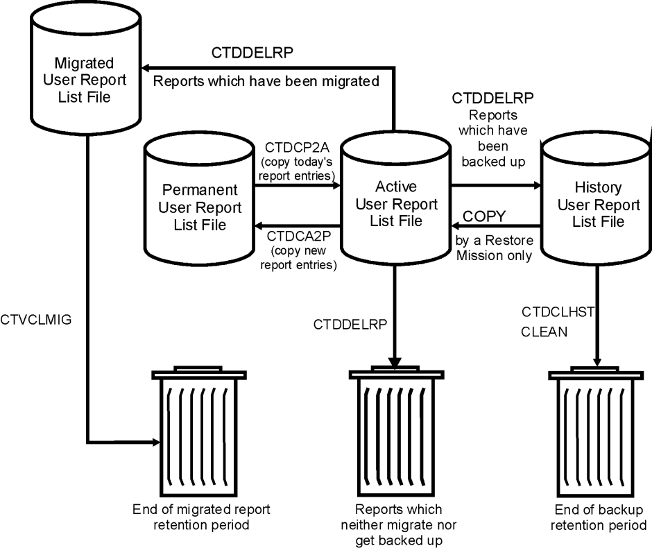
Repository Maintenance
The Control‑D Repository consists of the following files:
-
Active Missions file (AMF)
-
Communications file (COM)
-
User Report List files:
Active User Report List file
Permanent User Report List file
History User Report List file
Migrated User Report List file for Control‑V
All the files are self‑maintained by the New Day procedure or by utilities such as CTDDELRP and CTDCLHST. Self-maintenance is usually performed on a daily basis. Additional utilities are used for expanding file sizes, physical reorganization, and so on. This section details how to use these utilities.
Expanding Control-D Files
The following Control‑D files can be expanded using ICE:
-
Active Mission File (AMF) (For the procedure, see the Control-D customization section in the INCONTROL for z/OS Installation Guide: Customizing.)
-
Communication File (COM)
Perform the following steps to expand Control‑D files:
-
Close all monitors. For example, to shut down the ControlD monitor, issue operator command
CopyP CONTROLD. -
Rename the old file (that you want to expand).
-
Using ICE, select Customization. Enter CTD in the Product field, select Product Customization, and then select Major Step 6, "Customize Control-D Dataset Parameters." Perform the steps in order for each file you want to expand.
-
Perform minor step 1, "Customization Instructions," which provides an overview of the process.
-
Perform minor step 2, ControlD Dataset Parameters, which lets you specify values that ICE uses to calculate the appropriate file size. During this step, specify a question mark (?) in any parameter field for help. Modify only the parameters relevant for the files you want to expand
-
AMFSIZE for the Active Mission File;
-
COMSIZE for the Communication File
-
-
Perform minor step 3, Save Parameters into Product Libraries, to save the parameter values that you specified in minor step 2.
-
Minor steps 4 through 6 run jobs that perform the expansion. Perform only those steps relevant to the files you want to expand.
User Report List File Housekeeping
Perform the following User Report List file housekeeping activities as required:
-
reorganize the files
-
dynamically sort the Active User Report List File
-
rebuild the Index component
-
recover a damaged file
Reorganizing the Files
The Data and Index components of an IOA Access Method file may extend beyond one physical dataset. When an IOA Access Method file extends to many physical datasets, processing may degrade due to fragmentation overhead. In this case, it is recommended that you reorganize the IOA Access Method file so that the primary and secondary extent datasets are larger. Perform the following steps:
-
Stop all ControlD related activities (ControlD monitor, online activities, batch utilities).
-
Run utility IOADUL to unload the contents of the Data component to a sequential file. For an example, see member CTDUFDUL in the ControlD JCL library.
-
Increase the value specified for parameter SPACE in the relevant DEFxxx and DEFxxxI definition members to specify larger primary and secondary extents. Change this parameter in the definition members of both the Index and Data components.
-
Delete all dataset extents of the Index and Data components. Perform this step with caution. For an example, see member CTDUFDEL in the ControlD JCL library.
-
Run the IOADBF utility with parameter FUNC=INIT to allocate and format the new file’s components using the new parameters. Activate the utility twice, once for the Data component and a second time for the Index component. For an example, see member CTDUFDBF in the ControlD JCL library.
-
Run the IOADLD utility to reload contents of the data component from the sequential dataset previously produced by the IOADUL utility. Run the CTDDIB utility to rebuild the index component. For an example, see the CTDUFRST member in the ControlD JCL library.
-
Restart ControlD and all other related activities.
Dynamic Sorting of the Active User Report List File
The Active User Report List file can be dynamically sorted by utility IOADBSR.
The Index component of the IOA Access Method file functions as a balanced tree index. The Control‑D monitor can optionally sort the Data component of the Active User Report List file so that the physical order of the records is the same as the logical order of the Index component. This automatically provides increased I/O performance benefits for users of the Control‑D Online Viewing facility and utilities such as CTDDELRP.
Dynamic sorting of the Active User Report list file does not inhibit the simultaneous execution of other Control‑D activities, such as decollation, printing, backup and restore mission processing, or access to online user facilities.
Although dynamic sorting allows other processes to be performed concurrently on the same file components, INCONTROL for z/OS supplies a set of Sort Control parameters that can be specified to execute dynamic sorting at a time of day and at intervals when access to Control‑D file components is at a minimum. Dynamic sorting is disabled by default. For a description of the Sort Control parameters and Dynamic sorting, see the IOADBSR utility and the ENABLE parameter in the INCONTROL for z/OS Utilities Guide.
Dynamic sorting of the Active User Report list file is enabled and controlled by the parameters specified in member DBSRTPRM in the Control‑D PARM library (allocated to DD statement DASORTPR in the Control‑D monitor’s procedure JCL).
IOA Access Method files can also be sorted by executing utility IOADBSR as a batch job. For a description of the IOADBSR utility, see the INCONTROL for z/OS Utilities Guide.
Rebuilding the Index Component
To rebuild the Index component, perform the following steps:
-
Stop all ControlD related activities (ControlD monitor, online activities, batch utilities).
-
Run the CTDDIB utility to rebuild the Index component from the Data component. For an example, see member CTDUFDIB in the ControlD JCL library.
-
Restart ControlD and all other related activities.
Recovering a Damaged File
If dual mirror image file processing is used, it is possible to immediately recover a damaged file. The dual file is an exact copy of the main file. The recovery procedure uses utility IOADCPY to copy the entire dual file to the main file or vice versa. Before starting the recovery procedure, make a backup copy of the main file and the Dual file.
If the Main file is damaged, perform the following recovery steps:
-
Stop all ControlD related activities (ControlD monitor, online activities, batch utilities).
-
Delete all extents of the Data component of the main copy only. For example, to delete all the extents of the Active User Report List file, list all the files with prefix CTD.ACT.E* and delete them.
-
Run the IOADCPY utility with parameter SUFFIX set to the Dual file (D000). For an example, see sample member CTDUFCPY in the ControlD JCL library.
-
Rebuild the Index component (see the preceding topic).
-
Restart all ControlD activities.
If the Dual file is damaged, perform the following recovery steps:
-
Stop all ControlD related activities (ControlD monitor, online activities, batch utilities).
-
Delete all extents of the Data component of the Dual copy only. For example, to delete all the extents of the ControlD Active User Report List file, list all the files with prefix CTD.ACT.D* and delete them.
-
Run the IOADCPY utility with parameter SUFFIX set to the Main file (E000). For an example, see sample member CTDUFCPY in the ControlD JCL library.
-
Rebuild the Index component.
-
Restart all ControlD activities.
For more information about IOA Access Method utilities for User Report List files, see the INCONTROL for z/OS Utilities Guide.
SMF Accounting
Control‑D produces several types of SMF records that provide comprehensive accounting and chargeback information.
-
An SMF record for each printed report is produced during deferred printing. The record number is specified in parameter SMF=nnn in member CTDPARM in the IOA PARM library. The record can be disabled by setting SMF to NO in member CTDPARM. The structure of the record is described in macro CTDSMF in the IOA MAC library. ControlD Exit CTDX006 receives each record before it is written to SMF files. The exit can change or add fields to the record.
-
An SMF record can be produced for each printed report during immediate printing. This is triggered by Optional Wish WD0892 in member IOADFLT in the IOAENV library or IOADFLTL in the PARM library. The record number and structure are identical to those provided for deferred printing.
-
An SMF record describing activity of an online user is written during logoff operation performed under the IOA online monitor. The record contains CPU/EXCP consumed by the current user and also the number of performed operations (view, print, restore and delete requests). The structure of the record is described in macro CTDSFO in the IOA MAC library. The SMF ID of the record is defined by the SMFONL parameter in the IOAPARM parameter member. The parameter value can be changed using the following steps in the IOA Customization facility of ICE:
-
Major Step: 1 IOA Post-Installation
-
Minor Step: 1 Update IOA Parameters
-
Minor Step: 4 Parameter Verification
-
Minor Step: 5 Save Parameters into Product Libraries
The record can be changed or discarded by IOA Exit IOAX006 before it is written to SMF under SMF function.
-
-
An SMF record created during a decollation process contains the number of pages and lines processed by a decollation mission, the CPU utilized by it, the number of report entries built, and so on. The structure of the record is described in macro CTDSF2 in the IOA MAC library. The record can be changed or discarded by the Control-D Exit CTDX022D before it is written to SMF. The SMF ID of the record is defined by the SMFDEC parameter in the CTDPARM parameter member. The parameter value can be changed using the following steps in the Control-D Customization facility of ICE:
-
Major Step: 1 CTDPARM Post-Installation
-
Minor Step: 1 CONTROL-D Operational Parameters
-
Minor Step: 8 Parameter Verification
-
Minor Step: 9 Save Parameters into Product Libraries
-
-
An SMF record is produced when each request from the IOASMON CDAM Archive Server completes execution. The SMF record number is specified in parameter SMF=nnn in the IOASPRM member in the IOA PARM library. Generation of this SMF record can be disabled by setting SMF=NO in the IOASPRM member. The structure of this SMF record is described in macro CTVSMF in the IOA MAC library. ControlV Exit CTVX002 receives each record before it is written to the SMF file. The exit can add or change fields in the record and can prevent the record from being written.
-
An SMF record describing activity of Control-D/WebAccess user is written by Control-D Application Server. The record contains CPU consumed by the current user and also the number of operations performed (view, print and restore requests). The structure of the record is described in macro CTDPSMF in the IOA MAC library. The SMF ID of the record is defined by the SMFWA parameter in the CTDPARM parameter member. The parameter value can be changed using the following steps in the CTD Customization facility of ICE:
-
Major Step: 1 CTDPARM Post-Installation
-
Minor Step: 1 CONTROL-D Operational Parameters
-
Minor Step: 8 Parameter Verification
-
Minor Step: 9 Save Parameters into Product Libraries.
The record can be changed or discarded by IOA Exit CTDX024 before it is written to SMF under SMF function.
-
-
All SMF recording options are shown in the following table:
Table 178b SMF recording options
|
Process |
SMF parameter |
IOA PARM Member |
Address space |
IOA MAC Macro |
User Exit before SMF is written |
SMF Modify command |
|---|---|---|---|---|---|---|
|
Deferred Printing |
SMF |
CTDPARM |
CTDPRINT Control-D Print Monitor |
CTDSMF |
CTDX006 |
No |
|
Immediate Printing |
SMF WD0892 |
CTDPARM IOADFLTL |
IOAOMON IOA Online Monitor, |
|||
|
Decollation Mission |
SMFDEC |
CTDPARM |
CTDTROLD Control-D Monitor |
CTDSF2 |
CTDX022 |
Yes |
|
Online User Activity |
SMFONL |
IOAPARM |
IOA Online Monitor, TSO session |
CTDSMFO |
IOAX006 |
Yes |
|
CTD/WA User Activity |
SMFWA |
CTDPARM |
IOAAS Control-D Application Server |
CTDSMFW |
CTDX024 |
Yes |
|
Archive Activity |
SMFV |
IOASPRM |
IOASMON CDAM |
CTVSMF |
CTVX002 |
No |
The SMF modify command allows the Control-D Decollation Monitor, IOA Online Monitor and Control-D Application Server to re-activate the SMF recording after error. This way SMF recording can be activated again without requiring the corresponding address spaces to be restarted.
The SMF modify operator command syntax for Control-D Decollation Monitor and IOA Online Monitor is as follows:
F asname,SMF where asname is the address space name.
The SMF modify operator command syntax for Control-D Application Server is as follows:
F IOAGATE,MODASID[=nn] MODAPPL D SMFwhere nn is the decimal sequential ASID number of the Control-D Application Server address space to which the modify command is submitted. The modify command is broadcast to all active Application Server address spaces if the ASID number ‘=nn’ is omitted.
Deleting IOA Access Method Files
When deleting IOA Access Method files (for example, for reorganization or reallocation with new SPACE parameters), delete all existing extents, not just the first (*.E000) extent. Use job CTDUFDEL for this purpose.
 Communities
 Support Center
 YouTube
 Twitter
 Facebook
 LinkedIn