Control-M
Overview
Operator Command Quick Reference
The following is a list of some of the more common Control‑M Monitor operator commands explained in this chapter.
In these commands, CONTROLM represents the name of the Control-M monitor.
The CTMPLEX Monitor column indicates on which monitor the operator command can be run in CTMPLEX mode. Possible values are:
-
GSM - On the Global Sysplex Manager (GSM) system only.
-
Both - On both the GSM and LSM systems.
-
None - Not relevant to CTMPLEX. For example, CMEM has its own monitor and does not use the ControlM monitor.
Table 85 Operator Command Quick Reference
|
Category and Task |
Command |
CTMPLEX Monitor |
|---|---|---|
|
General Operations |
||
|
S CONTROLM |
Both |
|
|
P CONTROLM |
Both |
|
|
F CONTROLM,INTERVAL=xx |
GSM |
|
|
F CONTROLM,SHOWPARM |
Both |
|
|
F CONTROLM,NEWPARM |
|
|
|
F CONTROLM,LISTDD |
Both |
|
|
F CONTROLM,LISTVDET F CONTROLM,LISTVSUM |
Both |
|
|
F CONTROLM,RELOAD=userExit |
GSM |
|
|
Stopping Control-M monitors - Using STOPALL to shut down the Control-M monitor |
F CONTROLM,STOPALL |
GSM |
|
F CONTROLM,PERFDATA=NOW |
Both |
|
|
F CONTROLM,PERFDATA=nnnn |
Both |
|
|
Quiesce Time Management |
||
|
Scheduling Quiesce Time - |
F CONTROLM,QUIESTIME=hhmm |
GSM |
|
Stopping submission of any Job |
F CONTROLM,QUIESTIME=NOW |
GSM |
|
Cancelling requests for Quiesce Time |
F CONTROLM,QUIESTIME=OFF |
GSM |
|
Displaying the current status of QUIESTIME |
F CONTROLM,QUIESTIME=DISPLAY |
GSM |
|
Quiesced Resource Management |
||
|
Scheduling quiesced qualitative resources - Activating and Deactivating Quiesced Quantitative Resources |
F CONTROLM,QUIESQRES=resource-name,hhmm |
GSM |
|
Stopping the use of a quantitative resource |
F CONTROLM,QUIESQRES=resource-name,NOW |
GSM |
|
Cancelling previous requests for quiesced resources |
F CONTROLM,QUIESQRES=resource-name,OFF |
GSM |
|
Displaying the current status of QUIESQRES |
F CONTROLM,QUIESQRES=resource-name,D |
GSM |
|
Destination Tables |
||
|
F CONTROLM,NEWDEST=member |
GSM |
|
|
F CONTROLM,NEWMAILDST |
GSM |
|
|
Loading and Refreshing the SNMP Destination Table (SNMPDEST) |
F CONTROLM,NEWSNMPDST |
GSM |
|
Reloading the WLMSCTBL table |
F CONTROLM,NEWLMSCTBL |
GSM |
|
Deadline Scheduling and Job Network Dependencies |
||
|
Refreshing DUE OUT times - Refreshing Deadline Scheduling and Job Network Dependencies |
F CONTROLM,DEADLINE |
GSM |
|
Shifting the DUE OUT time forward - Shifting DUE OUT Times for Control-M Jobs |
F CONTROLM,SDOUT=+nnn |
GSM |
|
Shifting the DUE OUT time backward -Shifting DUE OUT Times for Control-M Jobs |
F CONTROLM,SDOUT=-nnn |
GSM |
|
Refreshing PRIORITY values - Refreshing Deadline Scheduling and Job Network Dependencies |
F CONTROLM,PROP |
GSM |
|
Refreshing both the DEADLINE (DUE OUT) times and the PRIORITY values - Refreshing Deadline Scheduling and Job Network Dependencies |
F CONTROLM,REFSCHED |
GSM |
|
Refreshing the List of Dependent Jobs in the Job Dependency Network File - Refreshing Deadline Scheduling and Job Network Dependencies |
F CONTROLM,NET |
GSM |
|
Simultaneously refreshing the DEADLINE (DUE OUT) times, PRIORITY values, and the List of Dependent Jobs in the Job Dependency Network (NET) - Refreshing Deadline Scheduling and Job Network Dependencies |
F CONTROLM,REFALL |
GSM |
|
Security |
||
|
F CONTROLM,NEWSECDEF |
GSM |
|
|
Automatic Tape Adjustment Facility |
||
|
Refreshing the UNITDEF Table (Unit Definition Table) |
F CONTROLM,NEWUNITDEF |
GSM |
|
Trace Facility |
||
|
Using the Control‑M Internal Trace facility - Problem Determination using the Internal Trace Facility |
F CONTROLM,TRACE=level |
GSM |
|
Supporting Interfaces |
||
|
F CONTROLM,SAPI=NO |
GSM |
|
|
Switching from PSO to SAPI Support -Switching from SAPI to PSO Support |
F CONTROLM,SAPI=YES |
GSM |
|
F CONTROLM,IDL=<IDLModifyCommand> |
Both |
|
|
AutoEdit Variables and the Cache |
||
|
Reloading AutoEdit definitions to cache - Loading %%GLOBAL Members to Cache |
F CONTROLM,AECACHE=RELOAD |
GSM |
|
Reloading AutoEdit definitions using new list members to cache - Loading %%GLOBAL Members to Cache |
F CONTROLM,AECACHE= |
GSM |
|
Stopping cache until AECACHE=RELOAD - Loading %%GLOBAL Members to Cache |
F CONTROLM,AECACHE=STOP |
GSM |
|
Newday Operations |
||
|
Modify the number of intervals to wait for Newday |
F CONTROLM,NEWDAYWT= |
GSM |
|
F CONTROLM,NEWDAY=expression |
GSM |
|
|
Optimization Commands |
||
|
F CONTROLM,LOAD-INDEX <commands> |
Both |
|
|
F CONTROLM,WLLIST |
GSM |
|
|
F CONTROLM,WLREFRESH |
GSM |
|
|
CMEM Facility |
||
|
Manually Activating the CMEM Monitor -Activating the CMEM Facility |
S CTMCMEM |
None |
|
Shutting Down the CMEM Facility - Deactivating the CMEM Facility |
F CTMCMEM,STOP |
None |
|
Replacing an Active CMEM Monitor - Replacing an Active CMEM Monitor |
S CTMCMEM |
None |
|
Replacing the Active CMEM Executor Modules -Replacing the Active CMEM Executor Modules |
F CTMCMEM,RELOAD=module |
None |
|
Manual Loading of Rules - Manual Loading of Rules using Operator Commands |
F CTMCMEM,C=library(table) |
None |
|
Replacing All CMEM Rule Tables in All CPUs - Replacing All CMEM Rules Tables in All CPUs |
F CONTROLM,NEWCONLIST |
None |
|
F CTMCMEM,D=library(table) |
None |
|
|
F CTMCMEM,DISPLAY[=DETAIL] |
None |
|
|
F CTMCMEM,LOG=mode |
None |
|
|
F CTMCMEM,INTERVAL=nn |
None |
|
|
F CTMCMEM,NEWSECDEF |
None |
|
|
F CTMCMEM,TRACE=nn |
None |
|
|
F CTMCMEM,USAGESTATS |
None |
|
|
Journaling |
||
|
F CONTROLM,JOURNAL=ENABLE |
GSM |
|
|
F CONTROLM,JOURNAL=DISABLE |
GSM |
|
|
AJF Space Reuse Facility |
||
|
Activate deletion for space reuse of jobs copied to History AJF - History file processing for AJF space reuse |
F CONTROLM,HISTALOC=ENABLE |
GSM |
|
Deactivate deletion for space reuse of jobs copied to History AJF - History file processing for AJF space reuse |
F CONTROLM,HISTALOC=DISABLE |
GSM |
|
CTMPLEX Facility |
||
|
Start the Control-M monitor on any system. The monitor becomes either a GSM or LSM monitor depending on whether there are other Control-M monitors of the same CTMPLEX. - Controlling CTMPLEX |
S CONTROLM |
GSM |
|
Stop any LSM (when issued on the system where an LSM runs) or stop the entire CTMPLEX (when issued on the system where the GSM runs). - Controlling CTMPLEX |
P CONTROLM |
GSM |
|
Activates or inactivates Work Balancing mode, overriding the value of parameter BALANCEM - Controlling CTMPLEX |
F CONTROLM,BALANCE=YES|NO |
GSM |
|
Stops all LSM monitors. The GSM monitor continues working in regular (not CTMPLEX) mode. - Controlling CTMPLEX |
F CONTROLM,STOPPLEX |
GSM |
|
Stops the GSM. - Controlling CTMPLEX |
F CONTROLM,STOPGSM |
GSM |
|
Displays information about all monitors (GSM and LSMs) of the CTMPLEX. - Controlling CTMPLEX |
F CONTROLM,LISTPLEX |
GSM |
|
Resumes CTMPLEX processing after environmental errors related to the CTMPLEX Coupling facility structure occur. - Controlling CTMPLEX |
F CONTROLM,STARTPLEX |
GSM |
|
Displays information about the GSM from an LSM - Controlling CTMPLEX |
F CONTROLM,WHOGLOBAL |
Both |
|
Issues a diagnostic dump (to any of SYS1.DUMPxx datasets) in order to obtain the contents of the CTMPLEX Coupling facility structure. - Controlling CTMPLEX |
F CONTROLM,DUMPPLEX |
GSM |
Basic Operations
This section discusses the following basic operations:
Special Newday Parameters
The Newday procedure is normally executed once daily at the time specified by the DAYTIME parameter in CTMPARM. Under certain circumstances (such as disaster recovery), you might need to execute Newday at a different time or to skip a Newday run. The NEWDAY command options described in this section enable you to accomplish such non-standard tasks.
WARNING: The Control-M for z/OS User Guide describes the deprecated RETRO parameter. (If a job did not run as scheduled, a value of RETRO=Y results in the job automatically running at a later time.) Even though RETRO=Y still works as designed, BMC recommends that you remove RETRO expressions from all job scheduling definitions. Doing so will also enable you to take advantage of all of the options described in the table below. If you did not remove RETRO=Y expressions from job scheduling definitions, do NOT include date parameters in special Newday commands that you run.
Special Newday commands have the following syntax:
F CONTROLM,NEWDAY=expressionwhere expression is one of the options described in the table below.
Table 86 Newday Special Parameters
|
Parameter |
Description |
|---|---|
|
SKIP |
Skip the next Newday process. Although Newday does not run at the time indicated by the DAYTIME parameter in CTMPARM, the AJF is updated as if Newday ran. Under certain circumstances, the Control-M monitor initiates Newday processing immediately upon startup. To skip Newday processing at startup, start the Control-M monitor with the following command: Copy
The SKIP option is useful in disaster recovery scenarios in case you need to not initiate the Newday procedure upon start-up. See Example 1 - Continue execution at recovery site. When Newday is bypassed at startup by NEWDAY=SKIP, the next upcoming Newday will run at its normal time, unless another NEWDAY=SKIP is issued. |
|
hhmm|NOW |
NOW—run Newday immediately. hhmm—run Newday at the next occurrence of hhmm. If hhmm is earlier than the current time, the command runs NEWDAY the following day at hhmm. The next day’s regularly scheduled Newday procedure is also executed. The command F CONTROLM,NEWDAY=hhmm does not change the value DAYTIME in CTMPARM. |
|
hhmm[,date] |
Run Newday at time hhmm (or NOW). If date is not specified, the current ODATE is used. Otherwise, date determines the ODATE. According to the value of the DATETYP parameter in IOAPARM, use the appropriate of the following date formats: yymmdd, ddmmyy, mmddyy. This option is useful to reschedule a workload after the computer has not been working for one or more days due to holiday, hardware failure, and so on, using the original scheduling date for each Newday iteration. See Example 2 — system down for three days. |
|
hhmm,RERUN |
Rerun Newday with the current ODATE at time hhmm (or NOW). |
|
hhmm,ORDERONLY[,date] |
Rerun the Newday process except for the compress phase at the time specified (hhmm) or now, if no time is specified. If date is not specified, the current ODATE is used. Otherwise, date determines the ODATE. This option is useful when the job ordering phase of the Newday procedure terminated prematurely without ordering its full complement of jobs. See Example 4 - Newday processing abended during job ordering. To use this option, ensure that Enhanced Daily Checkpointing is implemented. For more information, see Date Control Records and Enhanced Daily Checkpointing. |
|
hhmm,FORMATONLY |
Compress the AJF at time hhmm (or NOW). Control-M monitor enters suspend mode during this AJF compression, and resumes execution at its conclusion. There is no need to shut down Control-M monitor (which is required when you use the CTMCAJF utility COMPRESS command). |
Examples
This section describes several scenarios that call for running the Newday procedure with special parameters.
Example 1 - Continue execution at recovery site
The system date at a disaster recovery site differs from the date at the production site in a way that starting Control-M monitor at the recovery site would trigger Newday processing for the wrong day. Enter the following command to start Control-M without running Newday:
S CONTROLM,NEWDAY=SKIPExample 2 — system down for three days
The system was down for three days. After starting Control-M monitor according to "Example 1 — continue execution at recovery site," you probably need to run Newday for each of the three days in succession. If so, then in Control-M monitor, enter the following command three times, specifying the appropriate ODATE value for date each time (and waiting for job processing to conclude between each repetition):
F CONTROLM,NEWDAY=NOW,dateExample 3 — system error requires restart of Newday processing
Due to an error in JES, all of the jobs that Newday submitted ended with JCL errors. After resolving the JES issue and clearing the AJF of jobs submitted, enter the following command to rerun Newday:
F CONTROLM,NEWDAY=NOW,RERUNExample 4 - Newday processing abended during job ordering
If Newday processing abended during job ordering, and ODATE has not changed, enter the following command to restart job ordering:
F CONTROLM,NEWDAY=NOW,ORDERONLYActivating the Control-M Monitor
The Control‑M monitor usually operates 24 hours a day as a started task (STC). Usually the monitor is automatically activated as part of the IPL process. To activate the monitor manually, use the operator command
S CONTROLMIf the monitor is successfully activated, the following message is displayed on the operator console:
CTM100I CONTROL‑M MONITOR STARTEDWhen Control‑M operates in standalone mode, once the Control‑M monitor is active, if you try to activate an additional Control‑M monitor with the same IOA components in the same computer environment where a Control‑M monitor is active, the new (that is, additional) monitor immediately shuts down and an appropriate message is issued.
It is possible to activate more than one Control‑M monitor in the same computer environment (for example, PROD and TEST version) by defining a different IOA environment (and a different QNAME) for each monitor. For more information see the Control‑M chapter of the INCONTROL for z/OS Installation Guide: Installing.
Under CTMPLEX configuration, more than one Control‑M can be active under an IOA environment. For more information about Control‑M in CTMPLEX configuration see CTMPLEX: Control-M for the Sysplex.
You can issue Control‑M operator commands that are executed immediately when you start the Control‑M monitor. You do this by specifying the operator command in parentheses as the fourth positional operator in the START command.
Activate the Control-M monitor in QUIESCE mode by issuing the following command:
S CONTROLM,,,(QUIESTIME=NOW)No jobs will be submitted by Control-M until you issue the QUIESTIME=OFF command.
Activate the Control-M monitor in QUIESCE mode and simultaneously instruct Control-M to skip the next NEWDAY process (see Special Newday Parameters.) by issuing the following command:
S CONTROLM,,,(QUIESTIME=NOW),NEWDAY=SKIPNo jobs will be submitted by Control-M until you issue the QUIESTIME=OFF command.
Shutting Down the Control-M Monitor
To shut down the Control‑M monitor, use the P CONTROLM operator command.
After a few seconds (up to a minute), the Control‑M monitor shuts down and the following messages are displayed on the operator console:
CTM107I SHUT DOWN UPON REQUEST FROM OPERATOR
CTM120I Control‑M MONITOR SHUTTING DOWN
In case of emergency, you can cancel the Control‑M monitor. However, you should avoid doing this unless absolutely necessary, because cancelling the monitor may corrupt the database in the Active Jobs file, Conditions file, and Log file. There are times when cancelling the Control-M monitor is unavoidable (for example, when there are severe problems in JES). However, in such cases, BMC recommends that the user first try to QUIESCE Control-M, if possible. In this way, you can minimize the activity taking place within Control-M before the cancellation, and thereby minimize the potential for corruption.
When canceling the monitor, as in the case where the Control-M monitor is hung, a system (SVC) dump of the Control-M Monitor address space should be taken. To do this:
-
Enter MVS console command 'DUMP'
-
Specify JOBNAME or ASID of the monitor
-
Specify parameter SDATA=(CSA,GRSQ,SUM,RGN,TRT)
The SVC dump should be taken before trying to stop/cancel the Monitor.
When you shut down the Control‑M monitor, all other Control‑M facilities (for example, CMEM), IOA Online monitors, and Online facility sessions can remain active.
Modifying the Control-M Sleeping Interval
Periodically, at a predefined interval, Control‑M "wakes up" and checks what it has to do. This interval is set using a Control‑M installation parameter and can be changed by the INCONTROL administrator. In addition, the sleep interval can be altered by the
F CONTROLM,INTERVAL=ss[.th]operator command.
In this command
-
ss is the interval in seconds
-
th is the interval in hundredths of seconds
The interval should be modified by automatic commands invoked by the Control‑M monitor itself according to set conditions and time ranges, and not manually by the operator.
At most sites, the interval should be longer during the day (when fewer batch production jobs are executing) and shorter during the night. The minimum sleep interval is 0.1 seconds.
When the modification is received by Control‑M, the following message is displayed on the operator console from which the modify command was issued:
CTM123I Control‑M INTERVAL IS SET TO ss.th SECONDSDisplaying Control-M Installation Parameters
Control‑M installation parameters contain general information about your system.
To display the values of some of the more important parameters, issue the following operator command:
F CONTROLM,SHOWPARMDynamically Refreshing Control-M Parameters
The CTMPARM installation parameters table can be refreshed dynamically, that is, without stopping and restarting the Control‑M Monitor, using the following operator command:
F CONTROLM,NEWPARMAfter the command has been executed, the Control‑M Monitor uses the new installation parameters from CTMPARM.
If Control‑M/Restart is installed, NEWPARM also refreshes CTRPARM, and the Monitor then starts to use the new CTRPARM parameters.
Almost all Control‑M and all Control‑M/Restart installation parameters can be dynamically refreshed in this way. For those Control‑M parameters that cannot, the original values are not replaced and the Control‑M Monitor continues to use their original values. These Control‑M parameters are:
-
AJFSIZE
-
ARMELMNT
-
AUTOTAPE
-
CTMPLEX
-
ENHNJE
-
JRNL
-
MVBO
-
NONSWAPM
-
NEWDAYIM
-
OPTMODE
To replace these values that cannot be refreshed dynamically, do the following:
-
Stop the ControlM Monitor.
-
Replace the values in the CTMPARM member.
-
Restart the Monitor.
Displaying a List of Allocated Datasets
To display the currently allocated datasets, enter the command F CONTROLM,LISTDD.
The currently allocated datasets are passed to your console and to the JOBLOG of the Control‑M Monitor.
Displaying Storage Maps for the Control-M Monitor
A pair of MODIFY commands provide you with information about storage memory allocations. These reports are issued into the file referred by the DD card DAPRENV. You can choose between a detailed report or a summary report.
To display a detailed storage map by TCB storage key and subpool, specify the following operator command:
F CONTROLM,LISTVDETEvery allocated block is listed by TCB and subpool number. The following information is displayed on the operator console from which the modify command was issued:
-
TCB
-
SUBPOOL: Subpool number
-
FROMADDRESS: Address from which the dataset is allocated
-
LENGTH: Size of the dataset (both above and below the line)
To display a summary storage map, specify the following operator command:
F CONTROLM,LISTVSUMTotals for all allocated blocks are listed.
Dynamically Reloading User Exits
Control-M user exits can be dynamically reloaded without the need to recycle the Control-M Monitor by using the operator command:
F CONTROLM,RELOAD=userExit.where userExit = CTMX001, CTMX002, CTMX003, CTMX004, or CTMX015.
For security purposes, some customers choose to link-edit user exit CTMX001 into load module CTMJOB or user exit CTMX002 into load module CTMSUB, or both. The RELOAD operator command will only reload these user exits if they have not been link-edited into load modules CTMJOB and CTMSUB, respectively. Before reloading these user exits, a check is made that will cause the RELOAD command to abort if these exits are link-edited directly into the aforementioned load modules.
The RELOAD command fully supports a CTMPLEX environment. All local (LSM) monitors will automatically reload the relevant user exits.
Due to the efficient way Control-M subtasks operate, the actual RELOAD of the user exits and the resulting messages, CTMR0AI and CTMR09E, may not occur until a job is ordered or a DO FORCEJOB is executed by Control-M.
Dynamically Refreshing CTMPLEX Parameters
The System Entries parameters of the CTMPLEX parameters member can be dynamically refreshed using the following operator command:
F CONTROLM,NEWPLEXThe parameters that can be refreshed in this way are the System Entries parameters of the CTMPLEX parameters member. However, the General parameters are not processed by this command.
The General parameters of the CTMPLEX parameters member can only be refreshed by one of the following methods:
-
using the STOPPLEX and STARTPLEX commands
-
stopping and then restarting the ControlM Monitor
Using STOPALL to shut down the Control-M monitor
The STOPALL command may be also used to shut down Control-M. In a non-CTMPLEX environment, this command works in the same way as the P CONTROLM operator command. In a CTMPLEX environment, this command stops all Control-M monitors (both the Global and all Locals).
To stop one or more Control-M monitors, enter the following operator command:
F CONTROLM,STOPALLSetting a Planned Shutdown Time (Quiesce Time)
Setting the Control‑M monitor planned shutdown time (QUIESTIME) stops the submission of jobs that, according to their average execution time, cannot finish before the specified QUIESTIME. Setting a QUIESTIME only affects submission processing and not other Control‑M functions, such as post-processing.
QUIESTIME is not applied to jobs that have already issued an ELIGIBLE FOR RUN message in the log. Such jobs are submitted as scheduled.
QUIESTIME is set by the operator command
F CONTROLM,QUIESTIME=xxxxIn this command, xxxx is one of the values described in the following table:
Table 87 QUIESTIME Values
|
Value |
Description |
|---|---|
|
hhmm |
Where hh is the hour, based on a 24-hour clock mm is the minute The planned shutdown time before which, based on their execution time, jobs must end. If any jobs cannot end by that time, QUIESTIME stops their submission. A QUIESTIME command using this value supersedes any previous shutdown time setting. |
|
NOW |
Immediately stops the submission of all jobs. |
|
OFF |
Cancels any QUIESTIME requests that are currently active. |
|
D |
Displays the current status of QUIESTIME, in the form of messages CTML19I and RUNL19I. Message CTML19I appears in the IOA Log in the form Copy
and message RNL19I appears in the System Log in the form Copy
where yyyy is hhmm, NOW, or OFF. |
By default, QUIESTIME affects both tables and jobs. However, if the IGNQTMGR parameter in the CTMPARM member is set to Y, QUIESTIME only affects jobs.
Recycling of the Control-M monitor cancels the previously defined QUIESTIME. The QUIESTIME can be defined when the Control-M monitor is activated with the START command. For more details, see Activating the Control-M Monitor.
Activating and Deactivating Quiesced Quantitative Resources
When a job is ordered by Control-M, the job ordering process checks for any quantitative resources that have been deactivated or are to be deactivated at a later time. If the job requires such a quantitative resource, and if the time that the job is expected to complete is later than the time at which the quantitative resource is deactivated, then the quantitative resource is not assigned to the job, and the job will not run.
The QUIESQRES command enables users to activate and deactivate quantitative resources, and to display the status of those resources.
To display or change the status of a specific resource, enter the following command:
F CONTROLM,QUIESQRES=resource-name,DISPLAY|NOW|OFF|hhmmwhere
-
resource-name is the quantitative resource
-
DISPLAY displays the activation status of the quantitative resource
-
NOW immediately deactivates the quantitative resource
-
OFF immediately reactivates the quantitative resource
-
hhmm deactivates the quantitative resource at the specified time
The current status of all quiesced quantitative resources can be displayed by using an asterisk (*) as the value of the resource-name variable, as shown in the following example:
F CONTROLM,QUIESQRES=*,DAll quiesced quantitative resources can be immediately reactivated by using an asterisk (*) as the value of the resource-name variable, as shown in the following example:
F CONTROLM,QUIESQRES=*,OFFYou can use an asterisk as the value of the resource-name variable only with the DISPLAY and OFF subparameters.
Shout / Mail Facility Destination Table Operations
The IOA Shout and Mail facilities allow the user to specify messages to be sent to various destinations, defined by the following tables:
-
Dynamic Destination Table (IOADEST)
Destinations in a production environment are not necessarily fixed. For example, the TSO logon ID of the shift manager is different in every shift. The Dynamic Destination table enables the user to specify a group name destination and which final destinations it represents.
-
Mail Destination Table (MAILDEST)
Mail destinations consist of names, addresses and groups to whom ControlM can send e–mail messages.
-
SNMP Destination Table (SNMPDEST)
SNMP destinations consist of host names, IP addresses, nicknames, group names, and port numbers where Control-M can send SNMP traps (messages).
For instructions on how to manage these tables, see Shout / Mail Facility Destination Table Administration.
Loading a New Dynamic Destination Table (IOADEST)
When the Control‑M monitor is started, the Dynamic Destination table, IOADEST, is loaded. To replace the Dynamic Destination table, IOADEST, with a new table, use the following operator command:
F CONTROLM,NEWDEST=memberwhere member is the name of the member with the new Dynamic Destination table.
After a few seconds, a message describing the result of the operation is displayed on the operator console from which the modify command was issued.
Loading a New Mail Destination Table
The Mail Destination table contains a list of names, addresses, and groups to whom e–mail messages can be sent.
When the Control-M monitor is started, the Mail Destination table is loaded. Message CTM280I - MAILDEST TABLE WAS LOADED is generated when the Mail Destination table is reloaded successfully.
Refreshing the Mail Destination Table (MAILDEST)
When a name, address or group is added or changed, the Mail Destination table must be reloaded by using the following command:
F CONTROLM,NEWMAILDSTA new Mail Destination table replaces the existing one, and the following message is displayed on the operator console from which the modify command was issued when the monitor resumes job processing:
CTM280I MAILDEST TABLE WAS RELOADED.If the table is not found, the following message is displayed:
CTM281W MAILDEST TABLE WAS NOT FOUND IN ANY LIBRARY REFERENCED BY DD STATEMENT DAPARM. UNABLE TO SEND SHOUTIf an error occurs while loading or reloading the table, the following message is displayed:
CTM288E ERROR IN PREPARING SHOUT TO MAIL, RC=rcLoading and Refreshing the SNMP Destination Table (SNMPDEST)
When the Control-M monitor is started, the SNMPDEST SNMP Destination table is loaded. The table contains host names, IP addresses, nicknames, group names, and port numbers where Control-M DO SHOUT and SHOUT WHEN can send SNMP traps (messages). When any address or name is added, changed, or deleted, the table should be reloaded with the new one by using the following command:
F CONTROLM,NEWSNMPDSTAfter a few seconds, a message describing the result of the operation is displayed on the operator console.
Refreshing Deadline Scheduling and Job Network Dependencies
A group of operator commands enable you to refresh the calculation of job dependency information and runtime scheduling criteria that impact job flows. The following operator commands are available:
-
To refresh the DUE OUT times of jobs and set optimal deadlines for jobs in flows, issue the following operator command:
CopyF CONTROLM,DEADLINE -
To refresh PRIORITY values of jobs so that jobs in a flow have consistent priorities and no job has a lower priority than any of its successor jobs, issue the following operator command:
CopyF CONTROLM,PROP -
To refresh both the DEADLINE (DUE OUT) times and the PRIORITY values, issue the following operator command:
CopyF CONTROLM,REFSCHED -
To refresh the list of dependent jobs in the Job Dependency Network File, issue the following operator command:
CopyF CONTROLM,NET -
To simultaneously refresh all three types of job dependency information (as done by all three commands: DEADLINE, PROP, and NET), issue the following operator command:
CopyF CONTROLM,REFALL
For more information about the adjustment of job deadlines and propagation of priorities, see "Automatic Job Flow Adjustment" in the Introduction chapter of the Control-M for z/OS User Guide.
Shifting DUE OUT Times for Control-M Jobs
If SHOUT WHEN LATE * is specified in a Control‑M job scheduling definition, a message is issued if the job does not finish executing by the specified DUE OUT time. A large number of such messages may be issued if Control‑M is brought up after it, OS/390, or z/OS was down for a significant amount of time.
These messages can be avoided by shifting the DUE OUT time forward an appropriate amount of time (for example, if Control‑M was down for two hours, shift the DUE OUT time 120 minutes forward).
To shift the DUE OUT time forward or backward, issue the command
F CONTROLM,SDOUT={+|‑}nnnwhere
-
+ and - indicate whether to shift the DUE OUT time forward (later) or backward (earlier), respectively.
-
nnn is the number of minutes to shift the DUE OUT time. From 1 to 999 minutes can be specified.
Jobs with a HELD status are not shifted by the SDOUT operator command.
The SDOUT operator command only works if the REFRESH DEADLINE IOA online command or the DEADLINE operator command (see Refreshing Deadline Scheduling and Job Network Dependencies) was previously issued.
Modifying number of intervals to wait for NewDay
After Control-M monitor issues the message CTM113I Control-M MONITOR <monitor name> NEWDAY PROCESSING STARTED, it waits 30 Control-M sleep intervals for the NewDay started task to start executing. If the NewDay procedure does not start to execute, a CTML03W NEW DAY PROCEDURE NOT DETECTED message is issued, followed by CTML06W REPLY 'R' FOR RESUME OR 'E' FOR END.
The number of intervals to wait is set in the CTMPARM parameter NEWDAY#W, which has a default value of 30. For example, if the Control-M sleep interval is 3 seconds, the monitor waits 90 seconds for the Newday started task to start executing.
The number of intervals can be modified by using the following operator command:
F CONTROLM,NEWDAYWT=<number of intervals>The number of intervals must be a number containing 1 to 4 digits.
When the modification is received by Control-M, the following message is displayed on the operator console where the modify command was entered:
CTM109I THE NUMBER OF INTERVALS TO WAIT FOR THE CONTROL-M DAILY IS SET TO <number of intervals>Refreshing the Control-M Security Cache
Control‑M security modules use a security block to identify each user for which an authority check is performed. The first time a user’s security authorization is checked, Control‑M creates a security block for that user. The security block can then optionally be saved for the next time the user’s security authorization is checked.
Security blocks saved for subsequent checks are kept in the Control‑M security cache.
The Control‑M security cache holds security blocks for the last 30 users to have their security authorization checked.
Changes made to a user’s security authorization (since the last time that user’s security block was created) are not automatically included in the information in the user’s security block in the Control‑M security cache. However if a user’s security authorization has been changed and there is no security block in the Control‑M security cache for that user, changes made to the user’s security authorization is in effect the next time that user’s security authorization is checked.
To immediately include new user authorization information in the Control‑M security cache, refresh the security cache using the following operator command:
F CONTROLM,NEWSECDEFThis command refreshes all user authorization information in the Control‑M security cache.
Issuing Operator Commands using a Job or Started Task
Utility IOAOPR can be used to issue operator commands from MVS, JES2, JES3, VTAM, and so on. It can be activated as a job step or as a started task, and allows full control over when to issue a command, and what to do afterwards. It is also possible to send the command to any computer (because Control‑M can schedule a started task in any computer).
For a description of the IOAOPR utility, see the INCONTROL for z/OS Utilities Guide.
Switching from SAPI to PSO Support
SAPI is the IBM SYSOUT processing subsystem. It is the default SYSOUT processing subsystem for Control‑M when Control‑M is operating under z/OS version 1.1 and later. However, Control‑M continues to maintain support for PSO.
If you encounter a problem associated with job post-processing (for example, jobs not properly identified, unpredictable errors), you can switch from SAPI support to PSO support.
-
To switch from SAPI support to PSO support, issue the operator command:
CopyF CONTROLM,SAPI=NO -
To switch to SAPI support from PSO support, issue the operator command:
CopyF CONTROLM,SAPI=YES
For more information about post-processing, see in the introduction chapter in the Control‑M for z/OS User Guide.
Loading %%GLOBAL Members to Cache
%%GLOBAL members can be placed in cache memory from where they can be accessed as needed. If the members are placed in cache, the JCL accesses the contents from the cache, instead of accessing the members themselves.
This can be very advantageous if many jobs access %%GLOBAL members, because each access of the member increases I/O and processing overhead. Only those %%GLOBAL members that are specifically requested are loaded to cache.
Requests are generally made by listing the desired %%GLOBAL members in a special cache list member in the DAGLOBAL library. This cache list member (default name: CACHLST) is pointed to by parameter AECACHL in member CTMPARM in the IOA PARM library.
Use the following format to list members in the cache list member:
%%GLOBAL memnamewhere memname is the name of the %%GLOBAL member pointed to by DD statement DAGLOBAL.
The cache list member can optionally contain the following control statement as its first non-comment statement:
%%RESOLVE ALLCACHEThis control statement affects AutoEdit processing only if an AutoEdit variable has not been resolved by searching the %%GLOBAL members identified in the job. The statement instructs Control‑M to continue the variable resolution process by checking all members loaded into cache. Members in cache are searched in the same sequence they are listed in the cache list member.
%%GLOBAL members are loaded to cache:
-
In the Control-M monitor's address space, at the time of Control-M startup.
-
In the online address space, when the user performs AutoEdit simulations (options 2.%, 3.%, or 6.M2 ), or enters a JCL edit session (2.J or 3.J).
-
At the end of the option processing, the AutoEdit cache is deleted.
-
In the batch AutoEdit simulation job.
The following commands can be used between Control-M startups, and affect only the Control-M monitor's cache processing.
To reload %%GLOBAL members to cache, specify the reload command in either of the following formats:
F CONTROLM,AECACHE=RELOAD
F CONTROLM,AECACHE=RELOAD(membername)
Each of these formats deletes the current %%GLOBAL members from cache, and then (re)loads to cache the %%GLOBAL members listed in the cache list member.
If the command is specified without a member name, the name of the cache list member that was last loaded is used. This format is especially useful if there are changes to the list of %%GLOBAL members in the cache list member and/or changes to the contents of the currently loaded %%GLOBAL members.
If the command is specified with a member name, the member name must identify a cache list member in DAGLOBAL (other than the currently active cache list member).
To stop using AutoEdit cache, issue the following command:
F CONTROLM,AECACHE=STOPAccumulating performance data
Various components of Control‑M collect performance related data. The accumulated data is written to SMF records. The records are written to SMF once every Newday, periodically or in response to an operator command (PERFDATA). In addition to writing the performance data to SMF records, the data is also written to the file defined by ddname DATRACE. The writing of the SMF records is accompanied by corresponding messages in the IOA trace file. For more information on the collection of performance data, see Identity Level (IDL) facility.
The SMF records containing the performance data can be extracted and processed by the Control‑M CTMRSMF utility. For more information on the CTMRSMF utility, - see the INCONTROL for z/OS Utilities Guide.
Writing accumulated performance data on demand
To immediately write the accumulated performance data to an SMF record, use the following command:
F CONTROLM,PERFDATA=NOWwhere the NOW option requests that the accumulated performance data be written immediately and a new period for accumulating performance data be started.
Modifying the performance data accumulation interval
You can temporarily change the interval of time (expressed in minutes) between writes of an SMF record containing the accumulated performance data. This temporary change is reset to the default when the Control‑M monitor is restarted. The default is specified by the PFMINT parameter in the CTMPARM member. You can change the interval using the following command:
F CONTROLM,PERFDATA=nnnnwhere nnnn is the number of minutes between writes of an SMF record containing the accumulated performance data. Use a number from 1 to 1440.
The Job/Step Completion Status Facility (JSCSF)
The Job/Step Completion Status Facility (JSCSF) enables users to define common rules for analyzing job results that determine whether jobs ended OK or NOTOK. The rules are defined in the PGMST member located in the CTM.PARM library. In addition to the Step and Procedure Step Names, the Program Names can also be defined under the Job Step criteria in the PGMST member.
The JSCSF rules are logically added to the 'DO OK' / 'DO NOTOK' actions of the ON PGMST statements specified in the Control-M Job Scheduling Definitions. The general rules in the JSCSF might override the more specific rules defined in the ON PGMST statements or might be overridden by them, depending on the JSCSF definitions in the PGMST member.
Example of the PGMST member:
/********************************************************************
/*                                                                  *
/*  JOB/STEP COMPLETION STATUS FACILITY DEFINITION MEMBER           *
/*                                                                  *
/*------------------------------------------------------------------*
/*MEMBER   JOB      STEP     PROCSTEP PROGRAM OK/   OVER CODES       *
/*NAME     NAME     NAME     NAME     NAME    NOTOK JDEF VALUES      *
/*-------------------------------------------------------------------*
  TEST*    TEST12   *        *        *        OK    N   C0000-C0100
  ABC*     *        *        *        PROGRAM1 OK    Y   C0008,C0020
  *        PROD*    *        *        IDCAMS   OK    N   <=C0004
  *        *        *        *        ASMA90   NOTOK N   >C0004
  ++ SCHLIB=MYLIB1, TABLE=TABLE1
  ++ APPL=APPLICATION1
  *        *        *        IOATEST  IOATEST  OK    N   C*,U*,S*,NS0C?
  CRITICAL *        *        *        *        NOTOK Y   >=C0002
  ANYCODE  *        *        *        *        OK    N   C*
  *        MYCODES  *        *        MANYCODE OK    Y   C0022,C0033,
                                                         C0044,C0055,
                                                         C0066,C0077,
                                                         C0088,C0099,
                                                         C0100-C0200
  *        *        CONTROLR *        CTRCTR   NOTOK Y   NC0000
  ++ SCHLIB=MYLIB2, TABLE=TABLE2
  *        *        *        *        \IDCAMS  NOTOK N   C0004
  *        *        *        *        ASMA90   *ASME N   >C0004
  *        *        *        *        ASMA90   *ASMW N   C0004
Notes:
-
The lines starting with ‘/*’ (slash and asterisk) are comment lines.
-
The data must be defined in Columns 1 – 72 of the member.
-
Valid CODE values are: Cxxxx = Completion Code, Uxxxx = User ABEND, Sxxx = System ABEND, Nyxxxx = NOT some code (where y can be C, U, or S).
-
The following wild characters are supported: ‘*’ matches any string; ‘?’ matches any character. The wild characters are not supported in the STATUS (OK/NOTOK) position. The codes used in defining ranges or greater or less than relationships cannot contain wild characters (‘*’, ‘?’).
-
The codes and code ranges defined in PGMST are processed with ‘OR’ relationships. The only exception is the Nyxxxx definition, which must match the event (AND relationship). It is similar to the logic of ON PGMST in Control-M Schedule Definition.
-
Unlike ON PGMST statements, a Nyxxxx definition can be the only code in the record and its matching is enough for a matching of the condition (in ON PGMST statements, a Step Code must also match any other Code defined without ‘NOT’ relationship). See the example in the Program Name CTRCTR record.
-
Continuation record(s) can be defined (see the MANYCODE line in the example above). Only CODE VALUES can be defined in the continuation record.
-
Codes ranges and more or less relationships can be defined for Completion Codes (Cxxxx) and User Abends (Uxxxx), but not for System Abends (Sxxx), since the number suffixes in the System Abends do not indicate priority (for example, S0C4 is not "more than" S0C1).
-
The first entry in the table which matches all the job step criteria (Member Name, Job Name, Step Name, Procstep Name, Program Name) is processed. If CODES match as well, the corresponding rule would be implemented. If the CODE does not match (but all the criteria mentioned before do match), the rule is not implemented and no more PGMST records are checked for the step. Therefore, ensure that the entries which are more specific are listed first and the more global entries are listed last.
The selection criteria described above may be altered by coding the special control statement '++CONTINUE_SEARCH++' anywhere in the PGMST member. In such a case, the CODES are considered part of the selection criteria and a rule entry is not chosen for action until all the criteria, including CODES, are matched.
-
If any of the PGMST member definitions matches all the job step criteria for some step of the job (Member Name, Job Name, Step Name, Procstep Name, Program Name) the Job Return Code (JOBRC) extracted by Control-M for z/OS (and, if defined, the corresponding ON PGMST +JOBRC statement) will be ignored in evaluating whether a job ended OK or NOT OK.
-
The OVER JDEF value defines which definition takes precedence in the case of a conflict. A value of N for OVER JDEF indicates that the local ON PGMST definitions in the Job Schedule Definition take precedence over the common (global) rules defined in the corresponding record in this member. A value of Y for OVER JDEF indicates that the common (global) rules defined in the corresponding record in this member take precedence over the local ON PGMST definitions in the Job Schedule Definition.
-
To define exclusion criteria, you can add the ^ (Hex 5F) or \ (Hex E0) character as the first character in any of the following criteria: MEMBER NAME, JOB NAME, STEP NAME, PROCSTEP NAME, or PROGRAM NAME. The criteria is matched when the actual item is different from the one that you defined. In the example above, Completion Code C0004 is defined as NOTOK for all programs except IDCAMS (third line from the end).
-
In the STATUS (OK/NOTOK) position, as an alternative to the OK and NOTOK values, you can define a special (logical) Code value. Such a special Code value must begin with an asterisk character *, followed by 1 to 4 characters, where the first character after the asterisk is an alphabetical character. This special Code value can be used in the CODES of ON PGMST statements in the same way as Cxxxx, Sxxx, or Uxxxx Codes. In the example above, the last two lines define a Logical Code for when program ASMA90 ends with errors (RC>4), and another Logical Code for when program ASMA90 ends with warnings (RC=4).
-
The PGMST member can be divided into sections. A section starts with one or more '++' records called section records, which set filter criteria for the PGMST records that follow, until the beginning of the next section (that is, until the next appearance of a section record). If section records or some filters in these records are missing, the corresponding filters or limitations do not exist. Fields in the section records support masking.
The following filters/ keywords can be defined in section records:
-
SCHLIB=Name of Schedule Library
-
TABLE=Name of Schedule Table
-
APPL=Job Application name
-
-
The NEWPARM operator Modify command for Control-M Monitor can dynamically reload the PGMST member (in additional to reloading the CTMPARM, CTRPARM, and TIMEZONE definitions).
Load-Index Optimization Commands
LOAD-INDEX modify commands enable you to query and modify the defined Load-Indexes.
For more information about Load-Indexes, see Using Load Indexes in workload optimization in the Control-M for z/OS User Guide.
You can perform the following actions:
Table 87a Load-Index modify commands
|
Command |
Action |
|---|---|
|
LIST |
|
|
SET |
|
|
OVERRIDE |
|
|
RELEASE |
Listing details of Load-Indexes
The LIST (or LI) command obtains a list of defined Load-Indexes.
Use the following operator command:
F CONTROLM,LOAD-INDEX LIST,parametersThe following parameters can be used in this command:
Table 87b Parameters of the LOAD-INDEX LIST command
|
Parameter |
Description |
|---|---|
|
NAME |
(Optional) Limit the list of Load-Indexes by name. Masking is supported. The default is NAME=* (that is, the list includes all defined Load-Indexes). |
|
TYPE |
(Optional) Limit the list of Load-Indexes by type. Valid values: UTIL, 4HRA, EXT, MVA |
|
ISOVERRIDDEN (or ISOVER) |
(Optional) Limit the list of Load-Indexes by whether or not their load levels are currently overridden. Valid values: Y (Yes) | N (No) |
|
LEVEL (or LVL) |
(Optional) Limit the list of Load-Indexes by current load level, including Load-Indexes of the specified level only. Valid values: CRITICAL, V-HIGH, HIGH, MEDIUM, LOW, IDLE |
|
FROMLEVEL (or FROMLVL) |
(Optional) Limit the list of Load-Indexes by minimum load level, including Load-Indexes of the specified level and all higher levels. Valid values: CRITICAL, V-HIGH, HIGH, MEDIUM, LOW, IDLE |
|
DETAILS |
(Optional) Show full details for each Load-Index in the list. |
The command LOAD-INDEX LIST NAME=* returned the following list of Load-Indexes. This list contains only the most basic details for each Load-Index — Name, Type, Level, and Override status.
WLIC10I NAME=INDEX1          TYPE=4HRA LEVEL=MEDIUM OVERRIDDEN=Y
WLIC10I NAME=INDEX2          TYPE=EXT  LEVEL=HIGH   OVERRIDDEN=N
WLIC10I NAME=INDEX3          TYPE=UTIL LEVEL=IDLE   OVERRIDDEN=N
For a detailed list, the command LOAD-INDEX LIST NAME=*,DETAILS returned the following list of Load-Indexes. This list contains additional details for each Load-Index — Description, Set At (timestamp), Set By, and Note.
WLIC12I NAME=INDEX1           TYPE=4HRA DESC=FIRST LOAD-INDEX
WLIC13I LEVEL=MEDIUM OVERRIDDEN=Y SET AT=2019/10/02 11:47:00 BY=M37 NOTE=
WLIC14I -------------------------------------------------------------------
WLIC12I NAME=INDEX2           TYPE=EXT  DESC=EXTERNAL LOAD-INDEX
WLIC13I LEVEL=HIGH   OVERRIDDEN=N SET AT=2019/10/02 09:47:33 BY=M37 NOTE=
WLIC14I -------------------------------------------------------------------
WLIC12I NAME=INDEX3           TYPE=UTIL DESC=
WLIC13I LEVEL=IDLE   OVERRIDDEN=N SET AT=2019/10/02 09:47:13 BY=M37 NOTE=
WLIC14I -------------------------------------------------------------------
Setting the level for an external Load-Index
The SET command sets a load level value for an external Load-Index (type EXT).
Use the following operator command:
F CONTROLM,LOAD-INDEX SET,parametersThe following parameters can be used in this command:
Table 87c Parameters of the LOAD-INDEX SET command
|
Parameter |
Description |
|---|---|
|
NAME |
Name of Load-Index to set. Masking is supported. |
|
NEWLEVEL (or NEWLVL) |
The new level to set for the Load-Index. Valid values: CRITICAL, V-HIGH, HIGH, MEDIUM, LOW, IDLE |
|
ISOVERRIDDEN (or ISOVER) |
(Optional) Perform the action depending on whether or not the load level of the Load-Index is currently overridden. Valid values: Y (Yes) | N (No) |
|
LEVEL (or LVL) |
(Optional) Perform the action only if the current load level is as specified. Valid values: CRITICAL, V-HIGH, HIGH, MEDIUM, LOW, IDLE |
|
FROMLEVEL (or FROMLVL) |
(Optional) Perform the action only if the current load level is as specified or higher. Valid values: CRITICAL, V-HIGH, HIGH, MEDIUM, LOW, IDLE |
|
NOTE |
(Optional) Add a note to the action. |
Command:
LOAD-INDEX SET NAME=INDEX2 NEWLEVEL=V-HIGHResponse indicating a successful action:
WLIC15I INDEX2               SET      TO V-HIGH    ENDED SUCCESSFULLY
WLIC00I ENDED OK, 0001 LOAD-INDEXES MODIFIED
Command:
LOAD-INDEX SET NAME=INDEX1 NEWLEVEL=LOWResponse warning that the specified Load-Index is not external:
WLIC1AW INDEX1               NOT EXTERNAL, SKIPPED
WLIC01W ENDED WITH WARNING, 0000 LOAD-INDEXES MODIFIED
Overriding the level of a Load-Index
The OVERRIDE (or OVER) command overrides the load level of a Load-Index with a new value.
Use the following operator command:
F CONTROLM,LOAD-INDEX OVERRIDE,parametersThe following parameters can be used in this command:
Table 87d Parameters of the LOAD-INDEX OVERRIDE command
|
Parameter |
Description |
|---|---|
|
NAME |
Name of Load-Index to override. Masking is supported. |
|
NEWLEVEL (or NEWLVL) |
The new level to override the Load-Index. Valid values: CRITICAL, V-HIGH, HIGH, MEDIUM, LOW, IDLE |
|
TYPE |
(Optional) Perform the action only if the Load-Index is of a specific type. Valid values: UTIL, 4HRA, EXT, MVA |
|
ISOVERRIDDEN (or ISOVER) |
(Optional) Perform the action depending on whether or not the load level of the Load-Index is currently overridden. Valid values: Y (Yes) | N (No) |
|
LEVEL (or LVL) |
(Optional) Perform the action only if the current load level is as specified. Valid values: CRITICAL, V-HIGH, HIGH, MEDIUM, LOW, IDLE |
|
FROMLEVEL (or FROMLVL) |
(Optional) Perform the action only if the current load level is as specified or higher. Valid values: CRITICAL, V-HIGH, HIGH, MEDIUM, LOW, IDLE |
|
NOTE |
(Optional) Add a note to the action. |
Command:
LOAD-INDEX OVERRIDE NAME=INDEX1 NEWLEVEL=HIGHResponse indicating a successful action:
WLIC15I INDEX1               OVERRIDE TO HIGH   ENDED SUCCESSFULLY
WLIC00I ENDED OK, 0001 LOAD-INDEXES MODIFIED
Releasing a Load-Index override
The RELEASE (or REL) command releases an override on a Load-Index, restoring its load level to the most recently measured or most recently set value.
Use the following operator command:
F CONTROLM,LOAD-INDEX RELEASE,parametersThe following parameters can be used in this command:
Table 87e Parameters of the LOAD-INDEX RELEASE command
|
Parameter |
Description |
|---|---|
|
NAME |
Name of Load-Index to release. Masking is supported. |
|
TYPE |
(Optional) Perform the action only if the Load-Index is of a specific type. Valid values: UTIL, 4HRA, EXT, MVA |
|
ISOVERRIDDEN (or ISOVER) |
(Optional) Perform the action depending on whether or not the load level of the Load-Index is currently overridden. Valid values: Y (Yes) | N (No) |
|
LEVEL (or LVL) |
(Optional) Perform the action only if the current load level is as specified. Valid values: CRITICAL, V-HIGH, HIGH, MEDIUM, LOW, IDLE |
|
FROMLEVEL (or FROMLVL) |
(Optional) Perform the action only if the current load level is as specified or higher. Valid values: CRITICAL, V-HIGH, HIGH, MEDIUM, LOW, IDLE |
|
NOTE |
(Optional) Add a note to the action. |
Command:
LOAD-INDEX RELEASE NAME=INDEX2Response indicating a successful action:
WLIC15I INDEX2               RELEASE  TO LOW      ENDED SUCCESSFULLY
WLIC00I ENDED OK, 0001 LOAD-INDEXES MODIFIED
Customizing the Location of Workload Policy Members
You can define the library where you want to save the members that contain the definitions of Global Workload Policies and Local Workload Policies (two separate members).
The library is associated with dataset DAWKLD, as defined in the IOADSN member in the IOAENV library:
DATASET DAWKLD,
   SEQ=1,
   DD=DAWKLD,
   DSN=%ILPREFA%.PARM
BMC recommends using a different library instead of the IOA PARM library, according to your site regulations.
To set an override for the DSN, include the DAWKLD dataset definition in the IOADSNL member in the IOA PARM library, and modify the DSN value to point to the library where you want to store Workload Policy definitions.
DATASET DAWKLD,
   SEQ=1,
   DD=DAWKLD,
   DSN=<library>
Displaying the status of active Workload Policies
Two commands are available for generating reports that list active Workload Policies, along with basic details regarding the rules defined in each Workload Policy and their effect on the running of jobs.
WLLIST
The WLLIST command generates a report with details of active Workload Policies in a tabular format. The report demonstrates the impact of rules in the Workload Policies on the execution of jobs.
Use the following operator command to generate the report:
F CONTROLM,WLLISTThe resulting report has the following structure:
-
Each line in the report is identified by a message ID, for which you can find more information in the Messages Manual.
-
Information for each active Workload Policy can span several lines. In the first line of each block of lines (marked by message ID CTMWLTI), the Workload Policy is identified by its name in the WORKLOAD NAME column, along with a prefix that indicates the type of Workload Policy — either L- (local, defined in Control-M for z/OS) or G- (global, defined in Control-M/EM). In addition, this first line contains information about the total utilization of jobs associated with the Workload Policy in the UTIL column.
-
If the Workload Policy contains JOB rules, those rules appear first in the block of lines, one line for each JOB-type rule.
-
If the Workload Policy contains RESOURCE (RES) rules, those rules appear next, one line for each RES-type rule.
-
If the Workload Policy contains SEPARATE EXECUTION rules, this information appears last for the Workload Policy, and it may span several lines. One line displays SEPARATE EXECUTION in the RULE TYPE column and provides the total number of jobs that are waiting in the Workload Policy due to this rule. The following lines provide information about all Workload Policies that were specified in the rule and are blocking jobs from running, one line for each Workload Policy.
-
Even if there are several SEPARATE EXECUTION rules in the Workload Policy, information is provided only for the first SEPARATE EXECUTION rule to be analyzed.
-
The following table describes the information displayed in the various columns for each rule within each Workload Policy:
Table 87f Columns of information in WLLIST output
|
Column |
Description |
|---|---|
|
RULE TYPE |
Type of rule, one of the following:
|
|
NAME OF RESOURCE/ |
For a rule of type RES, the name of the resource that is limited. For a rule of type SEP WKLD, the name of a Workload Policy specified in the rule, one Workload Policy on each line. When jobs of these specified Workload Policies are running, jobs of the current Workload Policy are blocked from running. |
|
LIMIT |
The defined number of maximum allowed concurrent jobs or maximum allowed number of the specified resource. If the rule is currently not being applied due to scheduling settings (that is, the current time is outside of the time period defined for the rule) or due to defined Load-Index levels, N/A is displayed. |
|
UTIL |
The number of running jobs that meet the rule criteria, for any rule of type JOB or RES. Note that this number may sometimes be higher than the limit. For example, jobs may have started running before the Workload Policy became active or the rule took effect. The UTIL number is also provided in the following lines:
|
|
WAITING JOBS |
The number of jobs that are currently waiting to be run, that is, jobs that are blocked due to the limit defined in the rule. |
CTMWLMI WLLIST - ACTIVE WORKLOAD POLICIES REPORT
CTMWL4I WORKLOAD NAME   RULE NAME OF                LIMIT UTIL  WAITING
CTMWLDI                 TYPE RESOURCE/SEP WKLD                  JOBS
CTMWLEI ------------------------------------------- ----- ----- -------
CTMWLTI G-ABC123                                          00003
CTMWL5I                  JOB                        00003 00003 0000002
CTMWLEI ------------------------------------------- ----- ----- -------
CTMWLTI L-WKLD1                                           00000
CTMWL5I                  RES RESOURCE_A             N/A
CTMWL5I    SEPARATE EXECUTION:                                  0000002
CTMWL5I             SEP WKLD L-HI_PRIO_1                  00003
CTMWL5I             SEP WKLD L-HI_PRIO_2                  00000
CTMWL5I             SEP WKLD HI_PRIO_3                    N/A
CTMWLEI ------------------------------------------- ----- ----- -------
WLSTAT
The WLSTAT command generates a report with details of active Workload Policies in a textual format. The report demonstrates the impact of rules in the Workload Policies on the execution of jobs.
Use the following operator command to generate the report:
F CONTROLM,WLSTATThe resulting report has the following structure:
-
Each line in the report is identified by a message ID, for which you can find more information in the Messages Manual.
-
Information for each active Workload Policy can span several lines. In the first line of each block of lines, marked by message ID CTMWLSI, the Workload Policy is identified by its name, along with an indication of its type (LOCAL or GLOBAL). In addition, this first line contains information about the total utilization of jobs associated with the Workload Policy.
-
If the Workload Policy contains JOB rules, those rules appear first in the block of lines, one line for each JOB-type rule, marked by message ID CTMWLOI. Details demonstrate the effect of the job limit on the execution of jobs.
-
If the Workload Policy contains RESOURCE rules, those rules appear next, one line for each RESOURCE-type rule, marked by message ID CTMWLPI. Details demonstrate the effect of the resource limit on the execution of jobs.
-
If the Workload Policy contains SEPARATE EXECUTION rules, this information appears last for the Workload Policy, and it may span several lines. One line, marked by message ID CTMWLQI, begins with SEPARATE EXECUTION and provides the total number of jobs that are waiting in the Workload Policy due to this rule. The following lines, marked by message ID CTMWLRI, provide information about all Workload Policies that were specified in the rule and are blocking jobs from running, one line for each Workload Policy.
-
Even if there are several SEPARATE EXECUTION rules in the Workload Policy, information is provided only for the first SEPARATE EXECUTION rule to be analyzed.
-
Any rule that is not currently applied displays N/A in its details. Similarly, under a SEPARATE EXECUTION rule, any Workload Policy that is not currently active displays N/A.
CTMWLMI WLSTAT - ACTIVE WORKLOAD POLICIES REPORT
CTMWLSI GLOBAL WORKLAD ABC123             , UTILIZIATION 00003
CTMWLNI -------------------------------------------------------
CTMWLOI JOB LIMIT 00003 EXECUTING 00003 JOBS, WAITING 0000002 JOBS
CTMWLZI
CTMWLSI LOCAL  WORKLAD WKLD1               , UTILIZIATION 00000
CTMWLNI -------------------------------------------------------
CTMWLPI RESOURCE RESOURCE_A           LIMIT N/A
CTMWLQI SEPARATE EXECUTION - CURRENTLY WAITING FOR 0000002 JOBS
CTMWLRI LOCAL  WORKLOAD HI_PRIO_1            WITH 00003 JOBS EXECUTING
CTMWLRI LOCAL  WORKLOAD HI_PRIO_2            WITH 00000 JOBS EXECUTING
CTMWLZI
Refreshing Workload Policies
The WLREFRESH command enables you to recalculate and rebuild all Workload Policies and refresh all their definitions — including filters, rules, and associated calendars.
Use the following operator command to perform the refresh:
F CONTROLM,WLREFRESHBelow is a sample response to this command:
CTML18I COMMAND RECEIVED: WLREFRESH
CTMWL1I CONTROL-M STARTED REBUILDING WORKLOAD DATA
CTMWLBI 0019 LOCAL  WORKLOAD POLICIES LOADED
CTMWL2I CONTROL-M FINISHED REBUILDING WORKLOAD DATA. 000000
Basic Administrative Functions
This section discusses the following administrative issues:
Time Zone Support
Overview
Many Control‑M users have production environments spread around the world, and need to schedule jobs based on the time in a time zone other than that on their local system. Because businesses are often situated in locations very remote from each other, the work day on a particular date may span as much as 48 hours in real time.
The Time Zone feature of Control‑M enables you to ensure that a job runs during the time span you require, even though the limits of that time span may be set within another time zone. By this means, you can schedule and link dependencies between jobs that must run on a specific date in one time zone with jobs that run on the same business day in another time zone, which may be very far away.
If you set the TIME ZONE parameter of the job appropriately, Control‑M calculates the corresponding times automatically, and the job runs only during the hours you require.
In order to ensure backward compatibility, jobs that do not use the Time Zone feature continue to run as they always did prior to version 6.1.00. The existing concept of a working day is not affected.
As of version 6.1.00, ODATE has an enhanced definition, in which ODATE has either a VALUE or RUN attribute, which is of particular importance in relation to time zone jobs. For more information, see the discussion of date definition concepts in the introductory chapter of the Control‑M for z/OS User Guide.
Pre-Ordering Jobs
As a result of differences between time zones, the working day on a specific Control‑M logical date can be a period of up to 48 hours, because the actual length of time between the beginning of the day on a date in the furthest East time zone and the end of that day in the furthest West time zone can reach almost 48 hours. A job in one time zone may be dependent on the outcome of another job in a different time zone. The ODATE of each job appears to the users in two different time zones to be identical, but in the absence of some adjustment to take account of the different time zones, one of the jobs may in fact run on what appears at one site to be a different work day than the work day at the site where the other job runs.
Because of this, it is necessary to pre-order jobs, in order to ensure that they run at the time the user wants.
In the case of a time zone job, the logical date is shifted to the actual date defined in the TIME ZONE parameter of the job, so that the logical date begins at the New Day time in the distant time zone and ends at the next New Day time in that same time zone.
The New Day procedure is executed at the New Day time at the site where Control‑M is running. The New Day procedure orders all pre-ordered jobs for all time zones. However, for the Time Zone feature to operate, the Active Jobs file must contain jobs with ODATES that may start during the next 24 hours. The New Day procedure therefore orders all jobs with Time Zone parameter settings of the next working day. This ensures that those time zone jobs will be in the Active Jobs file, ready to be made eligible when the new ODATE arrives. Jobs without Time Zone parameter settings are ordered for the current ODATE as usual.
All jobs that are pre-ordered have the ODATE attribute RUN, because in all Time Zone jobs Control‑M automatically treats ODATE as a RUN attribute rather than a VALUE attribute. This ensures that they do not run on the wrong date.
Time Zone jobs are pre-ordered according to the following rules:
-
If a SMART Table Entity contains a Time Zone parameter setting, all jobs in the SMART Table will be pre-ordered for ODATE+1, even if they do not contain Time Zone parameter settings.
-
If the SMART Table Entity does not contain a Time Zone parameter setting, no job in it will be pre-ordered for ODATE+1, even if one of the individual jobs in it contains Time Zone parameter settings.
-
If a Time Zone job is not in a SMART Table, it will be pre-ordered for ODATE+1.
The activation of the pre-ordering feature is controlled by the GDFORWRD parameter in the CTMPARM member. The default value for GDFORWRD is Y. When GDFORWRD is set to N, pre-ordering does not occur, and all jobs are ordered for ODATE, even if they are Time Zone jobs.
A user who wants to change the ODATE attribute to RUN can do so, as follows:
-
When a job is ordered from the Job List Screen (Screen 2), the confirmation window contains the parameter WAIT FOR ODATE. The default setting for this parameter is N, but if the user changes this to Y, the ODATE of the job has the attribute RUN.
-
When a job is ordered using the CTMJOB utility, the ODATEOPT parameter can be changed to RUN. This also changes to RUN the attribute of ODATE in the New Day procedure.
The CLOCKnn Member
In order for the Time Zone feature to work properly, you must check the information in the CLOCKnn member of the SYS1.PARMLIB library, where nn is either the number specified in the IEASYS member in SYS1.PARMLIB, or 00.
You must verify the information in the following statement:
TIMEZONE x.hh.mm.sswhere
-
x is either W (West of the Greenwich Meridian, that is, -GMT) or E (East, that is, +GMT)
GMT (Greenwich Mean Time) is also known as UTC (Coordinated Universal Time).
-
hh are system time hours
-
mm are system time minutes; valid values are either 00 or 30
-
ss are system time seconds
For full information on the TIMEZONE statement, see the IBM manual MVS Initialization and Tuning Reference.
Defining a Job for a Specific Time Zone
The TIME ZONE parameter appears in the Job Scheduling Definition screen (Screen 2) and the Active Environment Zoom screen (Screen 3.Z). The parameter is set using one of the 3-character codes in the TIMEZONE member in the IOA PARM library. A sample TIMEZONE member is provided, but you can edit this to suit your local site requirements. For example, you can use "EST" or "NYC" instead of "G-5" for US Eastern Standard Time.
You can also add a time zone to the predefined list. For more information, see Adding and Modifying Time Zone Definitions.
WARNING: If you modify the 3-character name of a time zone in the TIMEZONE member, but fail to modify every job scheduling definition that uses that time zone in the same way, job scheduling definitions that specify that time zone become invalid. The same happens if you delete a time zone from the TIMEZONE member.
When defining Time Zone jobs, you must take into account the following special considerations:
-
If you define a new Time Zone job, you must save it at least 48 hours before the first execution date. This ensures that the job is ordered automatically by the New Day procedure or the User Daily procedure, and is ordered on the date you want.
-
If a new Time Zone job must run on the day when you define it, order it manually, by one of the following means:
-
using the CTMJOB utility
-
online, using the Job Scheduling Definition screen (Screen 2)
-
-
In addition to the Time Zone facility, you can also order a job for execution on a future date. For more information on this facility, see the description of the ODATEOPT parameter in the discussion of the CTMJOB utility in the INCONTROL for z/OS Utilities Guide.
-
The New Day procedure orders a Time Zone job if the scheduling date of the job occurs within the next 48 hours. However, the User Daily procedure only orders jobs with scheduling criteria for the current working date. BMC therefore recommends that you arrange the jobs for each time zone in a separate table. For more information, see the following section.
Recommended Method for Ordering Time Zone Jobs
Prior to version 6.1.00, the Active Jobs file contained only jobs that were ordered for the current working day. When the end of the working day arrived, the New Day procedure removed from the Active Jobs file all jobs with that ODATE, provided that the setting of the MAXWAIT parameter of specific jobs did not prevent such removal. Jobs so removed ceased to be eligible for submission.
As of version 6.1.00, the New Day procedure does not remove any Time Zone job from the Active Jobs file until the end of the ODATE at the Time Zone of the job, when the job is no longer eligible for submission.
With the introduction of the Time Zone feature, jobs may be pre-ordered before the ODATE specified in them, and may remain in the Active Jobs file after that ODATE.
As a result
-
jobs may stay in the Active Jobs file for more than 24 hours
-
the Active Jobs file may contain jobs that are to run on different ODATEs
-
the Active Jobs file may consequently be much larger
-
processing may consequently be slowed
This problem can be avoided by doing the following:
-
Create a separate table for each time zone that you use, and put the jobs for each time zone in the appropriate table.
-
Define a User Daily job with an order statement for each table created in step 1, as follows:
-
Set an AutoEdit value in one of the following ways:
-
Set the value of ODATE to %%DT. When the User Daily job runs, this value is replaced by an appropriate date. The date depends on the setting of the GDFORWRD parameter in member CTMPARM of the IOA PARM library.
-
If GDFORWRD is set to Y, %%DT contains the date of the next day.
-
If GDFORWRD is set to N, %%DT contains the current Control-M work date.
-
-
Set the ODATEOPT parameter to RUN. The ODATE value is then used to determine the working date on which the jobs run. Note that ODATEOPT can be abbreviated to ODOPT.
-
An example order statement:
-
ORDER DD=DALIB,MEMBER=TIMEZONE,ODATE=%%DT,ODOPT=RUN
-
The TIMEZONE member in the above example is the name of one of the tables created in step 1.
-
For more details on the ORDER statement, refer to the CTMJOB utility in the INCONTROL for z/OS Utilities Guide.
-
-
-
Modify the User Daily table, using the following parameters:
-
Set the time zone to the appropriate value.
-
Set the time for the User Daily job so that it runs just after the beginning of the working day in that time zone.
-
If you follow this procedure, jobs are ordered only when necessary, resulting in a smaller Active Jobs file and faster processing.
Adding and Modifying Time Zone Definitions
The time zone definitions used by Control‑M are kept in the TIMEZONE member in the IOA PARM library. Control-M also supports definitions for daylight saving time zones.
If your Control-M for z/OS is registered to Helix Control-M, time zone definitions are synchronized with Helix Control-M and the TIMEZONE member is periodically overwritten by the definitions in Helix Control-M. In this case, do not modify time zone definitions in mainframe.
Standard Time Zone Definitions
You can add a new standard time zone definition, or modify an existing definition, using the following syntax:
xxx = GMT+hh.mm | GMT-hh.mmIn the preceding syntax statement
-
xxx is a 3-character time zone code to be used as a value for the TIME ZONE parameter in job scheduling definitions
-
hh is the difference in hours between the relevant time zone and Greenwich Mean Time (GMT), expressed as a 2-figure number
Use a leading zero if necessary.
-
mm is the additional difference in minutes between the relevant time zone and Greenwich Mean Time (GMT), expressed as a 2-figure number
To create a new time zone definition, NYC, for New York, where the time is five hours earlier than Greenwich Mean Time (GMT), use the following syntax:
NYC = GMT-05.00If you modify the 3-character name of a time zone in the TIMEZONE member, but fail to modify every job scheduling definition that uses that time zone in the same way, job scheduling definitions that specify that time zone become invalid. The same happens if you delete a time zone from the TIMEZONE member.
To activate changes in any time zone definition, do the following:
-
Use the NEWPARM command to refresh the time zone member used by the ControlM monitor. For information on the procedure for using the NEWPARM command, see Dynamically Refreshing Control-M Parameters.
-
Log off TSO, and log on again.
Daylight Saving Time Zone Definitions
You can include daylight saving time definitions when defining a time zone. To do so, define a time zone with the following statement:
{LOCAL | xxx} = [GMT+hh.mm | GMT-hh.mm]FROM date DD.MM hh.mm
TO date DD.MM hh.mm [GMT+hh.mm | GMT-hh.mm]
In the preceding syntax statement
-
LOCAL is a special time zone definition that specifies the parameter as relative to the local computer where Control-M is operating
A LOCAL definition is needed only when specifying a daylight savings time range for the local time zone.
-
xxx, hh and mm are the time zone code, hours, and minutes as described in Standard Time Zone Definitions
-
In a FROM or TO clause, date is the date (the DD.MM or MM.DD depending on the installation date format DATETYP) when the clock time is changed
-
In a FROM or TO clause, hh and mm are the time in hours and minutes when the clock time is changed, each expressed as a 2-figure number
In all daylight saving time zone definitions, the first time period relates to the winter zone and the second time period relates to the summer zone. A zone cannot span over the end of the calendar year (for example, you cannot define a zone that starts in November and ends in February).
The FROM keyword defines the beginning of the daylight saving time period, and the TO keyword defines the end of the daylight saving time period. The first GMT clause defines the standard (non-daylight saving time) difference between the local time and GMT, while the second GMT clause (the one after the TO clause) defines the time difference during the daylight saving period (the dates between the FROM and TO statements.
You can define a time zone without a daylight saving time zone definition. However, when you use the FROM keyword, you must then enter a full daylight saving time definition, including the TO keyword as well as the FROM keyword.
To create a new daylight saving time zone definition, JST, for Japan, where the time is nine hours later than Greenwich Mean Time (GMT), and daylight saving time begins on March 1st at 1:59 and ends on October 24th at 2:00, use the following syntax:
JST = GMT+09.00 FROM 01.03 01.59 TO 24.10 02.00 GMT+10.00To create a new daylight savings time zone definition for the same time zone if Control-M is operating in that time zone, use the following syntax:
LOCAL = GMT+09.00 FROM 01.03 01.59 TO 24.10 02.00 GMT+10.00Daylight Saving Time Considerations
In the IBM manual MVS Setting up a Sysplex, IBM recommends that you do not reset your time-of-day clock to switch to, or from, daylight saving time. Instead, IBM recommends that you set the time-of-day clock to Greenwich Mean Time (GMT), and use the CLOCKnn member in the PARMLIB library to adjust this time setting as appropriate for the local time at your site.
The following sections discuss adjusting the time setting forward or backward by one hour, using the CLOCKnn member, to take account of daylight saving time. All examples assume 02:00 a.m. as the time of change.
Advancing the Clock Forward
The following examples assume that the clock is moved ahead at 2:00 a.m. (that is, 2:00 a.m. becomes 3:00 a.m.):
New Day Procedure
No special action should be taken after the clock is advanced.
-
If the New Day procedure starts before you reset the clock, the New Day procedure starts working before the clock is advanced and continues normally (even if the clock is advanced while the New Day procedure is in process).
-
If the New Day procedure is scheduled to begin at exactly 2:00 a.m., the same considerations apply. It is possible that the New Day procedure starts execution before the clock is manually changed. Otherwise, changing the clock initiates New Day processing.
-
If the New Day procedure is scheduled to begin between 2:00 a.m. and 3:00 a.m., once the computer clock is advanced, the monitor starts the normal New Day processing.
-
If the New Day procedure is scheduled to begin after 3:00 a.m., no action is required. The monitor starts the standard New Day procedure.
Time-Dependent Shouts
-
Shout messages scheduled before 2:00 a.m. do not require any action.
-
Shout messages scheduled between 2:00 a.m. and 3:00 a.m. are issued, even though there may not be a delay in production since the time frame for production is smaller.
-
The above also applies to jobs that have shout messages scheduled at a later time (for example, 6:00 a.m.). These jobs may be considered late because of the tighter production time frame.
Time-Dependent Schedules (FROM-UNTIL)
Jobs whose scheduled time overlaps the time gap created by the clock shift may need manual intervention. For example, it is possible that a job with a FROM value of 2:15 a.m. and an UNTIL value of 2:45 a.m. will not be submitted at all. Adjust these jobs manually.
Cyclic Jobs
The next run of cyclic jobs with an interval of more than one hour runs one hour sooner than it was scheduled. Cyclic jobs with an interval of less than one hour run immediately.
IOA Log File
The IOA Log file does not contain entries with timestamps between 2:00 a.m. and 3:00 a.m. Any KSL scripts and programs that rely on log entry time must be checked for possible discrepancies due to advancing the clock.
Control-M Reports
Certain Control-M reports (such as CTMRNSC) that depend on the IOA Log file to report on job elapsed times may show incorrect elapsed times for jobs that either started or ended (or both) in the one hour period during which the clock was moved forward.
QUIESTIME
When the clock is moved forward, some jobs that are selected in accordance with QUIESTIME may finish later than QUIESTIME.
Moving the Clock Backward
The following examples assume that the clock is moved back at 2:00 a.m. (that is, 2:00 a.m. becomes 1:00 a.m.):
New Day Procedure
-
If the New Day procedure starts before 1:00 am, do not take any special action. The New Day procedure runs only once.
-
If the New Day procedure starts exactly at 1:00 a.m., do not adjust the CLOCKnn member at 1:00 a.m., to avoid another New Day process. A second New Day procedure requires manual intervention. It is advisable to wait a few minutes (until 2:05 a.m., for example) and then adjust the CLOCKnn member.
-
If the New Day procedure is scheduled to begin between 1:00 a.m. and 2:00 a.m., do one of the following:
-
wait at least one full hour after the daily run begins, and then adjust the CLOCKnn member (the New Day procedure will already have ended)
or
-
update the CLOCKnn member before New Day processing begins.
For example, if the New Day procedure is scheduled to begin at 1:45 a.m., adjust the CLOCKnn member at about 1:40 a.m. If this is not done by 1:40 a.m., wait until about 2:50 a.m. and then adjust the CLOCKnn member.
-
-
If the New Day procedure is scheduled to begin after 2:00 a.m., do not take any special action.
Time-Dependent Shouts
Shout messages scheduled between 1:00 a.m. and 2:00 a.m. may be issued twice.
Time-Dependent Schedules (FROMUNTIL)
Do not take any special action for jobs with FROM‑UNTIL schedules. Jobs scheduled to start between 1:00 a.m. and 2:00 a.m. start at the first occurrence of that hour (provided that other conditions, such as input conditions, resources, are met). However, they can be restarted after the CLOCKnn member has been adjusted.
Cyclic Jobs
The next run of cyclic jobs run one hour later than it was scheduled.
IOA Log File
The IOA Log file may contain entries with times earlier than previous entries, due to the time shift.
Control-M Reports
Certain Control-M reports (such as CTMRNSC) that depend on the IOA Log file to report on job elapsed times may show incorrect elapsed times for jobs that either started or ended (or both) in the one hour period during which the clock was moved backward. Some reports (such as CTMROGR) may totally omit reporting on such jobs if their apparent job end time precedes the job start time due to the clock movement.
QUIESTIME
When the CLOCKnn member is adjusted so as to "move the clock back", there may be jobs that are not selected for execution after the specified QUIESTIME, although they can finish before the QUIESTIME (because the time was added by adjusting the CLOCKnn member).
Time Zone Support
If you are using the Control‑M Time Zone feature, the following matters are of particular importance:
Daylight Saving Time at Your Site
For information about how to switch to or from daylight saving time at the site where Control‑M is running, see Daylight Saving Time Considerations.
In order to ensure that the Control‑M Time Zone feature works as it should, you must follow the IBM recommendation. Use the TIMEZONE statement in the CLOCKnn member in the PARMLIB library to adjust the time setting at your site.
Daylight Saving Time in the Time Zone of a Job
If the time when a job must run is dependent on the local time in a Time Zone other than that at your local site, you must modify the Time Zone definitions of the job.
Assume a job must not run before the New York Stock Exchange closes. The Time Zone in this job is defined as NYC. When daylight saving time begins or ends in New York, the entry NYC in the TIMEZONE member must be modified, by adding or subtracting an hour as appropriate.
For more information on how to modify the definition of a Time Zone, see Adding and Modifying Time Zone Definitions.
Shout / Mail Facility Destination Table Administration
The IOA Shout (SHOUT WHEN, DO SHOUT) and Mail (DO MAIL) facilities allow the user to specify messages / e-mails to be sent to various destinations, defined by the following tables:
-
ControlM Dynamic Destination Table (IOADEST)
Destinations in a production environment are not necessarily fixed. For example, the TSO logon ID of the shift manager is different in every shift. The Dynamic Destination table enables the user to specify a group name destination and which final destinations it represents. For more information about setting up Dynamic Destination tables, see both IOA Concepts and Components, and IOA Administration.
Although the Control-M Shout facility supports use of the MAILDEST table, BMC recommends that e-mails be sent using the DO MAIL facility and not the Shout facility (because of inherent limitations when using the Shout facility to send e-mail). See the Control-M for z/OS User Guide for information on the DO MAIL parameter.
-
ControlM Mail Destination Table (MAILDEST)
Mail destinations consist of names, addresses and groups to whom ControlM can send e–mail messages. The following section describes how to set up the Mail Destination table.
-
IOA SNMP Destination Table (SNMPDEST)
SNMP destinations consist of host names, IP addresses, nicknames, group names, and port numbers to whom Control-M can send SNMP traps (messages). For information about setting up the table, see IOA Administration.
Setting up the Mail Destination Table (MAILDEST)
The Mail Destination table (MAILDEST) contains a list of names, addresses and groups to whom e–mail messages can be sent. The Mail Destination table is loaded during the initialization of the Control‑M monitor. It can also be loaded using operator command NEWMAILDST. For more information about loading the Mail Destination table, see Loading a New Dynamic Destination Table (IOADEST).
When modifications are made to the Mail Destination table, it must be refreshed. For more information, Refreshing the Mail Destination Table (MAILDEST).
The options in the table are available for specifying specific addresses using Control-M DO SHOUT, SHOUT WHEN, and DO MAIL parameters (and also within the Mail Destination table itself).
Table 88 Options for Specify Addresses
|
Option |
Description |
|---|---|
|
Using Full Mail Addresses |
Complete addresses are specified—for example, [email protected]. You may want to use this option for specifying recipients that do not receive mail from you on a regular basis. |
|
Using the Default Suffix |
The name of the recipient is specified—for example, GEORGE_SMITH—and the default company suffix is assumed and appended to the end of the recipient name to create a complete mail address. The company suffix is stored in the Mail Destination table. You may want to use this option for internal company mail, because the company suffix is the same for all internal recipients. |
|
Using Nicknames |
A short name for the recipient is specified—for example, GEORGE—whose complete name is defined in the Mail Destination table. You may want to use this option for specifying recipients to whom you send mail frequently, but do not belong to the company. |
Distribution lists can also be set up in the Mail Destination table.
Mail Destination Table Syntax
The following table describes the proper syntax for the Mail Destination Table.
Table 89 Mail Destination Table Sections
|
Parameter |
Description |
|---|---|
|
Nicknames Section This section sets up nicknames for recipient names and their corresponding addresses. These nicknames are used as shortcuts when defining mail messages. Any number of nicknames or recipients can be defined. This feature will not function unless you specify both the NICK and the ADDR parameters. |
|
|
NICK |
Defines a short name for the recipient—for example, GEORGE. Any value specified in the NICK parameter can be used as a recipient in a mail message. |
|
ADDR |
Full email address of recipient—for example, [email protected]. |
|
Groups Section This section facilitates the creation of groups of addresses, for use as distribution lists. Any number of groups or distribution lists can be defined. The addresses for a group or distribution list can be specified with any of the following:
|
|
|
GROUP |
Name of the group or distribution list. |
|
TOADDR |
Defines a full email address of the recipient. |
|
CCADDR |
Defines a full email address of the person copied to the email. |
|
TOMAIL |
Defines the name of the email recipient, to which is the default mail suffix is appended, as defined by the DFLTSFFX parameter in the MAIL section of the IOAPARM member. GEORGE_SMITH |
|
CCMAIL |
Defines the name of the person copied to the email, to which the company mail suffix is appended, as defined by the DFLTSFFX parameter in the MAIL section of the IOAPARM member. MARY_JONES |
|
TONICK |
Defines the name of the recipient, as specified in the Addresses section by nickname. GEORGE |
|
CCNICK |
Defines the name of the person copied to the nicknamed destination, as specified in the Addresses section by a nickname. MARY |
Creating the Mail Destination Table
A sample Mail Destination table is provided in member MAILDEMO of the IOA PARM library. Change the member name to MAILDEST after modifying it, leaving the original member MAILDEMO intact.
The DO MAIL statements, shown in the following example, are valid based on the contents of the sample mail destination table shown below:
Figure 19 DO MAIL Example
ON PGMST ANYSTEP  PROCST          CODES OK
    DO MAIL
TO   EVERYBODY
CC   BMC_STAFF
     EXTERNAL_RECIPE
SUBJ JOB FINISHED O.K
TEXT Continue processing
Figure 20 Sample Mail Destination Table
 *------------------------------------------------------------*
 *        DEFINITION OF ALL 'NICKNAME' ADDRESSES              *
 *------------------------------------------------------------*
 NICK=GEORGE
  [email protected]
 NICK=MARY
  [email protected]
 NICK=MARTA
  [email protected]
 *------------------------------------------------------------*
 *        DEFINITION OF ALL 'NICKNAME' GROUPS                 *
 *------------------------------------------------------------*
 GROUP=EVERYBODY
   [email protected]
   [email protected]
   TOMAIL=ROBERT
   TOMAIL=LESLIE
   TONICK=GEORGE
   TONICK=MARY
   CCMAIL=DAVID
   CCNICK=MARTA
 GROUP=BMC_STAFF
   TOMAIL=ROBERT
   TOMAIL=LESLIE
   CCMAIL=DAVID
 GROUP=EXTERNAL_RECIPIE
   [email protected]
   [email protected]
   TONICK=GEORGE
   TONICK=MARY
   CCNICK=MARTA
 **************************** Bottom of Data **********************
Adjusting Resources
Adjusting Resource Acquisition in the Scheduling Algorithm
Control‑M enables the user to modify the Control‑M scheduling algorithm using Control‑M User Exit CTMX004. The user can assign weight (importance) to quantitative resources, such as tapes, CPU, and so on. This exit is loaded when the Control‑M monitor is started. To replace the current exit with a new one, with a new set of weights, use the following operator command:
F CONTROLM,RELOAD=CTMX004Using the Automatic Tape Adjustment Facility
The Automatic Tape Resource Adjustment facility optimizes usage of tape or cartridge drives during production batch processing. This facility makes modifications automatically (as opposed to prior versions, in which the user had to manually modify the job definition as necessary). This facility enables Control‑M tape drive resources to be automatically assigned (overriding tape drive resource allocations specified in the RESOURCE parameter of the job scheduling definition).
The Automatic Tape resource Adjustment facility can make the modifications automatically because it tracks usage statistics for each tape resource as it is used.
To implement the Automatic Tape Adjustment facility, perform the following steps:
-
Set the AUTOTAPE parameter to Y (Yes) during ControlM customization in the INCONTROL Installation and Customization Engine (ICE).
-
Modify the UNITDEF member in the ControlM PARM library to specify the device numbers of all drives that the facility must control. The format of the definitions is
Copydevicetype={(}from-to{,from2-to2,...)},DESC=descriptionThe following tabledescribes the parameters in this command:
Table 90 UNITDEF Parameters
Parameter
Description and Values
devicetype
Type of device being defined. A device type is the set of all drives of the same type. Each tape drive type must be named. The name can be a maximum of 20 characters long, and must not contain embedded blanks. A maximum of 12 tape drive types can be defined.
For example, all 3420 tape drives can be named TAPE, and all 3490 cartridges can be called CART.
WARNING: The order of the device types in the UNITDEF member must not be changed. Old, obsolete device types should not be deleted, and new device types should only be added at the end of the member.
from-to
Unit address ranges for each device. The unit address ranges are specified as a series of pairs, the first of which is the starting address and the second of which is the ending address of the device. All addresses must be specified in 4 digits (for example, 0460 and not 460).
If one tape drive type consists of more than one unit address range, additional ranges can be specified, separated by commas and enclosed in parentheses.
description
Descriptive text for the device being defined.
Copy************************************************************************
TAPE=0460-046F,DESC=UNITS FOR EXTERNAL TAPES
CARTRIDGE=(0480-0483,0440-0445,0300-031F,0552-0553,0554-0555,
0556-0557),DESC=3490 RANGE
************************************************************************ -
Shut down and restart the ControlM monitor.
-
Exit the IOA online environment and reenter the IOA online environment.
For more information about the turning on the Automatic Tape Adjustment facility, see the chapter on customizing INCONTROL products in the INCONTROL for z/OS Installation Guide: Customizing.
Refreshing the UNITDEF Table
To refresh the Unit Definition (UNITDEF) table, issue the following operator command:
F CONTROLM,NEWUNITDEFQuiescing Quantitative Resources
Quantitative resources can be assigned to jobs at any time, as long as they are available. The QUIESQRES command enables users to activate and deactivate quantitative resources for a defined time, and to display the status of those resources. For further information see Activating and Deactivating Quiesced Quantitative Resources.
Expanding Control-M Files
The following Control‑M files can be expanded using the Installation and Customization Engine (ICE):
-
Resources file (RES)
-
Jobs Dependency Network file (GRF)
-
Statistics file (STAT)
-
Dual Active Jobs file
-
History Jobs file (HST)
-
Journaling file
-
Journaling conditions file
-
Active Jobs file (AJF) (For the procedure, see the Control-M file customization section in the INCONTROL for z/OS Installation Guide: Customizing.)
Perform the following steps to expand Control‑M files:
-
Close all monitors and IOA activities. For example, to shut down the ControlM monitor, issue operator command P CONTROLM.
-
Rename the old file (that you want to expand).
-
Using ICE, select Customization. Enter CTM in the Product field, select Product Customization, and then select major step2, "Customize CONTROL-M Dataset Parameters." Perform the minor steps in order for each file you want to expand.
-
Perform minor step1, "Customization Instructions," which provides an overview of the process.
-
Perform minor step2, "ControlM Dataset Parameters," which lets you specify values for ICE to use to calculate the appropriate file size. During this step, specify a question mark (?) in any parameter field for help.
Modify only the parameters relevant for the files you want to expand. The following parameters can be changed using this step:
Table 91 Parameters for Expanding Various Control-M File
Parameter
Description
Relevant Files
AJFSIZE
Number of records in Active Jobs File
Located: Major Step 1 "CTMPARM Post-Installation"; Minor Step 2 "CKP Parameters"
Active Jobs file, Dual Active Jobs file, and AJF for Journaling
AJFTYPE
Type of AJF file (BASIC, LARGE, or EXTENDED)
Active Jobs file, Dual Active Jobs file, and AJF for Journaling
CNDREC#
Number of records in the Journaling Conditions file
This is the same parameter that controls the number of records in the IOA Conditions file.
Condition file for Journaling
RESBQNT#
Max # of different resources defined
Resources file
RESQNT#
# of records for QUANTITIVE resources
Resources file
RESCNTL#
# of records for Control resources
Resources file
HSTSIZE
Number of records in History AJF
History Jobs file
HSTTYPE
Type of HST file (BASIC, LARGE, or EXTENDED)
History Jobs file
JNLPSIZ
Primary space (cyl) for journaling file
Journaling file
JNLSSIZ
Second. space (cyl) for journaling file
Journaling file
GRFSIZE
Space (cyl) for GRF file
Jobs Dependency Network file
STTPSIZ
Primary space (cyl) for Statistics file
Statistics file
STTSSIZ
Secondary pace (cyl) for Statistics file
Statistics file
-
Perform minor step3, "Save Parameters into Product Libraries," to save the parameter values that you specified in minor step2.
-
Minor steps4 through10 are jobs that perform the expansion. Perform only those steps relevant to the files you want to expand.
Table 92 Jobs for Expanding Various Control-M Files
Job
Files
Job Description
FORMCKP in the Control‑M INSTALL library
Active Jobs file and Dual Active Jobs file
This job allocates and formats a new Active Jobs file (AJF) with the new size. If the journaling feature is being utilized, you must also expand the AJF for Journaling file.
FORMGRF in the Control‑M INSTALL library
Jobs Dependency Network file
This job allocates and formats a new Jobs Dependency Network (GRF) file with the new size.
FORMHST in the Control‑M INSTALL library
History Jobs file
This job allocates and formats a new History Jobs file (HST) with the new size.
FORMJAJF in the Control‑M INSTALL library
AJF for Journaling file
This job allocates and formats a new AJF for Journaling file with the new size.
FORMJCND in the Control‑M INSTALL library
Conditions file for Journaling
This job allocates and formats a new Conditions file for Journaling with the new size.
FORMJRES in the Control-M INSTALL library
Resources file for Journaling
This job allocates and formats a new Resource file for Journaling with the new size.
FORMJRNL in the Control‑M INSTALL library
Journaling file
This job allocates and formats a new journaling file with the new size.
FORMRES in the Control‑M INSTALL library
Resources file
This job allocates and formats a new Resources file (RES) with the new size.
FORMSTT in the Control‑M INSTALL library
Statistics file
This job allocates and formats a new Statistics (STAT) file with the new size.
If it is anticipated that the Statistics file will grow to be very large (over 4G bytes) then the STATFILE should be defined with Extended Addressability capability.
Extended format data sets are system-managed and the mechanism for requesting extended format is through the SMS data class DSNTYPE=EXT parameter and subparameters R (required) or P (preferred). The storage administrator can specify R to ensure the data set is extended. The storage administrator must also set the extended addressability attribute to Y to request extended addressability. See the IBM DFSMS: Using Data Sets manual for further details.
After allocation, check the LISTCAT output for the Extended addressability indicator, EXT-ADDR, in the Attributes group to ensure that extended addressability is in affect.
-
Copy the old files into the new ones according to the instructions below:
Table 93 Copy Methods for Expanding Various Control-M Files
Files
Copy Method
Active Jobs file, Dual Active Jobs file, and AJF for Journaling file
Copy using utility CTMCAJF. For information about the CTMCAJF utility, see the INCONTROL for z/OS Utilities Guide.
Resources file
Copy using utility CTMCRES. For information about the CTMCRES utility, see the INCONTROL for z/OS Utilities Guide.
History Jobs file
Copy using utility CTMHCOP. For information about the CTMHCOP utility, see the INCONTROL for z/OS Utilities Guide.
Journaling file
Copy the old journaling file into the new file using a standard IBM copying utility.
Conditions file for Journaling
Copy using the IOACCND utility. For information about the IOACCND utility, see the INCONTROL for z/OS Utilities Guide.
Resources file for Journaling
Copy using the IOACRES utility. For information about the CTMCRES utility, see the INCONTROL for z/OS Utilities Guide.
Statistics file
Copy the old STAT file into the new file using IDCAMS REPRO.
-
Start the monitors by issuing the following operator command:
CopyS CONTROLM
EAV Support
All Control-M databases and files can reside on Extended Address Volumes (EAV).
For the AJF, History, and Journal files, this is controlled by choosing the AJFTYPE and HSTTYPE parameters as Extended or Large in the ICE installation panels.
For the Statistics file, see the information in Table 92 in Expanding Control-M Files.
For the Control-R CDAM files, this is controlled by the EAVUSE#R installation parameter.
For further details, see the INCONTROL for z/OS Installation Guide: Installing.
The IOA Conditions and LOG must not reside on Extended Address Volumes.
Expanding the IOA Manual Conditions File (NRS)
To increase the size of the IOA Manual Conditions file, see Expanding Various IOA Files.
Active Jobs File Space Reuse Facility
The Active Jobs File (AJF) Space Reuse Facility is used (in parallel with Control‑M functionality) to dynamically delete finished scheduled jobs from the Active Jobs File, and reuse the space for new jobs. The AJF Space Reuse Facility is controlled by the REUSTIME and REUSAPPL Control‑M installation parameters.
REUSTIME sets the retention period of finished scheduled jobs in the AJF before they are deleted. REUSAPPL specifies the prefix of the APPL parameter for the scheduled jobs that are to be handled by AJF Space Reuse Facility.
For further information see the references to the REUSTIME and REUSAPPL parameters in the INCONTROL for z/OS Installation Guide.
For AJF Space Reuse functionality and for keeping information about free and occupied AJF records, Control-M uses new index records (called MIF Index Records) in the AJF file. These index records are created or rebuilt if the AJF Space Reuse Facility is activated (that is, if REUSTIME is not zero) during AJF format or AJF compress (either by the CTMCAJF utility or by the Control‑M New Day Procedure). As a result, if you dynamically activate the AJF Space Reuse Facility (by specifying a valid value other than zero for the REUSTIME parameter and by stopping and restarting the monitor), the facility is activated, but only after the next AJF compress or New Day Processing.
To dynamically inactivate the facility, set REUSTIME to zero, stop the Control-M monitor and compress the AJF. After changing the REUSAPPL parameter, the stop and start of Control-M monitor is necessary to apply the new value.
The retention period begins the moment a job finishes, and does not depend on Control-M monitor activity or the moment that a job received ENDED status in Control-M.
The AJF Space Reuse facility deletes finished scheduled jobs that match the following criteria:
-
The jobs must finish with OK, Forced OK, or Deleted status.
-
Scheduled jobs belonging to a SMART Table are processed by the AJF Space Reuse Facility only after the corresponding SMART Table has finished with OK status.
The AJF Space Reuse facility does not delete finished scheduled jobs that match the following criteria:
-
The jobs are in Held status.
-
Jobs with a MAXWAIT value of 99 (unless they are in Deleted status).
-
Jobs containing a Time Zone specification.
History file processing for AJF space reuse
By default, when the Control-M monitor is started, History file processing for AJF space reuse is enabled. As a result, when a job matches the relevant criteria for space reuse and the job contains a History retention period, the job is copied to the History AJF before its records are designated for space reuse. If History file allocation processing is disabled, a job containing a retention period will subsequently not become a candidate for space reuse. The job will be excluded for space reuse until History file processing is enabled.
History file activity is controlled by issuing modify commands to the Control-M monitor. The following modify commands are available:
F CONTROLM,HISTALOC=DISABLEThis command deallocates the History file from the Control-M monitor. As a result, space reuse continues processing without considering for deletion jobs having a History retention period.
The DISABLE command can be used when the History file size must be increased.
F CONTROLM,HISTALOC=ENABLEThis command allocates the History file to the Control-M monitor. As a result, space reuse will consider for deletion jobs having a History retention period.
Expanding the CMEM file configuration
To add new entries to the CMEM file configuration, see the topic about adding, deleting, and/or changing an SMFID in the CPUs List in the INCONTROL for z/OS Installation Guide.
SYSDATA processing
For information on the definition, use, and management of Control-M SYSDATA, see the following:
-
Control-M for z/OS User Guide > "Introduction to Control-M" > "Control-M Concepts"
-
INCONTROL for z/OS Installation Guide: Installing > "Installing Control-M" > "Installation considerations"
Accumulating Job Execution Statistics
Control‑M allows accumulation of job execution information using its Statistics file. The accumulated information can then easily be viewed using option S in the Active Environment screen or the JOBSTAT command in Scheduling Definition screen.
Control‑M manages statistical information for the most recent job runs, up to a maximum of 200. In a multi‑CPU environment, Control‑M keeps this information for each CPU (SMF ID) in which the job executes.
The Statistics file is updated by Control‑M utility CTMJSA. For more information about this utility, see the INCONTROL for z/OS Utilities Guide.
BMC recommends that you include this utility in the New Day procedure. Execute it before executing the User Dailies; this ensures that production jobs always use the most up-to-date information.
In addition to viewing statistical information online, a number of optional facilities can be employed. These optional facilities can significantly enhance production flow and management. These facilities all rely on the information accumulated in the Statistics file.
After proper management of the Statistics file is implemented, information in the file can be effectively used for the following reports and facilities:
-
simulation and forecasting
-
dataset – job cross-reference (Control-M CTMRJDS utility)
-
automatic tape adjustment
-
deadline scheduling
-
ControlM/Enterprise Manager live simulation
-
shout processing, which depends on job elapse time (EXECTIME)
-
QUIESCE facility (planned shutdown)
Elapsed Time Calculation
Control‑M calculates the elapsed time of a job to be used for
-
IOA Log Message SPY281I
-
job statistics calculations
The elapsed time of a job is the amount of time between the start of the job and the end of the job. The elapsed time of a SMART Table is calculated in a similar way. The elapsed time of a SMART Table is the amount of time between the start of the first job of the SMART Table and the end of the last job of the SMART Table.
The calculation of the elapsed time of a job is based on IBM time-related messages. The table shows the principal IBM time-related messages that are generated when most jobs run.
Table 94 IBM Time-Related Messages Generated on Running Jobs
|
Message |
Explanation |
|---|---|
|
IEF403I |
This message displays the time that the processing of the job began, after any resource contention problem had been resolved. This message appears in the first part of the job output stream. |
|
IEF404I |
This message displays the time that the processing of the job ended. The message appears in the first part of the job output stream. |
|
IEF375I |
This message displays the time that the job was first initiated into the system, which may have occurred before any resource contention problem was resolved. The message appears in the third part of the job output stream. |
|
IEF376I |
This message displays the time that the processing of the job ended. The message appears in the third part of the job output stream. |
IOA Log Message SPY281I
The data required for the elapsed time component of IOA Log Message SPY281I is calculated as follows:
Elapsed time = [IBM Message IEF376I] - [IBM Message IEF375I]
If there was any delay caused by resource contention before or during the execution of the job, Control‑M does not subtract the delay time from the elapsed time of the job. This maintains consistency with IBM practice, in treating the job initiation time as the primary job start time.
The elapsed time of a job is displayed in a SPY281I message even if the job ended in one of the following ways:
-
The job abended.
-
The job ended due to a JCL error (if IBM Messages IEF375I and IEF376I are present in the job output).
-
The job ended with a condition code greater than zero.
The CPU (SMF ID) in the SPY281I message is extracted from the IBM message $HASP373. For users of the Thruput Manager product, the Initiator and Jobclass fields in the SPY281 message might appear as blanks.
Connecting Control-M for z/OS to Control-M/Enterprise Manager
BMC recommends that, if possible, steps 1 to 4, described below, be performed before installation so that step 5 can be performed as part of the Express installation.
To connect Control-M for z/OS to Control-M/Enterprise Manager do the following:
-
Define all Control-M/EM user IDs as Control-M for z/OS user IDs, with the correct authorizations and files access rights. Implement exit CTWX001 either using a table (such as sample CTWX001A) or by modifying the site's own exit.
-
Designate three ports for communication with Control-M. The three port numbers must include a pair of consecutive numbers together with a third additional number. None of these ports can be used by other applications.
-
Decide on a value for the STATACT parameter that is suitable for your organization. If a value of NONE is selected, Control-M/EM will only have display capabilities. If a value of MSG is selected, the Console Operation software will have to be configured to perform the required activities (Up / Down / Parameters / Commands). If a value of CMD is selected, Control-M will perform the actions itself, but it requires the relevant authorizations.
-
Ensure that all 3270 terminal end users who can update job scheduling definitions, can also update the job scheduling definitions through Control-M/EM, and the usage of table/folder is coordinated to avoid the necessity of manually resolving conflicts.
-
Build the IOAGATEC/CTMCAS and IOAGATEM/CTMAS procedures, and tailor the ECAPARMC and ECAPARMM members with the selected numbers, by doing one of the following:
-
In Express installation, specify the installed Control-M/EM and Control-M Configuration Manager and port numbers in the Short Parameters Data Entry screen.
-
If you have already completed the installation phase, then enter the INCONTROL Customization Engine (ICE) on the mainframe and do the following:
-
Select Customization.
-
Select the Environment.
-
Specify Product IOA.
-
Select Product Customization.
-
Select major step 14 – ‘Install IOAGATE’.
-
Select minor step 2 – ‘Configure IOAGATE parameters’.
-
Select sub-options 0 thru 4, specifying ECAPARMM (for IOAGATEM) in option 0.
-
Select sub-options 0 thru 4, specifying ECAPARMC (for IOAGATEC) in option 0.
-
Return to the Install IOAGATE menu, and create IOAGATEM and IOAGATEC procedures as described in minor step 3 ‘Set Up IOAGATE Procedure(s)’.
-
-
-
Set STATACT using ICE, if either the CMD or MSG option was selected.
-
Enter the INCONTROL Customization Engine (ICE) on the mainframe and do the following:
-
Select Customization.
-
Select the Environment.
-
Change the Product to CTM.
-
Select Product Customization.
-
Select major step 3 - 'Specify additional CONTROL-M Parameters'.
-
Select minor step 2 – 'Customize CONTROL-M/CM App. Server parm.'.
-
Change the value of STATACT to desired value (CMD or MSG).
-
-
-
Set the IOAGATEC/IOAGATEM procedures to be active at all times.
-
Ensure either CMEM or Control-O are active at all times.
-
Using ICE, coordinate the values used for the Control-M/EM History retention with the Control-M for z/OS History Jobs file retention and ensure that the IOALOG size is large enough to hold the required number of days or generations.
Enter the INCONTROL Customization Engine (ICE) on the mainframe and do the following:
-
Select Customization.
-
Select the Environment.
-
Specify Product IOA.
-
Select Product Customization.
-
Select the following options:
-
Major step 2 - 'Customize IOA Dataset Parameters'.
-
Minor step 2 - 'IOA Log File Space Calculation'.
-
Minor step 9 - 'Format IOA LOG File'.
-
Minor step 17 - 'Format the IOALOG index file'.
-
Minor step 18 - 'Reload the IOALOG index file'.
-
-
-
Activate the IOALOG Index facility to eliminate delays when accessing the LOG from Control-M/EM.
-
Configure DVIPA if there is a need for an IOAGATE on multiple LPARs to be connected to Control-M/EM, where only one is active.
-
Populate SYNCLIBS, as described below.
Types of job scheduling definition synchronization
Synchronization of job definitions, Calendars, and Rule Based Calendars between the Control-M/Enterprise Manager Server and the Control-M/Server(s) occurs automatically, depending on the configuration settings of the data center definition on the Control-M/Enterprise Manager. There are four synchronization modes, as described in the following table:
Mode
Description
No Synchronization
No synchronization takes place between Control-M/EM and Control-M/Server. To synchronize manually, you can download the Control-M/Server data to Control-M/EM, upload the Control-M/EM data to Control-M/Servers, or create a regular calendar.
Update Control-M/Server definition during Check-in
Synchronizes only Control-M/EM Workspace and Calendar changes with Control-M/Server during Check-in. Other Control-M/EM definition changes are not synchronized with Control-M/Server. Control-M/Server changes are not synchronized with Control-M/EM.
Update Control-M/Server only
Synchronizes Control-M/EM changes with Control-M/Server. Control-M/Server changes are not synchronized with Control-M/EM.
Update Control-M/Server and Control-M/EM
Synchronizes all Control-M/EM and Control-M/Server changes with each other, for full synchronization. Also known as two-way synchronization.
Implementation of synchronization
-
For mainframe components
-
CTMSYNC Userid
The Control-M/Enterprise Manager uses a special user to request automatic synchronization between mainframe and Control-M/EM. By default, the user ID defined is CTMSYNC. This user must have dataset access authorization to all the libraries specified in the SYNCLIBS parameter member (see below), and to the calendar libraries pointed to by DD names DACAL and DARBC. In addition, in Extended Definition mode, CTMSYNC must have authorization to the $$ECSVWF facility. Note that CTMSYNC is the default user name which is customizable within the Control-M/EM system parameters. So if it changed, the new user name must be authorized as described.
-
SYNCLIBS parameter member
The purpose of SYNCLIBS is to define a list of table libraries that are automatically synchronized between Control-M and Control-M/Enterprise Manager. Whenever a table in one of these libraries is updated on the mainframe, Control-M/EM will automatically request downloading that table/folder to the Control-M/EM database so that it is synchronized with Control-M. To support such synchronization of table libraries, two-way synchronization must be enabled.
-
In each row in the SYNCLIBS member, specify the name of a library in columns 1-72. Do not include any additional text (such as comments).
-
It is recommended that all scheduling libraries be added to this member. This can be performed by doing one of the following:
-
Directly edit the (SYNCLIBS) dataset.
-
Enter the INCONTROL Customization Engine (ICE) on the mainframe and do the following:
-
Select Customization.
-
Select the Environment.
-
Change the Product to CTM.
-
Select Product Customization.
-
Select major step 3 - 'Specify additional CONTROL-M Parameters'.
-
Select minor step 3 – 'Update Member SYNCLIBS'.
-
Add Scheduling libraries.
-
Exit ICE.
If you remove a library from the list in the SYNCLIBS member, the library’s tables are not automatically deleted in Control-M/EM. If you do not want the library’s tables to appear in Control-M/EM, you can delete them manually through the Planning Domain in Control-M/EM. This will delete the tables also from the table library (due to two-way synchronization). If you need the tables to remain in the library, you can back them up before deleting them in Control-M/EM, and restore them in the library after deleting.
-
-
-
-
For distributed systems components
-
From the Control-M Configuration Manager, double click the Control-M Server definition and change the Synchronization mode to ‘Update Control-M/Server and Control-M/EM’.
-
For further information, refer to the Control-M Administrator Guide.
-
-
-
Define the new Control-M for z/OS in Control-M Configuration Manager. It can be defined as managed (using the Discovery process) or non-managed, where all the details must be supplied during the definition. If the non-managed option is used, there is no need for the IOAGATEC/CTMCAS started tasks, but on the other hand many capabilities for managing Control-M for z/OS from Control-M Configuration Manager will not be available.
-
If the language you are using for Control-M for z/OS is other than English, you must define the EBCDIC code page for the appropriate language by setting the EBCDIC_cp Gateway parameter using Control-M Configuration Manager (CCM).
The available values are documented in the Control-M Help in the “System parameters for Control-M/EM components” topic in the “Western European language configuration” sub-folder under the “Language and Customization” folder.
Ordering and Submitting Jobs and Started Tasks
Job Ordering using New Day Processing
Overview
The Control‑M monitor is usually activated as a started task and remains active 24 hours a day. At a set time each day (defined using installation parameters), New Day processing is performed by the Control‑M monitor.
New Day processing consists of both automatic cleanup from the previous day’s job ordering and automatic ordering of jobs for the New Day.
The main components related to New Day processing are
-
tables and job scheduling definitions
-
New Day procedure and User Daily job
-
Date Control records
-
Active and History Jobs files
-
IOA Conditions file
-
Journaling
New Day processing is completely automated through the use of the New Day procedure and User Daily jobs. The main purpose of the New Day procedure and User Daily jobs is to call programs that
-
change the Control-M logical working date
-
perform cleanup of previous days' jobs and compress the AJF in the process. If a History Jobs file was defined during Control-M installation, the deleted jobs may optionally be copied to the History AJF
-
perform IOA Conditions file cleanup to delete conditions whose ODAT is the same as the upcoming Control-M working date
-
scan tables to select jobs for scheduling
-
schedule the selected jobs (place copies of the selected job scheduling definitions as job orders in the Active Jobs file)
-
perform History Jobs file cleanup based on the retention criteria specified in the jobs’ scheduling definition
-
delete archived SYSOUT datasets that are no longer referenced by jobs in the AJF or History Jobs file
-
back up the previous day's Journal file and initialize the current day's Journal files.
Both the New Day procedure and each User Daily job must have its own Date Control record. A Date Control record is a member in the Control‑M PARM library in which relevant date information is placed during New Day processing. This date information is used to manage job orders.
Selection of jobs is based on the Date Control record, the current date and the Basic Scheduling parameters of the jobs in the tables. Any time the User Daily job is run, the current working date is placed in the Date Control record. The Basic Scheduling parameters of each job in the table are checked against this date to determine if the job must be placed in the Active Jobs file.
The following figure shows New Day Processing:
Figure 21 New Day Processing
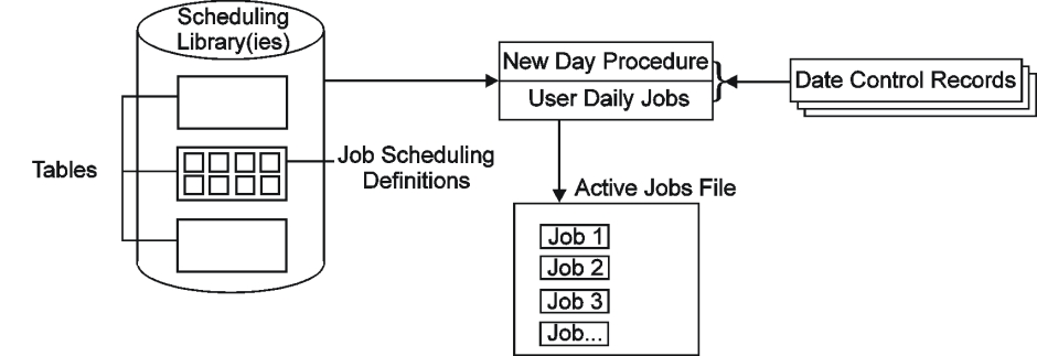
New Day processing generally works as follows:
-
The New Day procedure is performed each day at a predefined time. The New Day procedure:
Schedules User Daily jobs
Schedules maintenance jobs. These jobs call programs that perform cleanup after the previous day’s processing.
-
If a cyclic job is executing at the time the New Day procedure is run, the New Day procedure changes the job to a noncyclic job and handles the job accordingly.
-
If a job that was not submitted on its original scheduling date contains a > specification in its TIME UNTIL field, when the New Day procedure is next run, the procedure deletes the > and TIME FROM specification from the job order, making the job immediately eligible for execution.
-
If History Jobs file processing is enabled, jobs deleted from the Active Jobs file during cleanup can be placed in the History Jobs file.
-
-
User Daily jobs (scheduled by the New Day procedure) select and schedule all other jobs for that day.
-
The following figureshows New Day Procedure and User Daily Jobs:
-
Figure 22 New Day Procedure and User Daily Jobs
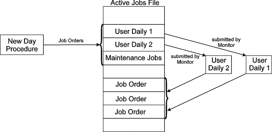
Sample New Day Processing
Control‑M is supplied with samples of several of the above mentioned components.
To effectively implement New Day processing at your site, you must first understand how the sample components operate. Once the operation of the sample components is understood, you can then customize New Day processing based on site requirements. Sample New Day processing components are described in the following section.
Sample Components Provided With Control-M
At time of installation, each site is provided with the components shown in the table.
Table 95 Supplied Sample Control-M Components
|
Component |
Description |
|---|---|
|
New Day Procedure |
A single New Day procedure is provided. Its default name is CTMTDAY (the name can be changed). This procedure must have wide authorization for accessing tables and jobs. |
|
User Daily Jobs |
The following sample User Daily jobs are provided:
These sample User Daily jobs are defined in table MAINDAY in the SCHEDULE Library. These jobs activate User Daily procedure CTMDAILY, which is responsible for ordering the production jobs. It is generally advisable to use these sample User Daily jobs to create separate User Daily jobs according to department (or other functional entity), and according to authorization. For more information, see Job Ordering using New Day Processing. |
|
Maintenance Jobs |
The following maintenance jobs are provided:
These maintenance jobs are defined in table MAINDAY in the SCHEDULE library. For a description of utilities IOALDNRS and IOACLCND, see the INCONTROL for z/OS Utilities Guide. |
|
Table: MAINDAY |
A table called MAINDAY is provided in the SCHEDULE library. This table contains User Daily jobs DAILYSYS and DAILYPRD and maintenance jobs IOACLCND and IOALDNRS. |
|
Date Control Records |
The following Date Control records (members) are supplied in the Control‑M PARM library:
|
|
Called Programs |
The New Day procedure and User Daily jobs call programs that perform various steps of New Day processing (checking the Date Control record, selecting job orders, and so on). For a description of these programs, see Programs Called During New Day Processing. |
How the Sample Components Perform New Day Processing
New Day processing performed with the sample components works as follows:
-
During New Day processing, the New Day procedure accesses its Date Control record, scans table MAINDAY and selects and loads the maintenance jobs and User Daily jobs to the Active Jobs file.
The following figure shows Sample Components of the New Day Procedure:
Figure 23 Sample Components of the New Day Procedure
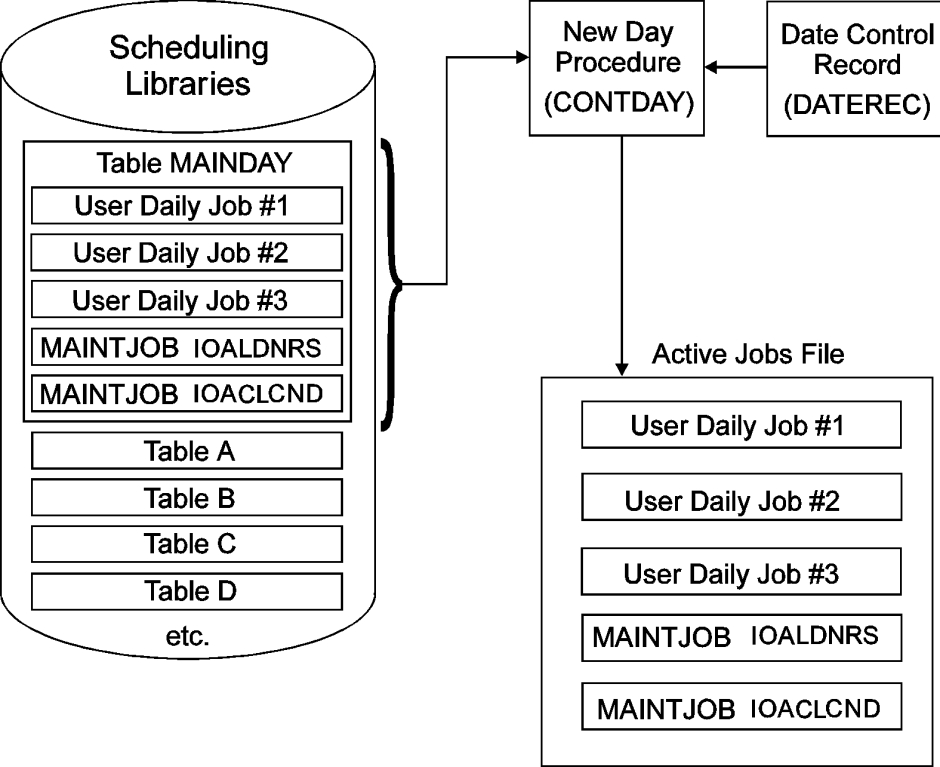
-
The User Daily and maintenance jobs placed in the Active Jobs file are submitted by ControlM according to their runtime scheduling criteria. When a User Daily job is executed, it accesses its own Date Control record, scans the tables defined to it, selects jobs and places the selected job orders in the Active Jobs file. (User Daily jobs can also schedule maintenance jobs as required.)
The following figure shows Jobs Placed in the Active Jobs File:
Figure 24 Jobs Placed in the Active Jobs File
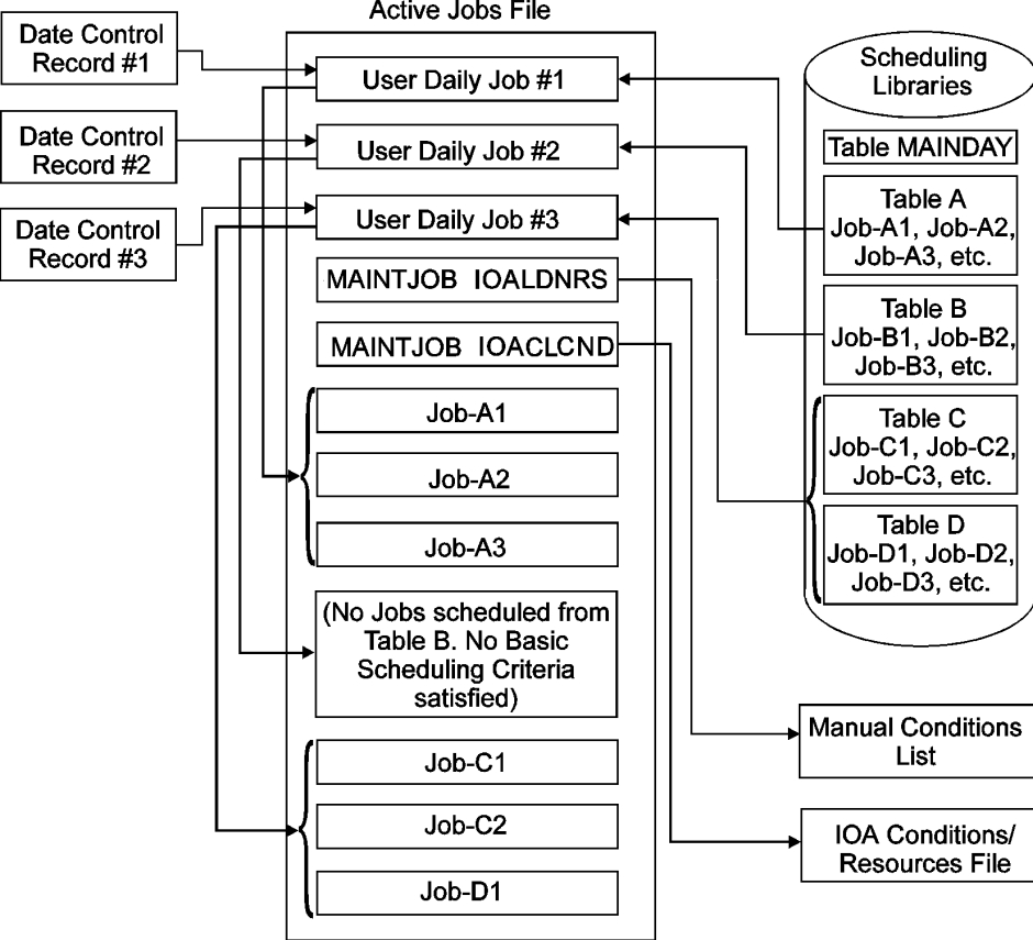
Because the User Daily is a job, its use is not restricted to New Day processing. Although User Daily jobs are normally executed immediately after they are ordered by the New Day procedure, they can be executed at any time defined in their Runtime Scheduling parameters. Furthermore, they can be ordered at any time by any of the methods described in the selected implementation issues chapter in the Control‑M for z/OS User Guide.
Date Control Records and Enhanced Daily Checkpointing
A Date Control record must be defined for each User Daily job. This record is usually defined by the INCONTROL administrator.
The Date Control record for User Daily jobs consists of six fields. At different stages in New Day processing (before or after the execution of specific called programs that perform New Day processing), the current original scheduling date is placed in one of these date fields.
This enables Control‑M to manage the process of job ordering. Furthermore, if New Day processing or a User Daily job is interrupted at any point, the values in these fields can indicate which called program was in use when the interruption occurred.
Enhanced Daily Checkpointing
The Enhanced Daily Checkpoint record is the second record in the Date Control member. It contains fields that store information about the last ordered job: JCL member name, internal sequence number, order ID, and the SMART Table to which the job belongs. (For a description of the format of this record, see Create Date Control Records.) If an interruption occurs during job ordering, the Enhanced Daily Checkpointing record enables precise identification of where job ordering stopped. During recovery, job ordering continues from that point.
BMC cautions against deleting an Enhanced Daily Checkpoint record. If you need to rerun User Daily, and the Checkpoint record has been deleted (or was never present), then all jobs in the table are considered for scheduling, including jobs already scheduled by the interrupted run.
If the job belongs to a SMART Table, the recovery procedure reorders the entire SMART Table. The original SMART Table Entity remains in the Active Jobs file, together with the jobs that were ordered prior to abnormal termination. However, the status of the original SMART Table Entity is set to HELD WAIT SCHEDULE to prevent the jobs in that SMART Table from being submitted. Changing the status of the original SMART Table Entity using the Online facility is blocked.
The same Date Control Record cannot be shared by the Newday procedure, by different User Dailies, and any jobs that invoke the CTMJOB utility. Failure to allocate unique Date Control records for each task that requires one may lead to unpredictable job ordering results.
Before the ordering process starts, the program checks if the checkpoint fields in Record 2 are blank.
If the checkpoint fields are blank, the User Daily job continues normal processing. Before each job is ordered, the fields in Record 2 are updated (overwritten) with information identifying the current job being ordered. Only upon successful completion of the User Daily job is the information in the checkpoint fields erased.
If the checkpoint fields are not blank, the recovery procedure described in Recovery Procedure Using Enhanced Checkpointing is activated.
As part of "Continue on Cards Error" processing, if parameter CNTERCRD in member CTMPARM is set to yes, Control‑M does not stop the ordering process. Control‑M continues even if errors exist. Checkpointing in this case is only relevant for abends or premature termination.
Create Date Control Records
Date Control records are members in the Control‑M PARM library. A different Date Control record must be defined for each User Daily job. It is usually defined only once for each job and from then on it is usually updated by the User Daily job.
The length of the User Daily Date Control record is 80 characters. The format of the dates in the record is mmddyy, ddmmyy or yymmdd, depending on the site standard.
The table shows the format of the Date Control record and indicates when the User Daily adds the original scheduling date values to the fields in the record.
Table 96 Date Control Record Format
|
Column |
Value Added |
Description |
|---|---|---|
|
01–06 |
date1 |
User Daily adds the ODATE before the User Daily procedure is begun. |
|
18–23 |
date2 |
User Daily adds the ODATE before the job ordering process begins for jobs being scheduled based on DATES, DAYS, and/or DCAL parameters. |
|
25–30 |
date3 |
User Daily adds the ODATE after the job ordering process ends for jobs being scheduled based on DATES, DAYS, and/or DCAL parameters. |
|
43–48 |
date4 |
User Daily adds the ODATE before the job ordering process begins for jobs being scheduled based on WDAYS and/or WCAL parameters. |
|
50–55 |
date5 |
User Daily adds the ODATE after the job ordering process ends for jobs being scheduled based on WDAYS and/or WCAL parameters. |
|
60–65 |
Blank (date7) |
In the User Daily Date Control records, these columns are blank. In the New Day procedure Date Control record, these columns are the last formatting date, date7, of the Active Jobs file (used by program CTMFRM). This field prevents formatting from being carried out twice on the same day. When this date is in a record, program CTMCHK recognizes the record as a New Day procedure Date Control record. If there are any problems concerning the date, the program presents the operator with a series of prompts. Misuse of this field by the user frequently leads to the display of error message CTM916W. For more information, see the INCONTROL for z/OS Messages Manual. |
|
67–72 |
date6 |
User Daily adds the ODATE upon completion of all processing. |
A second Date Control record is defined for each User Daily job to implement Enhanced Daily Checkpointing. The column formats of this record are described in the table.
Table 97 Format of the Second Date Control Record (for Enhanced Daily Checkpointing)
|
Column |
Constant or Value Added |
Description |
|---|---|---|
|
01–04 |
JOB= |
Constant. |
|
05–12 |
blank |
In this area, Control‑M stores the MEMNAME value of the last ordered job. |
|
13–23 |
,SERIAL_NO= |
Constant (note the comma before the "S"). |
|
24–28 |
blank |
In this area, Control‑M stores its internal sequence number of the last ordered job. |
|
29–37 |
,ORDERID= |
Constant (note the comma before the "O"). |
|
38–42 |
blank |
In this area, Control‑M stores the order ID of the last ordered job. |
|
43–49 |
,GROUP= |
Constant (note the comma before the "G"). |
|
50–69 |
blank |
In this area, Control‑M stores the group name of the last ordered job. |
When creating this record, the user must
-
specify the indicated constants (for example, JOB) in the appropriate columns
-
leave blank the columns indicated as blank. These columns are filled in by the User Daily during processing
When a SMART Table is ordered, the values in the second Date Control record will be those of the SMART Table Entity, even if a failure occurs in one of the SMART Table’s jobs.
Recovery Procedure Using Enhanced Checkpointing
When a SMART Table is ordered, the values in the second Date Control record will be those of the SMART Table Entity, even if a failure occurs in one of the SMART Table’s jobs.
The program passes over the jobs in the input tables, counting the jobs and comparing the count to the value in the SERIAL_NO field, until the count and serial number match. The matching job is selected.
The program then compares the values in the JOB and GROUP fields to the values belonging to the selected job. If the fields do not match, error message CTMD67S is issued and processing terminates.
-
If the fields match, the program checks the Active Jobs file for a job with an order ID matching the order ID recorded in Record 2. Ifthe match is found, an additional check is performed to verify that the job’s MEMNAME and GROUP values match the checkpoint JOB and GROUP values.
-
If the Active Jobs file already contains the job, the job is not ordered again and the program switches to normal processing starting with the next job.
-
If the Active Jobs file does not contain the job, the job is ordered. The program then switches to normal processing.
If input tables are modified prior to rerunning User Daily jobs (or the New Day procedure), the checkpointed job and internal sequence number might not match. In this case, rerun of the User Daily jobs is terminated and manual intervention is required.
If a problem is encountered in Newday processing related to job ordering, the Newday procedure can be rerun using the ORDERONLY parameter as follows:
S CTMTDAY,NEWDAY=ORDERONLYThe job can be run while the Control-M monitor is active.
Implementing New Day Processing
As indicated above, sample User Daily jobs DAILYSYS and DAILYPRD are supplied with Control‑M in table MAINDAY.
In theory, it is not necessary to use User Daily jobs. It is possible (but not recommended) to place all job scheduling definitions in one or more tables and have them scheduled by the New Day procedure.
It is also possible (and also not recommended) to maintain only the two sample User Daily jobs provided with Control‑M and to order all user jobs through the User Daily DAILYPRD.
The recommended method to automate the production environment using New Day Processing is by
-
defining a different table for each set of related jobs
-
defining a different User Daily job for each department, application or comparable entity
The table described the advantages that such an implementation provides.
Table 98 Advantages of Recommended Method of Automating the Production by Means of New Day Processing
|
Advantage |
Description |
|---|---|
|
Improved performance |
Many User Daily jobs running in parallel can order the full day’s production jobs in significantly less time than can one User Daily that orders all jobs individually. |
|
Ease of administration |
The INCONTROL administrator can make each department responsible for its own User Daily jobs and tables and for controlling its own job ordering. |
|
Increased security |
While maintaining exclusive authorization for the New Day procedure, the INCONTROL administrator can limit each department’s authorization to its own User Daily jobs. |
|
Minimization of problems |
Problems encountered in one User Daily do not necessarily affect the job ordering of other User Daily jobs. |
Differences Between the New Day Procedure and User Daily Jobs
The New Day procedure uses the program list in member PROGDAYM. User Daily jobs use the program list in member PROGUSR.
The New Day procedure uses Date Control record DATEREC (which contains the last Active Jobs file format date in columns 60 through 65). User Daily jobs use Date Control record DATERECU (which contains blanks in columns 60 through 65). Using the wrong Date Control record causes message CTM916W to be generated.
User Daily jobs can be run manually (that is, not initiated by the Control‑M monitor.) However, the Control‑M monitor must initiate the New Day procedure. If an attempt is made to run the New Day procedure manually, problems may be caused by failure of the Control‑M monitor to free the Active Jobs file for use by the New Day procedure.
Implementation Tasks
Perform the following tasks when implementing New Day processing:
-
Decide which User Daily jobs are needed (and for which tables)
-
Customize the New Day procedure.
-
Use the sample JCL to create JCL for each User Daily job
-
Create User Daily job scheduling definitions and customize table MAINDAY
-
Create Date Control and Enhanced Daily Checkpointing records
-
Date Control records cannot be contained in a PDSEtype library.
-
The New Day procedure and its accompanying Date Control record are defined at time of installation. They require no further implementation.
-
-
Ensure subsequent runs of utility IOALDNRS if necessary
Decide Which User Daily Jobs Are Needed (and for Which Tables)
A job scheduling definition is defined for each job and each job scheduling definition is placed within a table. Usually, related job scheduling definitions are grouped into their own table.
Based on the tables defined at your site and the jobs they contain, decide what User Daily jobs you require, and which tables each User Daily job must scan.
Customize the New Day Procedure
The New Day procedure normally performs a cleanup of the AJF, the History AJF, and the IOA Conditions file automatically. The criteria by which jobs and conditions are deleted from the AJF, the History AJF, and the IOA Conditions file are illustrated in the CTMFRM program, described in Programs Called During New Day Processing. The user may change the default actions of CTMFRM by coding SELECT and IGNORE statements in the DAFRMIN DD statements, in both the main step and the CLRHIST step of the CTMTDAY procedure. The DD statements DAFRMIN reference members IGNORE and IGNORHST in the main and CLRHIST steps respectively. For further information, see SELECT and IGNORE Statements. Using these SELECT and IGNORE statements, the user can cause jobs and conditions that normally would be deleted to be retained, and vice versa.
SELECT and IGNORE Statements
SELECT and IGNORE statements identify jobs or conditions that must or must not be deleted.
One or more parameters can be specified in any SELECT or IGNORE statement (in any order). For a description of parameters GROUP, JOBNAME, MEMBER, STATUS, FROM, and TO, see the CTMCAJF utility in the INCONTROL for z/OS Utilities Guide.
A job specified for deletion using a SELECT statement is deleted unconditionally even if the job is currently executing.
Conditions that are not date‑related can be defined with a date reference of STAT, which eliminates the need for including SELECT or IGNORE statements in procedure CTMTDAY.
To suppress the erasure of the next day’s conditions by the New Day procedure, specify the definition
IGNORE COND *When suppressing the function, remember to delete conditions (using utility IOACLCND). If this is not done, jobs in the next year’s schedule is triggered because of today’s conditions.
IGNORE JOBNAME OPER*
IGNORE JOBNAME PROD* STATUS ENDNOTOK
SELECT GROUP   TEST
In this example, no jobs whose names begin with prefix OPER are deleted. Also no jobs whose names begin with prefix PROD that ended NOTOK are deleted. Of the remaining jobs, those belonging to group TEST are deleted. In addition, the default action is also taken. All jobs that ended OK and all jobs whose MAXWAIT interval is exceeded are also deleted even though they are not part of group TEST.
IGNORE STATUS ACTIVE
SELECT JOB OPER*
In this example, jobs whose names begin with prefix OPER are deleted if they are in WAITSCHED, ENDOK or ENDNOTOK status (that is, jobs whose status is ACTIVE are not deleted). In addition, the default action is also taken. All jobs that ended OK and all jobs whose MAXWAIT interval is exceeded are also deleted even though they do not begin with prefix OPER.
AutoEdit variables and functions are supported in the SELECT and IGNORE statements. For more information, see the CTMCAJF utility in the INCONTROL for z/OS Utilities Guide.
Use the Sample JCL to Create JCL for Each User Daily Job
Create the JCL for each User Daily job by selecting one of the alternative methods of identifying tables (below) and customizing the JCL accordingly.
Table 99 Methods for Identifying Tables
|
Method |
Description |
|---|---|
|
Method 1 |
Copy
This method requires that the user specify the name of a table and library directly in the JCL. Copy
|
|
Method 2 |
Copy
This method requires that the user specify a parm_library and member containing ORDER requests that identify scheduling libraries, tables, and jobs to schedule—and/or in-stream ORDER requests—following //DAJOB DD * Method 2 provides the following advantages over Method 1 Changes required can be made to the member in the parm_library without changing the JCL of the User Daily job. Individual jobs can be specified. An entire library can be ordered with one order statement in the format: ORDER DSN=AAA.BBB.CCC,MEMBER=* When using Method 2, specify at least one ORDER statement and, optionally, SELECT or IGNORE statements. The Date Control record is referenced by DD statement DACHK. For the syntax, parameter descriptions and functionality of the ORDER, SELECT and IGNORE statements, see the CTMJOB utility in the INCONTROL for z/OS Utilities Guide. |
Create User Daily Job Scheduling Definitions and Customize Table MAINDAY
The supplied sample User Daily jobs, DAILYPRD and DAILYSYS, scan the tables referenced by DD statement DAJOB. However, different authorization is granted to each of these User Daily jobs.
Use these sample User Daily jobs to create a User Daily job for each department in table MAINDAY. Assign the authorizations accordingly. Each User Daily job must scan a different set of tables than the other User Daily jobs.
It is common in many sites for the INCONTROL administrator to create a customized User Daily job for each department and then turn the table over to the control of the department. The department can then modify the table (and job scheduling definitions) as necessary.
Although User Daily jobs can execute immediately after the jobs have been placed in the Active Jobs file, a site may choose to delay execution of a User Daily. To delay the submission of a User Daily, define the User Daily’s runtime scheduling criteria accordingly.
If groups of User Daily jobs are executed at different times, rerun IOALDNRS after running each group of User Daily jobs.
Add additional maintenance jobs table MAINDAY as necessary.
Ensure Subsequent Runs of Utility IOALDNRS if Necessary
If all User Daily jobs are scheduled to run in parallel, utility IOALDNRS only needs to run once, after the User Daily jobs have finished execution. However, if User Daily jobs are executed at various times during the day, utility IOALDNRS must be run after each group of User Daily jobs is executed. This can be ensured by having each group of User Daily jobs set the appropriate prerequisite conditions to ensure the execution of IOALDNRS.
Programs Called During New Day Processing
The most important programs in New Day processing are CTMILZ and CTMILU.
-
The New Day procedure executes program CTMILZ.
-
Each User Daily calls procedure CTMDAILY, which executes program CTMILU.
Programs CTMILZ and CTMILU both execute other programs that implement New Day processing. The programs called by CTMILZ and CTMILU are listed in the table below. Both CTMILZ and CTMILU read the member referenced by DD statement DAPROG and activate the programs listed in the member.
The following table describes the format for each record in the program list:
Table 100 Column Format for Program List Records
|
Column |
Description |
|---|---|
|
01–08 |
Program name |
|
10–11 |
Maximum return code allowable in the preceding program If a higher return code is encountered in the preceding program, the current program is not executed. |
|
13–72 |
Program arguments |
The following table shows the programs called by program CTMILZ (the New Day procedure) and by program CTMILU (User Daily jobs).
Table 101 Programs Called by New Day Procedure and User Daily Jobs
|
Program |
Purpose |
|---|---|
|
CTMCHK |
(called by CTMILZ and by CTMILU) Checks the current date and its relation to the Date Control record (described in the topic Use of the Date Control Record by User Daily Jobs. When called by CTMILZ, the program always prompts the operator to verify that Control‑M is activated on the correct date. When called by CTMILU, the program prompts the operator to verify that Control‑M is activated on the correct date only if the value CONFIRM is specified as the program argument (anywhere within columns 13 through 72). |
|
CTMFRM |
(called by CTMILZ) Reformats the Control‑M Active Jobs file, Control-M History Jobs file, and the IOA Conditions file: Control‑M Active Jobs File By default (that is, if no SELECT or IGNORE statements are specified), the following jobs are erased from the Active Jobs file and the file is compressed:
Control-M History Jobs File Compresses the Control‑M History Jobs file (if activated) by removing jobs whose retention criteria (RETENTION – # OF DAYS or GENERATIONS TO KEEP) have been exceeded. IOA Conditions File This program erases all prerequisite conditions whose data is the same as the new Control‑M working date (that is, this program erases all prerequisite conditions of the coming execution date).
At start of execution, this program creates a backup copy of the Active Jobs file (BKP file) for recovery purposes. |
|
CTMJOB |
(called by CTMILZ and by CTMILU) Places job orders in the Active Jobs file according to the date in the Date Control record and the data in the tables supplied. |
|
CTMPDA |
(called by CTMILZ and by CTMILU) Marks the end of the Daily run. |
If History Jobs file processing is enabled, program CTMFRM is run again using program CTMILZ, this time against the History Jobs file, as shown in the above table.
If Control-M/Restart is installed or the History feature is activated, steps DELARCH and CLRHIST are run after the conclusion of program CTMILZ, as shown in the following table:
Table 102 Additional Steps Executed by New Day Procedure if Control-M/Restart Is Installed or the History feature is activated
|
Program |
Purpose |
|---|---|
|
CTMDAS |
Deletes archived SYSDATA (CDAM files) of jobs that were deleted from the Active Jobs file by program CTMFRM according to the following logic:
|
|
CTMHSC |
Deletes expired jobs from the History Jobs file. |
The following table shows the additional step that is run to copy the Control-M Journaling file:
Table 103 Additional Step Executed by New Day Procedure if the Control-M Journaling feature Is Activated
|
Program |
Purpose |
|---|---|
|
IKJEFT01 |
Copies the Control-M Journaling file to a backup file (via CLIST CTMCJNL). |
Use of the Date Control Record by User Daily Jobs
The workflow of User Daily jobs is dependent on the Date Control record. The main steps of a User Daily job are
-
checking the last running date of the User Daily job (using internal program CTMCHK)
The first date in the Date Control record (columns 1 through 6) is compared to the current working date (at the time of the run).
-
If they match, the User Daily job has already run today. Anappropriate message is issued and the condition code is set to 0008.
-
If the current working date is earlier than the first date of the Date Control record, a User Daily job run has been attempted before its time. TheUser Daily job stops executing and notifies the user accordingly.
-
If the current working date is later than the first date of the Date Control record (the normal situation), the first date of the Date Control record (columns 1 through 6) is updated to the current working date. This date is then used as the current scheduling date.
If the User Daily job did not run for more than one day, a warning message is issued, and the User Daily job tries to schedule the jobs for all of the days that have passed since the last scheduling date (according to the production parameters). In such a case, you may want to run the User Daily job from a previous day, as described in Running a User Daily from a Previous Working Day.
However, if the program list record for program CTMCHK contains the program argument CONFIRM, the User Daily issues a series of WTOR messages. For information about operator responses to these messages, see New Day Procedure Flow.
-
-
placing job orders in the Active Jobs file according to the current scheduling date and the last running date (using utility CTMJOB)
There are two methods for placing job orders in the Active Jobs file using utility CTMJOB. For a description of both methods, see Use the Sample JCL to Create JCL for Each User Daily Job.
For each job, the program checks whether the job must be scheduled on one or all of the days that have passed since the last original scheduling date (date3 or date5) until the working date in the record (date1). If the job must be scheduled, a job order is placed in the Active Jobs file.
When the program finishes processing the user tables, the finish indicator dates (date3 and date5) are updated to the working date (date1) calculated by program CTMCHK.
Before program CTMJOB starts operating, it compares date2 with date3 (and date4 with date5). If they do not match, a previous run of program CTMJOB of the same User Daily job has probably abended. The user is notified and the program terminates. To correct the error, adjust the date values in the user Date Control record (using a standard editor).
When manually modifying the Date Control record, make sure that jobs are not scheduled to run twice on the same day.
indicating that the User Daily job has ended (using program CTMPDA)
Program CTMPDA updates the finish indicator date (date6) by setting it to the value of the running date (date1). This indicates that the User Daily job finished successfully.
-
rerunning the User Daily job after a failure
For further information, see Date Control Records and Enhanced Daily Checkpointing.
New Day Procedure Flow
Once a day, at a time set by the INCONTROL administrator, the Control‑M monitor begins New Day processing by going into a suspended state and issuing the following messages (the first is a highlighted, unrollable message):
CTM113I Control‑M MONITOR monitor NEW DAY PROCESSING STARTED
CTML00I Control‑M MONITOR monitor PROCESSING SUSPENDED
CTML07W Control‑M MONITOR monitor WAITING FOR NEWDAY PROCEDURE
Shortly after that last message is issued, started task CTMTDAY (the New Day procedure) is automatically activated.
-
If CTMTDAY finishes executing without any problems, the following messages are issued, and the suspended Control‑M monitor resumes normal processing:
CopyCTML01I Control‑M MONITOR monitor PROCESSING RESUMED
CTML02I Control‑M MONITOR monitor NEW DAY PROCESSING COMPLETE -
If a problem occurs during the formatting step (CTMFRM) of CTMTDAY processing, the ControlM monitor prompts the operator for an appropriate response using the following messages:
CopyCTML05W NEW DAY PROCESSING ERROR DETECTED
CTML06W REPLY "R" FOR RESUME OR "E" FOR END
The operator should try to correct the problem and rerun the CTMTDAY procedure as described below. Once the CTMTDAY procedure runs successfully, the operator should reply R to message CTML06W, which enables the
Control-M monitor to resume normal processing. Terminating execution of the Control-M monitor (option E) should only be requested if the problem cannot be corrected.
Procedure CTMTDAY can be rerun—while the Control-M monitor is suspended for Newday processing—in one of the modes described in the following table.
Table 104 CTMTDAY modes with Control-M monitor suspended
|
Command |
Description |
|---|---|
|
Copy
|
AJF formatting and job ordering are performed as in normal Newday processing. The formatting step includes deletion of the current Control-M working day conditions from the IOA Conditions file. |
|
Copy
|
Performs job ordering only and not AJF formatting. If date is not specified, the current ODATE is used. Otherwise, date determines the ODATE. |
|
Copy
|
Performs AJF formatting only (equivalent to the COMPRESS command of utility CTMCAJF). Does not delete conditions for the current working day. |
If the CTMTDAY problem is related to a Table problem, setting parameter CNTERCRD to Y in member CTMPARM can avoid such CTMTDAY failures. If this parameter is set to Y, the ordering process bypasses scheduling errors within a job, and skips to the next job. If the error is in a SMART Table Entity or in a job belonging to a SMART Table, processing skips the entire table and continues with the next job or table. If the CNTERCRD parameter is set to N, it may be necessary to rerun the job ordering process of the CTMTDAY procedure, as follows:
S CTMTDAY,NEWDAY=ORDERONLY-
During New Day processing, CTMTDAY checks the system date and time against what it expects to find in the ControlM control files. If they do not match, the operator is prompted with the following messages:
CopyCTM426W CTMTDAY "DAILY" DID NOT RUN FOR nnnnnn DAYS
CTM43CI CONTENTS OF DATE Control RECORD:
CTM437I date-1 date-2 date-3 date-4 date-5 date-6 date-7
CTM439W REPLY 'C' TO CONTINUE, 'U' TO UPDATE DATEREC TO
CURRENT DAY EXECUTION, OR 'E' TO ENDRespond using one of the following options:
-
C—all conditions in the IOA conditions file whose date corresponds to the intermittent days will be deleted. If RETRO is enabled in the scheduling definition, jobs for all intermittent days will also be ordered.
-
U—updates the Date Control Record to the current system date and continues execution. (Only jobs scheduled for the current working day will be ordered.)
-
-
If the computer has not been working for a few days (for example, a hardware failure or holiday), enter one of the following:
-
If the computer was IPLed with the wrong date, enter E, check and correct the date on the computer, and then restart procedure CTMTDAY.
-
If the date on the computer is correct and was working the previous day, contact the INCONTROL administrator to check the cause of the problem.
-
If the Control‑M monitor has been down for more than 28 days, the previous working date (the current working date minus 1) must be manually specified as date values 1 through 6.
Running a User Daily from a Previous Working Day
At times, you might need to run or rerun a User Daily from a previous working day. To semi-automate this process, perform the following steps:
-
Define a member PROGNCHK in the CTM PARM library. This member must contain at least the following 2 lines:
CopyCTMJOB 04
CTMPDA 04These lines may be copied from the second and third lines of member PROGUSR in the same library.
-
Copy member DATERECU in the CTM PARM library to a new member DATERECR. In this new member, specify the required scheduling date for the particular run as the first date on the statement, and the remaining dates as an earlier date.
For example, in the following member, the scheduling date is October 12, 2020:
Copy121020 111020 111020 111020 111020 111020 -
Run the CTMDAILY User Daily procedure with the DATEREC and PROGLST parameters as set below:
Copy//PRD EXEC CTMDAILY,DATEREC=DATERECR,PROGLST=PROGNCHK -
When ordering the User Daily job via Control-M, specify the required scheduling date as the ODATE of the job.
This ensures that job order messages JOB528I in the User Daily output contain the desired ODATE.
Managing User Daily Jobs from Control-M/EM
The content of User Daily jobs executing in an MVS datacenter can also be managed from the Control-M/Enterprise Manager, which runs on a Windows platform. Special User Daily jobs must be defined for this purpose. They provide a means by which the following functions can be performed from Control-M/EM:
-
Add a table residing in a specific library to an existing user daily job.
-
Change the location of a table by moving it from one user daily job to another.
-
Delete a table from a user daily job.
For more information, see User Daily in the documentation for Control-M for Distributed Systems.
By default, the EMUSDLY parameter, in the CTMPARM member, is set to Y. This enables you to use the CTMEMUDL procedure, which runs the CTMUDR program, to process the Special User Daily Jobs.
The User Daily data that is uploaded from Control-M/EM is stored in one of the following locations:
-
Versions earlier than 9.0.21.100: In IOA Global variables
Usage of this storage location requires global variable database structures to be active, as well as Control-M Event Manager or Control-O.
It also limits the efficiency of using Control-M/EM dailies. Therefore, limit the use of Control-M/EM dailies to no more than a few ad-hoc folders. For most of your folders, use the standard mainframe dailies, controlled by CTMJOB.
-
Version 9.0.21.100 or later: In member UDLINDEX
UDLINDEX is located in CTMPARM (by default), or in some other non-default member that you specify in DD card DAUDR.
To use this storage location, you must first activate it and migrate existing User Daily data into it (for example, if you have upgraded from an earlier product version). You activate the UDLINDEX member using a one-time CTMEMUDL procedure, as described below.
In addition to the Special User Daily jobs, which are processed using the CTMEMUDL procedure, those tables that are specified from Control‑M/EM to run automatically (and are therefore marked as SYSTEM tables) are also processed as part of the New Day procedure. It is the responsibility of the Control-M Administrator to schedule the execution of the other User Daily jobs. For more information, see the INCONTROL for z/OS Installation Guide.
To activate the storage of User Daily data in member UDLINDEX (in product version 9.0.21.100 or later), run the following CTMEMUDL procedure:
EXEC CTMEMUDL,EMDAILY='$$CONVERT'Use the following JCL template to routinely run the CTMEMUDL procedure:
EXEC CTMEMUDL,EMDAILY=userdailynameBefore issuing the command replace userdailyname with a 10 character name referring to a set of tables to be ordered in the AJF.
The CTMEMUDL procedure generates ORDER statements for all tables that belong to the Control‑M/EM User Daily job, userdailyname. The ORDER statements are subsequently processed by the CTMJOB utility, which places the jobs in the AJF.
To view the contents of a specific Control-M/EM User Daily job, use the LIST option, as shown in the following command:
EXEC CTMEMUDL,EMDAILY='userdailyname,LIST'To view the contents of all Control‑M/EM User Daily jobs, use the '*,LIST' option, as shown in the following command:
EXEC CTMEMUDL,EMDAILY='*,LIST'Job Ordering and Submission Considerations
Library Compression
If a job is ordered or submitted while certain libraries are being compressed, the member may not be found or the wrong job may be submitted. To avoid this problem, compress a library only when Control‑M is down, or no jobs contained in or referencing the library are being submitted or ordered. The following libraries are relevant to this issue:
-
the JCL library
-
ControlM job scheduling libraries
-
IOA calendar libraries
JCL Parameter MSGLEVEL
Output of a Control‑M job is written to the Control‑M SYSDATA only if a MSGLEVEL of (1,1) is specified. If Optional Wish WM0735 is applied at your site and no MSGLEVEL, or a MSGLEVEL other than (1,1) is specified, Control‑M automatically changes the MSGLEVEL to (1,1).
Comment Lines Added During Job Submission
Control‑M adds the following comment lines to the JCL output of each job that is executed using Control‑M:
//*-- SUBMITTED BY Control-M (FROM lib)    ODATE=odate
//*-- SCHEDULE schedlib(sched-table)
//*-- SCHEDULED DUE TO RBC: rbc-name
//*-- JCL     jcllib(jclmembr)
//*--  Control-M JOB IDENTIFICATION: ORDER ID=order-id RUN NO.=run-number
where
-
lib is either MEMLIB or OVERLIB
-
odate is the Control-M order date
-
schedlib is the scheduling library from which the job was ordered
-
sched-table is the table from which the job was ordered
-
rbc-name is either blank or (for jobs in SMART Tables) the schedule RBC that caused the job to be ordered
-
jcllib is the JCL library from which the job was submitted
-
jclmembr is the JCL member from which the job was submitted
-
order-id is the Control-M order id assigned to the job
-
run-number is the number of times the job has run or rerun
If Control-M is upgraded from a non-supported version, the values for the scheduling library, table, JCL library, and JCL member may appear as UNKNOWN for jobs ordered before the upgrade.
The value in the SCHED comment line is also indicated as UNKNOWN when you perform an AutoEdit simulation using the JCL library mode.
Volume Defragmentation and Compaction
If a job is ordered or submitted while DASD volumes containing IOA or Control‑M libraries are being defragmented or compacted by DASD management products, the library may be in use, not found or not cataloged—causing the job not to be submitted. To avoid this problem, defragment or compact volumes containing IOA or Control‑M libraries only when Control‑M is down, or no jobs contained in or referencing these libraries are being ordered/submitted.
The following libraries are relevant to this issue:
-
The JCL library
-
ControlM job scheduling libraries
-
IOA calendar libraries
At sites where running the above type of DASD housekeeping while Control‑M is active is unavoidable, carefully set the following parameters (defined in member CTMPARM of the IOA PARM library) to alleviate the problem:
-
INUSE#RT
-
INUSE#WI
Job Order Interface—Defining Job Lists for Each User
When an end user orders jobs using the End User Job Order Interface utility, the list of jobs that end user can order is displayed. For more information, see the online facilities chapter in the Control‑M for z/OS User Guide.
When using the End User Job Order interface, a user is permitted to order jobs in tables determined by the INCONTROL administrator. Multiple users can utilize the same table. The INCONTROL administrator must ensure that the tables do not contain jobs with duplicate jobnames.
To identify which table each user can utilize, the INCONTROL administrator defines a special control member. This control member lists users and the available table for each user.
The control member must be defined in a PDS with LRECL=80, RECFM=F, or FB. The default location is the @@USRTBL member in the Control‑M SCHEDULE library, but these values are parameters to CLIST and CTMJBINT, and can be modified according to site requirements. This control member may contain multiple lines for each user ID or mask, and is maintained by the INCONTROL administrator.
The following table shows how each line is formatted:
Table 105 Format of Lines in the Control Member
|
Columns |
Description |
|---|---|
|
Cols 1–8 |
TSO user ID or mask. See TSO User ID Masking. |
|
Col 9 |
Blank. |
|
Cols 10–17 |
Table name in the scheduling table library. |
|
Cols 18–19 |
Blank. |
|
Cols 20–63 |
Name of the scheduling table library (required only if different from the library where the control member is located). If this entry is non‑blank, it must contain a fully qualified dataset name including the high-level qualifier and must not be enclosed in quotes. |
|
Col 64 |
Blank. |
|
Cols 65-72 |
Jobname prefix. If this field is blank, the user can order any job in the table. |
|
Col 73 |
Indicates whether the jobname in column 65 is to be treated as a full jobname or a generic jobname prefix. An X in column 73 prevents the jobname from being treated as a generic prefix name. |
The @@USRTBL member must not contain TSO line numbers in columns 73-80.
Any line containing an asterisk in the first column is treated as a comment and is not processed.
TSO User ID Masking
An asterisk (*) specified as the final non‑blank character represents any number of characters (including no characters). For example, if columns 1 through 8 on the control card contain the value ABC*
-
user ID ABC or ABCDEF result in a match
-
user ID AB or XABC do not result in a match
Security Considerations
All security parameters must be backed up in such a way that they can be installed in the backup computer as a whole, not as a special "patch" installation.
Pay special attention to the following points:
-
The correct implementation of the security authorizations needed by the ControlM monitor (that is, defining the ControlM monitor and its special authorization to the security package used in the backup computer).
-
All security parameters and definitions must be backed up and copied to the backup computer.
-
Third-party vendor exits relating to ControlM (for example, RACF exit for R1.7 and R1.8—see the RACF Security Guide) must be copied, installed and checked in the backup computer, thus enabling a quick and correct implementation if the need arises.
-
ControlM security exits, if used, must be checked and passed as a part of the disaster recovery plan.
Executing the M6 utility as a REXX EXEC
When executed as a REXX executable, the M6 utility contains additional options. These allow additional arguments to be passed for enhanced processing.
TSO CTMJBINT [arg1] [arg2] [arg3]
|
Parameter |
Definition |
|---|---|
|
arg1 |
Specifies whether a debug trace of the REXX should be produced. Such traces need to be produced only when requested by BMC. Otherwise, this parameter should be specified as X=X. |
|
arg2 |
Specifies whether the Job Scheduling Definition should be forced or ordered by specifying YES or NO. |
|
arg3 |
Specifies an alternate control member that identifies the table the user should utilize. |
If the default value of the parameter is satisfactory, you do not need to add additional arguments. However, if arg3 is specified, you must also specify arg1 and arg2. Similarly, if arg2 is specified, arg1 is required.
Order the job scheduling definitions selected from the table specified by the @ALTUSR control member:
TSO CTMJBINT X=X NO @ALTUSRForce the job scheduling definitions selected from the table specified by the default control member:
TSO CTMJBINT X=X YESProduce a debug trace when requested by BMC:
TSO CTMJBINT DEBUG ("DEBUG")Activation of Started Tasks
Control‑M can activate started tasks as well as jobs. For a description of the JES2/JES3 definitions that are required to support started tasks, see the Control‑M chapter in the INCONTROL for z/OS Installation Guide: Installing.
When working in a multi‑CPU environment, Control‑M can also activate started tasks in CPUs other than the one in which the Control‑M monitor is active.
Under JES2, the Control‑M monitor activates started tasks in other CPUs by using command $Mm, where m is the appropriate system ID. This system ID is defined in the JES2 initialization parameter one of the following ways:
MASDEF SID(n)=cccc
Sn SID=cccc (under older versions)
For more details, see the IBM manual JES2 Initialization and Tuning Reference.
JES2 fails a $Mm command if m is the ID of the system ID in which the Control‑M monitor itself is working. Therefore, when Control‑M is ordered to activate a started task in a specific system, it determines whether a $Mm command or a regular MVS START command must be issued. To ensure that this check is performed correctly, all the CPUs in your computer complex must be defined. For specific definition information see Step 6.3 – Specify IOA CPUs, in the Customized installation section of the INCONTROL for z/OS Installation Guide: Installing.
Under JES3, the Control‑M monitor activates started tasks in other CPUs by issuing a "*T cccc" JES3 command, where "*" is the JES3 command prefix and cccc is the required system ID. This system ID is defined in the JES3 initialization deck (INISHDECK) as follows:
MAINPROC,NAME=cccc,SYSTEM=JES3,...For MVS, JES3 command RO cccc is issued.
Managing the Control-M Application Server (CTMAS)
The Control-M Application Server (CTMAS) communicates with the Control‑M/Enterprise Manager, a software product that runs on a UNIX or Windows platform and provides centralized control of the job scheduling environment for the enterprise. The purpose of the Control-M Application Server is to interface between the Control-M/EM and the Control-M environment on the z/OS platform.
Functions of the Control-M Application Server
The primary functions of the Control-M Application Server are:
-
to synchronize the data in the Control-M active environment on the z/OS platform with that on the Control-M/EM server.
-
to process user requests received from the Control-M/EM environment and acting on the z/OS data center. Such requests include uploading tables and calendars, ordering jobs, and monitoring job execution.
-
to process system requests received from the Control-M/EM environment and acting on the z/OS data center. Such requests include receiving and sending global conditions.
Activating the Control-M Application Server
The Control-M Application Server is activated by starting the IOAGATE started task that starts the corresponding CTMAS task. To do so, issue the following operator command:
S IOAGATEDeactivating the Control-M Application Server
The Control-M Application Server is deactivated by stopping the IOAGATE started task that starts the corresponding CTMAS task. To do so, issue the following operator command:
P IOAGATECTMAS Operator Commands
To stop communication between CTMAS and Control-M/EM, issue the following command:
F CTMAS.CTMAS001,STOPLINKTo establish communication between CTMAS and Control-M/EM, issue the following command:
F CTMAS.CTMAS001,STARTLINKTo enable or disable trace entries pertaining to CTMAS, issue the following command with the appropriate trace parameters:
F CTMAS.CTMAS001,TRACE=(…)For details about usage and parameters, see Internal Trace facility.
To print out a summary of storage memory allocations to the DAPRENV statement, issue the following command:
F CTMAS.CTMAS001,LISTVSUMTo print out a detailed map of storage memory allocations to the DAPRENV statement, issue the following command:
F CTMAS.CTMAS001,LISTVDETThe Download Process
The download process consists of transferring a new image of the Control-M repository to the Control-M/EM server. Data transferred consists of the following files:
-
the Control-M Active Jobs File
-
the Control-M Resource files
-
the IOA Conditions file
Download always takes place following New Day processing by the Control-M monitor. Download also occurs whenever communication with the Control‑M/EM gateway is reestablished.
Message CTWH06I in the CTMAS job log signals the completion of the download process. It indicates the confirmation by Control-M/EM that the download was successful.
Download Job Filtering
Sometimes it is necessary to manually prevent a specific job from being downloaded to Control-M/EM, because the job definition causes problems on the Control‑M/EM database or because it caused CTMAS to abend during the previous download. In the latter case, the CTMPARM parameter DWNLDERR can be set to value EMX (the default value) in order to automatically exclude the job from the next download when CTMAS is restarted.
Alternatively, the LOG value can be specified for the DWNLDERR parameter, in which case a message is written to the IOA log indicating which job was being processed at the time of the abend, but the job is not excluded from the next download.
In order to manually prevent a specific job from being downloaded to Control‑M/EM, the EMDOWNLD service of the CTMAPI utility can be used to perform such an action. EMDOWNLD provides the following functions:
-
EXCLUDE - Exclude job specified from being downloaded to ControlM/EM
-
ACCEPT - No longer exclude job specified from being downloaded to ControlM/EM
-
EXCLUDE LIST - List all jobs currently excluded from download to ControlM/EM
-
ACCEPT ALL - Include all currently excluded jobs in the next download to Control-M/EM
For information on the format of commands using the CTMAPI utility, please see the Control-M for z/OS User Manual.
Prevent download of job: Orderid 000DB
//S1 EXEC PGM=CTMAPI,PARM='EMDOWNLD EXCLUDE OID=000DB’Allow download of job: Member name BR14
//S1 EXEC PGM=CTMAPI,PARM='EMDOWNLD ACCEPT MEMBER=BR14’Managing the API Gateway
The Control-M API Gateway Application Servers (CTMAASx) are controlled by the Control-M API Gateway and are responsible for sending API REST requests to the relevant services.
These Application Servers are started and stopped on demand by the API Gateway according to the load of user requests directed from the EM. For example, when only sporadic Job Log requests need to be served, two Application Servers are started. However, if the load changes and more frequent requests are encountered ( for example, requests initiated by the Control-M Workload Archive), up to four servers are started.
Activating the Control-M API Gateway
The Control-M API Gateway is normally activated by CTMCAS, and the Control-M API Gateway then activates the Application Servers (CTMAASx). To manually activate the API Gateway, you can issue the following operator command:
S CTMAPIGDeactivating the Control-M API Gateway
The Control-M API Gateway Application Servers are deactivated by stopping the Control-M API Gateway started task. To do so, issue the following operator command:
P CTMAPIGCTMAASx Operator Commands
To enable or disable trace entries pertaining to CTMAASx (the Control-M API Gateway Application Servers, where x is the Application Server number), issue the following command with the appropriate trace parameters:
F CTMAASx,TRACE=(…)For details about usage and parameters, see Internal Trace facility.
To print out a summary of storage memory allocations to the DAPRENV statement, issue the following command:
F CTMAASx,LISTVSUMTo print out a detailed map of storage memory allocations to the DAPRENV statement, issue the following command:
F CTMAASx,LISTVDETCTMAPIG Operator Command
To display the current status of the active and idle mailboxes, which are used by the Control-M API Gateway (CTMAPIG) to communicate with its Application Servers, issue the following command:
F CTMAPIG,APPL=HEALTHControlling the API Gateway Trace
To control the API Gateway trace, adjust the logging levels in member CTMAPARM in the ilprefa.PARM library, as directed by BMC Support. For example:
--logging.level.root=INFO \
--logging.level.com.bmc.ctmsServices.ZosApiGtw=DEBUG \
--logging.level.com.bmc.ctmsServices.ZosApiGtwConnectors=TRACE
Managing the CMEM Facility
The Control‑M Event manager (CMEM) handles events occurring outside the control of the Control‑M monitor. CMEM consists of a monitor that uses the IOA subsystem to perform predefined actions in response to system events (for example, arrival of a specified job on the job spool).
CMEM and Control-O
If Control‑O is installed, the Control‑O monitor assumes control of the CMEM facility and performs CMEM functions using its own monitor and subsystem facilities, rendering this description of CMEM irrelevant. Control‑O and the IOA subsystem use the same subsystem name. For information about managing the CMEM facility when Control‑O is installed, see Control-O.
Before starting Control‑O, CMEM must be shut down.
When Control‑O is shut down, the CMEM facility is also shut down. To restart Control‑O CMEM support after Control‑O has been shut down, issue the following operator command (do this only in an emergency situation):
S CONTROLO,TYPE=CTOCMEMActivating the CMEM Facility
It is recommended that CMEM be active in every computer in the data center (not just in the computer where the Control‑M monitor is working). However, it is possible that in your data center CMEM does not operate in all the computers. (This option is controlled by the Control‑M installation parameters.)
The CMEM monitor must operate 24 hours a day. The usual way to ensure this is to automatically initialize the CMEM monitor during the IPL process. For more information, see the Control‑M chapter in the INCONTROL for z/OS Installation Guide: Installing. To activate the CMEM Subsystem manually, use the operator command
S CTMCMEMThe same operator command can be used to activate the CMEM monitor manually.
Deactivating the CMEM Facility
Under normal circumstances, the CMEM monitor is not shut down. However, CMEM shutdown may be necessary for the following reasons:
-
to resolve a problem that cannot otherwise be resolved
-
In this case, the monitor must be immediately restored to minimize the impact of the shutdown on the work environment.
-
to clean up (erase) all loaded CMEM tables from memory, or stop all CMEM functionality (for example,for a system shutdown)
To stop and immediately restart the CMEM facility, replace the active CMEM monitor by starting a new CMEM monitor. For more information, see Replacing an Active CMEM Monitor.
When the monitor replacement method is not applicable, and a complete shutdown is required, issue one of the following operator commands:
F CTMCMEM,STOP
P CTMCMEM
CMEM shuts down after a few minutes.
CMEM rules are never triggered for dataset events and step termination events caused by jobs that start when CMEM is down.
Replacing an Active CMEM Monitor
If a CMEM monitor is currently active, and a new CMEM monitor is started (using operator command S CTMCMEM), the current CMEM monitor passes execution control to the new CMEM monitor and then shuts down. It is not necessary to reload the rule tables. They are passed from the current monitor to the new one. Therefore, to stop and immediately restart the CMEM monitor with minimum interference to ongoing work, issue the following operator command:
S CTMCMEMReplacing the Active CMEM Executor Modules
When the active CMEM monitor is replaced, most CMEM modules are automatically reloaded. If maintenance is supplied for CMEM executors modules or their messages, a reload command can be used to replace the modules without stopping CMEM.
The following modules can be refreshed:
-
CTOWTO, a CMEM executor module
-
CTOAIDT, a CMEM executor module
-
messages that are used by the above modules
To replace module CTOWTO, use the operator command
F CTMCMEM,RELOAD=CTOWTOTo replace the messages used by CTOWTO, use the operator command
F CTMCMEM,RELOAD=MESSAGESReplacing the Active UNIX for z/OS (OpenEdition) Interface Module (CTOAODT)
When the active CMEM Monitor is replaced, most CMEM modules are automatically reloaded. However, the CTOAODT module must be separately reloaded if maintenance is supplied for the Unix for OS/390 (OpenEdition) interface module.
CTOAODT is shared among different IOA environments that are active in the system. Therefore, to replace the module, the current CTOAODT copy must be deactivated in all IOA environments on the system before a new copy can be loaded.
Deactivating the Current Copy of CTOAODT
To deactivate the current CTOAODT copy in all IOA environments on the system, do the following:
-
Stop UNIX for z/OS (OpenEdition) support by issuing the following operator command for the CMEM Monitor of every IOA environment on the system:
CopyF monitor,STOPOE -
Alternatively, stop the appropriate monitor.
Wait for the following message to appear:
CopyCTO792I OPENEDITION INTERFACE MODULE REMOVED -
After the CTO7921 message has been displayed, UNIX for z/OS (OpenEdition) has been stopped, and the new copy of CTOADT can be loaded.
Loading the New Copy of CTOAODT
The procedure for loading the new CTOAODT copy in all IOA environments on the system is shown in the following steps:
-
Load the new module with the following operator command for the CMEM Monitor of the environment in which the PTF was applied:
CopyF CMEM,STARTOE -
Verify that the following message appears:
CopyCTO781I OPENEDITION INTERFACE MODULE SUCCESSFULLY LOADED -
Restore the OpenEdition support in the rest of the IOA environments where it was previously stopped, by running the following operator command for the CMEM Monitor of each one of them:
CopyF monitor,STARTOE -
Alternatively, restart the appropriate monitor if it was stopped.
Automatic Restart Management (ARM) and CMEM
The CMEM monitor should not be defined for Automatic Restart Management (ARM) because
-
CMEM has its own recovery process
-
since CMEM is active on each system, there is no need to move it to another system when the original system becomes inactive.
Loading Rules
CMEM loads rules in E/CSA. Rules are loaded during CMEM startup under the following conditions:
-
it is the first time CMEM is started up
-
the operator issues the CMEM modify command C
-
a user forces the CMEM rules table from the Tables list of the ControlM Event Manager Rule Definition screen (ScreenC)
During the load process, the monitor performs logical checks to verify the correctness of the rule.
In case of an error, the rule is rejected and an error message prints in the IOA Log and the CMEM monitor SYSPRINT.
Automatic Loading of Rules
When the CMEM facility is started (and is not replacing an active CMEM monitor), it loads CMEM rule tables specified in the CMEM list. The CMEM list is a partitioned dataset (PDS) containing the names of the tables to be ordered. A default CMEM list is located in member IOACMEML in the IOA PARM library (referenced by DD statement DACTMLST). The default list can be overridden by specifying the ORDER parameter in command S CTMCMEM, which references a different CMEM list.
Each line in the CMEM list has the following format:
* library tablewhere
-
* must be included as a constant
-
library is the rule library name
-
table is the rule table name (or mask).
Manual Loading of Rules using the CMEM Online Facility
The CMEM list specified during startup contains a list of rule tables to be activated by CMEM when it is started.
To load additional tables, or to replace a currently active table with a new (updated) copy of the rules in the table using the CMEM facility, enter the CMEM Online facility (=C) and use the FORCE option in the Table List screen.
Manual Loading of Rules using Operator Commands
Rules are normally loaded automatically, as discussed in "Automatic Loading of Rules." However, manual intervention is possible.
The CMEM list specified during startup contains a list of rule tables to be activated by CMEM when it is started.
To load additional tables, or to replace a currently active table with a new (updated) copy of the rules in the table, issue the following operator command:
F CTMCMEM,C=library(table)where
-
C loads a CMEM rule. Each rule is loaded by the CMEM monitor and is activated.
-
library is the rule library name
-
table is the rule table name (or mask).
F CTMCMEM,C=CTM.PROD.RULES(DATASET)Loads table DATASET from CTM.PROD.RULES
F CTMCMEM,C=CTM.PROD.RULES(*)Loads all tables from CTM.PROD.RULES
F CTMCMEM,C=CTM.PROD.RULES(PROD*)Loads tables whose name starts with PROD from CTM.PROD.RULES
Replacing All CMEM Rule Tables in One CPU
To replace all loaded CMEM tables with those in the CMEM list (referenced by DD statement DACTMLST), use the following operator command:
F CTMCMEM,C=ALL[,REBUILD]If the REBUILD option is specified, CMEM rule tables not listed in the CMEM list are deleted.
If the REBUILD option is not specified, previously loaded CMEM rule tables are replaced by a new copy of the rule table, and unchanged tables are left intact.
Replacing All CMEM Rules Tables in All CPUs
All CMEM rules in all the CPUs where the CMEM monitor is active can be reloaded at the same time. The reload process is performed in the same way as the automatic loading is performed during startup of the CMEM monitor. All active rules are deleted, and all rule tables specified in the CMEM list referenced by DD statement DACTMLST are loaded.
To replace all rules in all the CPUs issue the following command:
F CONTROLM,NEWCONLISTSpecifying this command is the same as specifying F CTMCMEM, C=ALL,REBUILD in all CPUs.
Control‑M informs the CMEM monitor running in each CPU about this command request.
Rule tables that were manually loaded and/or are not in the CMEM list are deleted during execution of this operator command.
Deleting (Deactivating) an Active Rule Table
An active CMEM rule table can be manually deactivated using the following operator command:
F CTMCMEM,D=library(table)where
-
D deactivates a CMEM rule table. Each rule is deactivated by the CMEM monitor
-
library is the rule library name
-
table is the rule table name (or mask)
F CTMCMEM,D=CTM.PROD.RULES(PRODTAB1)Displaying Active Rules
A list of the active rules in the CMEM facility (up to a maximum of 1000 rules) can be displayed on the operator console. To display the list, enter the following operator command
F CTMCMEM,DISPLAY[=DETAIL]The optional DETAIL parameter enables you to generate a detailed list, with more extensive information than a regular list.
A regular list of CMEM rules includes the following information:
Table 106 Information in a Regular List of Rules
|
Field |
Description |
|---|---|
|
RULE |
Rule name (that is, the name in the first ON statement of the rule definition). |
|
TYPE |
Rule type. Valid types:
|
|
STATUS |
Rule status. Valid statuses are:
|
|
PRTY |
Internal CMEM rule scanning priority |
|
TABLE |
Name of the table (or member) that contains the rule |
|
LIBRARY |
Name of the library that contains the rule member |
The following example shows the format of a detailed list of CMEM rules with one ON DSNEVENT rule:
CTO12SI RULE LIST DISPLAY FOR LPAR MVS3:

NAME TYPE STATUS OWNER LAST-ORDERED   ACTIVE# LAST-TRIGGERED
  TABLE    SEQNO LIBRARY                            PRIORITY
  IN ADDITIONAL-FILTERS                                  ON#
------------------------------------------------------------
FTP* D    ACTIVE K81   20230301 19:45 000001  20230302 13:10
  K81ONDSN 00002 IOAA.DEV#R3.CTO.OPR.RULES              (  )
  N FTP*  INCOMING.DATA.SET                      C        01
A detailed list of CMEM rules includes the following information:
Table 106a Information in a Detailed List of Rules
|
Field |
Description |
|---|---|
|
NAME |
Rule name (that is, the name in the first ON statement of the rule definition). |
|
TYPE |
Rule type. Valid types:
|
|
STATUS |
Rule status. Valid statuses are:
|
|
OWNER |
Name of rule owner |
|
LAST-ORDERED |
Date and time when the rule was last ordered |
|
ACTIVE# |
Number of times that the rule was triggered (activated) since Order time |
|
LAST-TRIGGERED |
Date and time when the rule was last triggered (that is, activated) |
|
TABLE |
Name of the table (or member) that contains the rule |
|
SEQNO |
Serial number of the rule in the table |
|
LIBRARY |
Name of the library that contains the rule member |
|
PRIORITY |
Internal CMEM rule scanning priority |
|
IN |
Whether the rule has prerequisite conditions for activation.
Default: N |
|
ADDITIONAL-FILTERS |
Additional optional fields that are specific to each type of rule. For more details, see the next table. |
|
ON# |
Number of ON statements defined in the rule |
Table 106b Additional Filters in a Detailed List of Rules
|
Rule Type |
Additional Fields |
|---|---|
|
D - ON DSNEVENT |
|
|
R - ON JOBARRIVAL |
Job name or mask |
|
X - ON JOBEND |
Job name or mask |
|
Z - ON STEP |
|
|
V - ON MAINVIEW ALARM |
|
Controlling CMEM Rule Operation Mode
The mode of operation (the trace mode) for a CMEM rule is determined by parameter MODE in its rule definition. Sometimes it is useful to override the operation mode of all active rules and verify that events and actions are recorded in a particular way. For example
-
Ensure a trace of all rules (that is, all events and actions are recorded) to facilitate analysis of the interaction between rules.
-
Record (trace) only the triggering of every rule.
Global trace operations are requested using operator commands, as follows:
-
Activate a complete trace by issuing the following command:
CopyF CTMCMEM,LOG=ALL -
All rules are fully traced as if they were defined with mode LOG. This operator command must only be used temporarily for specific tests, because extended use of LOG mode can adversely affect CMEM performance.
Trace rule triggering only by issuing the following command:
CopyF CTMCMEM,LOG=TRIGGER -
Only rule triggering is traced for all rules. However, rules defined with mode LOG are fully traced.
Restore the default operation mode (as defined in the rule definition) for each rule by issuing the following command:
CopyF CTMCMEM,LOG=DEFAULT
Modifying the CMEM Sleeping Interval
CMEM "wakes up" every few seconds. This time interval is defined using the Control‑M installation parameters and can be changed by the INCONTROL administrator. In addition, the interval can be modified with the operator command
F CTMCMEM,INTERVAL=nnwhere nn represents the interval in seconds.
When the modification is accepted by CMEM, the following message is displayed on the operator console:
CTO123I CMEM INTERVAL IS SET TO nn SECONDSRefreshing the CMEM Security Cache
CMEM security modules use a security block to identify each user for which an authority check is performed. The first time a user’s security authorization is checked, CMEM creates a security block for that user. The security block can then optionally be saved for the next time the user’s security authorization is checked. Security blocks saved for subsequent checks are kept in the CMEM security cache.
The CMEM security cache holds security blocks for the last 30 users whose security authorization was checked.
Changes made to a user’s security authorization (since the last time that the user’s security block was created) are not automatically included in the user’s security block in the CMEM security cache. However if a user’s security authorization has been changed, and there is no security block in the CMEM security cache for that user, changes made to the user’s security authorization is in effect the next time the user’s security authorization is checked.
To immediately include new user authorization information in the CMEM security cache, refresh the security cache using the following operator command:
F CTMCMEM,NEWSECDEFThis command refreshes all user authorization information in the CMEM security cache.
When the modification is accepted, the following message is displayed on the operator console:
CTO251I RUNTIME SECURITY REFRESH ENDED OKPrivate REGION Requirements of the CMEM Monitor
CMEM monitor procedure CTMCMEM is supplied with a default region size of 5 MB. The region size can optionally be increased to a maximum of 2 GB.
Calculating Region Size
Include the following items in your calculation of the amount of virtual storage needed by the CMEM monitor:
-
block size of the IOA Conditions file (fixed at 32,760)
The storage chunks allocated for this requirement are above the 16 MB line.
-
CMEM monitor working buffers require approximately 6500K of virtual storage. The storage chunks allocated for this requirement are mostly above the 16 MB line.
-
CMEM monitor software requires approximately 2000 K of virtual storage, depending on the environment and the functions used. The storage chunks allocated for this requirement are both above and below the 16 MB line.
-
site defined work areas and programs (for example, user exits)
These items usually require a small amount of virtual storage. Therefore, it is usually not necessary to calculate the requirements of sitedefined components precisely. However, it is important that you allow some extra storage space for these components. The storage chunks allocated for this requirement are both above and below the 16 MB line.
You should specify a larger than necessary region size to ensure sufficient storage space for CMEM and related MVS activities.
A site has the following:
-
IOA Conditions file block size of 32760
-
32 slots per block (CNDREC#)
-
site-defined components requiring approximately 0.20 MB of virtual storage
Calculate virtual storage for the CMEM monitor as follows:
Table 107 CMEM Monitor Virtual Storage (Below the 16 MB Line)
|
Component |
Size |
Comments |
|---|---|---|
|
CMEM software |
1.00 MB |
|
|
CMEM working buffers |
1.00 MB |
|
|
Site-defined components |
0.20 MB |
|
|
Extra space for MVS activities |
0.20 MB |
|
|
Total |
2.40 MB |
Table 108 CMEM Monitor Virtual Storage (Above the 16 MB Line)
|
Component |
Size |
Comments |
|---|---|---|
|
IOA Conditions file |
34.00 MB |
(32,760 * 32 days * 32 slots per record) + 64K |
|
CMEM software |
1.00 MB |
|
|
CMEM working buffers |
5.50 MB |
|
|
Site-defined components |
0.20 MB |
|
|
Extra space for MVS activities |
0.20 MB |
|
|
Total |
40.90 MB |
Troubleshooting
MVS allocates the region size specified for the CMEM monitor unless a local exit (for example, IEALIMIT, IEFUSI, or another MVS or JES exit) is used to limit the region size of jobs and/or started tasks at the site.
Depending on the value of the REGION parameter in the EXEC DD statement, some MVS versions determine and calculate the amount of the allocated region above the line. In case of doubt, see the REGION parameter of the EXEC DD statement in the JCL Reference Guide for your operating system level.
Message IEF374I in the third SYSOUT of the CMEM monitor indicates the amount of virtual storage used by the CMEM monitor. Compare the information in this message with the existing region size definition.
If sufficient virtual storage is not available for the CMEM monitor, use on-site performance tools to determine if the specified region size was rejected by MVS (for example, using a local exit).
-
If MVS accepted the specified region, recalculate the CMEM monitor’s virtual storage requirements, as shown above, and modify the region size in the EXEC statement of the CMEM monitor procedure accordingly.
-
If an MVS procedure rejected the specified region size, consult your system administrator.
Storage Allocation
At startup, the CMEM monitor allocates working storage. CMEM can allocate most virtual storage above the 16 MB line. MVS (which considers the specified job, the amount of requested storage, MVS exits, and so on), determines whether to allocate above or below the 16 MB line.
Structure of the IOA Conditions File
For information about the structure and space requirements of the IOA Conditions file, see the section that discusses the structure of the IOA Conditions File in the INCONTROL for z/OS Installation Guide: Installing.
CMEM Usage of the Common Service Area (CSA and ECSA)
CMEM receives control for processing events under the various tasks in the system, that is, CMEM acts as part of the address space that issued the corresponding message, command, or other event. For that reason, some of the code and data that are in use by CMEM reside in common storage, accessible from all address spaces, as outlined below. Most of this common storage is above the 16MB line, in the ECSA, but a small portion is allocated by CMEM below the 16MB line, in the CSA, due to MVS services requirements.
Use the information in the following tables to calculate CMEM ECSA and CSA storage requirements:
Table 109 CMEM’s Usage of ECSA Storage Above the 16 MB Line
|
Item |
Size |
Comments |
|---|---|---|
|
Subsystem executor |
250 K |
|
|
Work Buffers |
480 K |
The CMEM monitor allocates 20 work buffers of 24K each, in internal control blocks called WSCs. |
|
Rules |
50 K |
This amount assumes 500 rules and an average of 100 bytes per rule. |
|
XES Preallocated Buffers |
3000 K |
Preallocated buffers for XES operations. |
|
Total |
3780 K |
|
Table 110 CMEM’s Usage of CSA Storage Below the 16 MB Line
|
Item |
Size |
|---|---|
|
SWT and other system control blocks |
5.0 K |
|
Dataset triggering executor |
50.0 K |
|
UNIX for z/OS interface (USS) |
4.0 K |
|
Total |
59.0 K |
CMEM—Control-M Communication
The Control‑M installation chapter of the INCONTROL for z/OS Installation Guide: Installing describes the installation and implementation of the two methods used by the Control‑M Event Manager (CMEM) to communicate with Control‑M. These methods are
-
subsystem-to-monitor (S2M) communication files
-
MVS System Logger Sysplex interface
For a description of the advantages of the MVS System Logger Sysplex interface, see the Control‑M chapter of the INCONTROL for z/OS Installation Guide: Installing.
The following topics discuss the coupling facility, the coupling facility resource manager, and the MVS System Logger Sysplex interface.
Coupling Facility and Coupling Facility Resource Management
A coupling facility is a shareable storage medium (not a shared storage device) that facilitates high-speed access to shared data across applications and subsystems running on the same or different MVS systems.
A coupling facility can be shared by the systems in one Sysplex only. It enables data to be shared by all users in a Sysplex while ensuring data integrity and consistency. To share data, systems in the Sysplex must be connected to the coupling facility using coupling facility channels and must have access to the coupling facility resource management (CFRM) couple dataset.
Storage in a coupling facility is divided into distinct objects called structures. Structures are used by authorized programs to implement data sharing and high-speed serialization. Structure types are cache, list and lock, each providing a specific function to the application. MVS System Logger is a set of standard services that allows an application to write to, browse in, and delete from a coupling facility structure or linear dataset.
A coupling facility is managed using the coupling facility resource management (CFRM) policy. The CFRM policy allows a user to specify how a coupling facility and its resources are to be used at the site. In a CFRM policy, a user supplies information about each coupling facility and each coupling facility structure at the site. For information on planning a CFRM policy, see the IBM manual MVS Setting Up a Sysplex.
Perform the following steps to set up a CFRM policy:
-
Format a CFRM couple dataset by using the IXCL1DSU format utility program. For more information, see the IBM manual MVS Setting Up a Sysplex.
-
Define one or more CFRM administrative policies by using the IXCMIAPU administrative data utility. For more information, see the IBM manual MVS Setting Up a Sysplex.
-
Make one of the defined CFRM policies the active administrative policy for the Sysplex. Start it by using operator command SETXCF START,POLICY,TYPE=CFRM. For more information, seethe IBM manual MVS Setting Up a Sysplex.
MVS System Logger Sysplex Interface
MVS System Logger is a robust set of standard MVS services that allows an application to write to, browse in, and delete from a coupling facility structure or linear dataset. This set of MVS services has been chosen to implement Control‑M Event Manager (CMEM)—Control‑M communications and to replace the subsystem-to-monitor communication files. The write, browse and delete functions of the MVS System Logger are tailor-made for CMEM ‘writing’ to the coupling facility and Control‑M ‘reading’ from the coupling facility.
Perform the following steps to install and implement the MVS System Logger Sysplex interface:
Follow the instructions to set up a CFRM policy (summarized above).
-
Specify CMEM Sysplex configuration parameters—CMMPLEX. For details, see the ControlM chapter of the INCONTROL for z/OS Installation Guide: Installing.
-
For a discussion of the advantages and other implementation-related details of the MVS System Logger Sysplex interface, see the ControlM chapter of the INCONTROL for z/OS Installation Guide: Installing.
Problem Determination
If the CMEM facility is not functioning correctly, you can try the following methods to determine what the problem is:
CMEM Internal Trace
CMEM is supplied with the following internal trace facilities:
-
the ability to print an internal trace
-
the ability to print the contents of the CMEM internal data areas
Under normal circumstances, the debugging facilities are dormant. However, if required (that is, your BMC Customer Support has requested trace information), it is possible to activate the trace facilities as follows:
Perform either step 1 or 2 below.
-
Start a new CMEM monitor with the following operator command:
CopyS CTMCMEM,TRACE=nnThe current CMEM monitor passes control to the new CMEM monitor and shuts down.
-
Issue the following operator command:
CopyF CTMCMEM, TRACE=levelThe required tracing level is supplied by BMC Customer Support. It can be any value from 000 to 255. (000 specifies no trace.)
Table 111 Trace Levels for the CMEM Internal Trace Facility
|
Field |
Description and Options |
|---|---|
|
level |
Trace levels to be activated or deactivated. The CMEM Internal Trace facility has 128 levels (that is, from 1 through 128). Any number of these levels can be on at a given time. Valid values: x - Trace level to turn on TRACE=3 turns on trace level 3. ‑x - Trace level to turn off TRACE=‑3 turns off trace level 3. (x:y) - Range of trace levels to turn on, where x is the first level in the range and y is the last level in the range. TRACE=(1:10) turns on trace levels 1 through 10. (‑x:‑y) - Range of trace levels to turn off, where x is the first level in the range and y is the last level in the range. TRACE=(‑1:‑10) turns off trace levels 1 through 10. (x,y,z,...) - Multiple trace levels to turn on. TRACE=(3,5,29) turns on trace levels 3, 5 and 29. (‑x,‑y,‑z,...) - Multiple trace levels to turn off. TRACE=(‑3,‑5,‑29) turns off trace levels 3, 5 and 29. SHOW - Shows the current status of all trace levels. |
Avoid activating CMEM with the TRACE parameter on a regular basis, because if a JES problem occurs, CMEM may get hung up waiting for JES.
-
The trace information is printed to DD statements DATRACE and DADUMP of the CMEM procedure. If you are running a trace on the Subsystem Interface (SSI), start the General Trace Facility (GTF).
-
When you have finished your problem determination procedures, start a new CMEM using the either of following operator command:
CopyS CTMCMEM
F CTMCMEM,TRACE=00
Print CMEM Internal Data Areas
To print CMEM internal data areas, issue the following operator command:
F CTMCMEM,SNAP[=name1,name2 ...,namen]where name1, name2,... namen are the names of the CMEM internal data areas.
When no name is specified, all data areas are printed. Your BMC Customer Support can provide the list of data area names. Which data areas are printed depends on the problem encountered:
Table 112 Valid Data Area Names
|
ALL |
ALO |
CAS |
CONLIST |
CONS |
|
CONSOLE |
DLY |
EXO |
LINK |
MAIN |
|
MCT |
MTO |
MTOINX |
MTOLNK |
MTOMIX |
|
MTOMPT |
MTOPLB |
MTOPND |
MTOPNX |
MTOSRV |
|
MTOSRVA |
MTOWSC |
MVS |
OMT |
OPR |
|
PARM |
PND |
RFR |
RQCALO |
RQCDLY |
|
RQCEXO |
RQCFREE |
RQCMTO |
RQCRFR |
RQCSLO |
|
RQCSRV |
RQCSTO |
RQC |
RQH |
RULES |
|
SEC |
SLO |
SRV |
SSCT |
SSVT |
|
STO |
SWT |
UCM |
VARS |
WISHES |
|
WSC |
When the snap is completed, the following message is displayed on the console:
CME150I SNAP COMMAND WAS PERFORMED SNAPID=xxxxwhere xxxx is the snap identifying number that is displayed at the lower right of the screen after the snap is completed.
Displaying Internal Resource Utilization Statistics
To obtain statistical information on internal resource utilization, issue the following operator command:
F CTMCMEM,USAGESTATS[=type]In this command, type designates the type of a specific internal resource.
Valid values for type in this command are RQC, PND, and WSC. When ALL is specified as a resource type, or when the parameter is omitted, information regarding all the above resource types is displayed.
The following is a typical sequence of messages displayed when this command is issued:
CTO356I USAGESTATS
CTO15EI RQC USAGE: CURRENTLY 1%, HIGHEST 1% (000001 AND 000019 OUT OF 010000)
CTO15EI PND USAGE: CURRENTLY 0%, HIGHEST 0% (000000 AND 000000 OUT OF 000011)
CTO15EI WSC USAGE: CURRENTLY 0%, HIGHEST 10% (000000 AND 000002 OUT OF 000020)
CTO357I COMMAND ENDED SUCCESSFULLY
For more information about these messages, see the INCONTROL for z/OS Messages Manual.
CMEM users can tune the PND and WSC by adjusting the values of the WAITPR# and WSCs# parameters in the CMMPARM member. However, the RQC cannot be tuned. Look for any PTFs that correct problems handling RQC.
CMEM Diagnostic Tests
This section describes basic tests for locating installation problems in the Control‑M CMEM facility.
The CMEM facility requires the proper setup and functioning of the following major components:
-
the ControlM monitor (started task CONTROLM)
-
one or more CMEM monitors (started tasks CTMCMEM). One CMEM monitor is normally required per CPU
-
the Monitor-to-Subsystem file (M2S). This file passes requests from the ControlM monitor to the CMEM monitors
-
Subsystem-to-Monitor communication. Communication is established either through (S2M) files or the Sysplex Logger function
-
This communication passes requests from the CMEM monitors to the ControlM monitor. Using the file method, one Subsystem-to-Monitor (M2S) file is required for each CPU. The files are required if the Sysplex Logger is not in use.
Perform the tests only after the CMEM has been fully installed. Corrections to installation parameters can be made either manually in the corresponding members, or by using ICE.
-
Before testing, check that
-
parameters in member IOACPRM describe all CPUs in the complex, in addition to the names of the communication files or Logger structure
-
each communication file is uniquely named
-
either the communication files between the monitor and the subsystems have been allocated and formatted, or the Logger structure was allocated before the first CMEM or ControlM
This attribute is only available for ControlO monitor starts.
-
an appropriate CMEM rule has been created, and either manually or automatically ordered by the CMEM monitor
The most basic diagnostic test is to define a CMEM rule table so that when a certain job enters the system (that is, it is displayed on the reader), a condition is added for the same ODAT. For this basic test, it is recommend that you define a specific job name (do not use generic names with asterisks).
An additional test is to define a CMEM rule table so that when a certain job enters the system (that is, it is displayed on the JES internal reader), a schedule table is ordered. For this test, the scheduling definition should contain one simple job definition.
-
the subsystem has been defined in SYS1.PARMLIB in all CPUs where CMEM must work (or SSALLOC=Y has been specified in member IOAPARM)
-
if DSNEVENT or step events are to be monitored, check that JOBNAMES monitoring is turned on.
-
all provided fixes from BMC (with regard to CMEM functions) have been applied
You can use the following command to check the monitoring facility status that SETCON sets:
CopyD OPDATA,MONITOR -
if DSNEVENT or step events are to be monitored, the MSGLEVEL parameter of all jobs, started tasks, or TSUs to be monitored contain the value 1
For details about installation requirements to activate CMEM, see
-
the INCONTROL for z/OS Installation Guide: Installing
-
the INCONTROL for z/OS Security Guide
-
the JCL and AutoEdit facility chapterin the ControlM for z/OS User Guide
For information on changing CMEM-related parameters, see the INCONTROL for z/OS Installation Guide: Installing.
-
-
-
Stop the CMEM monitors (if active) in all CPUs, using the following operator command:
CopyF CTMCMEM,STOP -
If member IOACPRM was corrected, stop and restart the ControlM monitor.
-
Before restarting the ControlM monitor, remember to refresh any program fetch product (PDSMAN, PMO, QFETCH, and so on). If the IOA LOAD library was added to the linklist, refresh LLA also.
-
When the ControlM monitor comes up, it must issue the message CTM440I monitor ready to receive CMEM requests. If this message was not issued, search for error messages within
-
the IOA Log
-
the job log of ControlM monitor SYSOUT
-
the MVS syslog
-
-
If no error message is displayed, IOACPARM does not request CMEM processing to be performed. This means that one of the following was not specified:
-
parameter CPUS
-
parameter CTM2SBS in conjunction with parameter Use System Logger set to N (No)
-
-
If an error message is displayed, it means that ControlM encountered an error while processing CMEM-related parameters. Locate the problem, correct it and restart the ControlM monitor.
-
-
Start CMEM in all CPUs where it must run by issuing the following operator command in each CPU:
CopyS CTMCMEMIf CTMCMEM successfully initialized, the following messages appear in the CTMCMEM job log:
CopyCTM227I IOA subsystem "I600" initialization of ControlM functions completed.
CTO147I CTMCMEM - initialization complete. Type=CTMCMEM,SUB=JES2, RUN#=0001-
If the above messages do not appear in the job log, search for error messages within the CTMCMEM job log and the MVS system log (SYSLOG) in general.
-
While searching, note that all related messages start with a prefix of CTM, CME, or IOA. An error message number usually contains the suffix E (Error) or S (Severe error).
-
Locate the problem, correct it and restart CTMCMEM. If the problem correction includes changes to member IOAPARM, CTMPARM or IOACPARM, return to step1 above.
-
-
Submit a test job to evaluate whether CMEM as a whole functions properly. You should perform the basic test described in Step 1 above.
-
The job must be submitted from TSO or ROSCOE in one of the CPUs in which the CMEM monitor is active, and must have the exact name as defined in the CMEM rule table.
-
After message HASP100 (for JES2) or IAT6101/IAT6100 (depending on the JES3 version) is displayed, wait a few seconds and check if the action defined in the CMEM rules table was performed for
-
a request to order a schedule table, check the IOA Log and the Active Environment screen (Screen3)
-
a request to add or delete a condition, check the IOA Log and the IOA Conditions or Resources Display (Screen4)
-
The action is actually performed by the ControlM monitor, so to test the CMEM functions properly the ControlM monitor must be up.
IOA Exit7 and ControlM Exit1 receive control before the condition is added or deleted or the table is ordered (respectively). If you use a localized version of these exits, make sure that the exits perform the localized corrections.
-
-
Repeat this step for all CPUs in which the CMEM monitor is active. If the requested action was not performed by ControlM, skip to step8 below.
-
-
Change the definitions in the CMEM Rule table, or add new events. Define events to test all event types: JOBARRIVAL, JOBEND, DSNEVENT and STEP. For information on changing the CMEM Rule table, see the online facilities chapter of the ControlM for z/OS User Guide.
-
Issue the operator command F CONTROLM,NEWCONLIST to cause CMEM to reload the updated CMEM Rule tables in all CPUs.
-
This command must be issued only in the CPU where the ControlM monitor is active. It must be issued each time that the CMEM rule tables are modified, and can also be issued to test if the ControlM monitor and the CMEM monitors communicate with each other.
-
The command is directed to the ControlM monitor. After several seconds, the monitor must issue the message
CopyCTM101I NEWCONLIST COMMAND ACCEPTED ... -
After several more seconds, the CMEM monitors must issue the message
CopyCTO240I NEWCONLIST COMMAND RECEIVED. THE CMEM TABLES WERE RELOADED -
If the CMEM monitor encounters a problem while performing the NEWCONLIST request, an error message is issued to the job log instead of message CME240I.
-
If the CMEM monitor does not issue any message at all, the communication files between the ControlM monitor and the CMEM monitors or Sysplex Logger were not set up correctly. Locate the error and correct it. If the correction involves changes in IOACPRM or a reformat of the communication files, repeat the test from step1 above.
-
-
Submit jobs to test all the event types as defined in step 5 above.
-
These jobs must be submitted from TSO or ROSCOE in one of the CPUs where the CMEM monitor is active. They must run in the same CPU, and must have the exact names as defined in the CMEM Rule table.
-
Check that the actions defined in the CMEM Rule table are performed (the condition was added or deleted, a schedule table was ordered, and so on).
-
Repeat this step in all CPUs where a CMEM monitor is active.
-
After all jobs ended execution, wait a few seconds and check if the action defined in the CMEM rules table has been performed for
-
a request to order a schedule table, check the IOA Log and the Active Environment screen (Screen3)
-
a request to add or delete a condition, check the IOA Log and the IOA Conditions/Resources screen (Screen4)
-
a request to stop the job, check the job log of the executed job for messages CTMC41E and CTMC42E
-
-
If the action for a DSNEVENT or step event is not performed, verify that
-
JOBNAMES monitoring is turned on and message IEF403I is issued in the job log of the tested jobs.
In product version 9.0.18.100 or later, JOBNAMES monitoring is turned on automatically at CMEM or Control-O startup.
You can then use the following command to check the monitoring facility status that SETCON sets:
CopyD OPDATA,MONITOR -
the MSGLEVEL of the tested jobs is set to (x,1); that is, the JESYSMSG sysout file (the third file listed in the sysout) is created with all the deallocation messages.
-
-
no error messages appear in the job log of the executed job.
-
-
If one of these situations cannot be verified, locate the problem, correct it and repeat this step.
-
If these situations can be verified, or if actions for JOBARRIVAL/JOBEND were not performed, continue to the next step.
-
If CMEM does not work properly, and the reason for the error was not located while performing the steps mentioned so far, produce and save the following documentation:
-
Create a dump of the subsystem communication files (Monitor-to-Subsystem file, and all Subsystem-to-Monitor files). The dump can be created using utility IDCAMS, with the following statements:
CopyPRINT IFILE(ddname1) DUMP (subsys-to-monitor file)
PRINT IFILE(ddname2) DUMP (monitor-to-subsys file)A sample JCL member can be found in member LISTFILE of the IOA JCL library.
-
Save the part of the MVS syslog that contains the entire test.
-
Print the rule table.
-
Save the IOA log of the entire test. If the IOA log is printed using KSL or Screen5, use the SHOW command and specify Y in all CM and CO+CMEM options before printing the log.
-
Print members CTMPARM, IOAPARM and IOACPRM in the IOA PARM library.
After saving this documentation, contact your BMC Customer Support with an exact description of the problem.
-
Managing the CMEM Facility – System Logger Recovery
If the Control-M Event Manager (CMEM) communicates with Control-M via the MVS System Logger Sysplex interface, it is possible that one or more of several software and hardware components can fail and may require periodic maintenance. Some of these possibilities are described below.
Unplanned Outages
The MVS System Logger is a comprehensive facility for handling communication across the Sysplex. The System Logger is meant to be treated as a black box, providing automatic recovery support if the system, Sysplex, or Coupling Facility structure fails. The z/OS MVS Assembler Services Guide discusses in detail the various components that can fail. Among the failures discussed are:
-
MVS system failure
-
system logger address space failure
-
coupling facility (CF) structure failure
-
log stream or staging data set filling up
-
damaged log stream
-
DASD I/O error
The system logger and MVS initiate automatic recovery of many or most of the failures. It is recommended for users to read this section before using the system logger for communication between CMEM and Control-M.
Depending on the particular failure, the interface between CMEM and Control-M will either:
-
retry the request
-
rebuild the system logger environment (re-connect) and retry the request
-
disable the CMEM facility
For example, the following errors cause the interface to reconnect to the system logger address space:
-
severe XES error (error code 802)
-
stream token not valid (error code 806)
-
stream token not valid–expired (error code 82D)
-
rebuild in progress (error code 861)
-
no connectivity (error code 864)
-
staging data set being formatted (error code 868)
-
system logger address space initializing (error code 891)
Planned Outages
In most customer sites, if the coupling facility (CF) must be brought down for maintenance, a CF structure must be moved. If other CF-related planned outages must occur, the system (including all production jobs and system address spaces) is brought down. If the customer site does not want to bring their system activity to a halt, we recommend temporarily switching the interface between CMEM and Control‑M, meaning both CMEM and Control-M, to use the communication files. Assuming the IOACPRM PARM member is updated with the system IDs, system names, and the communication file names, this involves a simple change from SYSTLOGR=Y to SYSTLOGR=N and the recycling of CMEM and Control-M.
If CF system maintenance is attempted without switching over to the communication files, CMEM will not be able to write to the system logger and CMEM events will be lost. CMEM does not queue, save, and retry CMEM events in this case. Also, Control-M will not be able to read from the system logger and eventually the CMEM facility will be disabled.
The interface between CMEM and Control-M assumes a healthy and stable system logger environment. If this is not the case, the customer site should use the communication files instead of the system logger interface.
Considerations and Notes
For detailed explanations about what to do when a CMEM‑related parameter is changed, see the INCONTROL for z/OS Installation Guide: Installing and INCONTROL for z/OS Installation Guide: Upgrading.
-
The CMEMrelated parameter member is member IOACPRM in the IOA PARM library.
-
The CMEM subsystem is triggered by the following messages:
-
IEF403I - Job started.
-
IEF125I - TSO user logged on.
-
$HASP100 (under JES2), IAT6101/IAT6100 (under JES3) - Job on header.
-
$HASP395, $HASP001 (under JES2), IAT6108, IEF404I, IEF450I
-
IEF453I (under JES3) - Job ended
-
-
These messages must be issued for all jobs. However, if these messages must not be displayed on the console, they can be suppressed using member MPFLSTnn in the SYS1.PARMLIB library.
Supporting Interfaces
General Considerations for Third Party Product Interfaces
To prevent insufficient region abends, file integrity problems, and false AJF-full conditions
-
exclude IOA and Control-M files from any third party buffering or caching products such as DLF, HIPER-CACHE, Ultimizer, Startpool, Batch Optimizer (MVBO), and so on.
-
exclude the ControlM Active Jobs file from any third party blocksize optimization products like CA-Optimizer, and so on.
-
exclude ControlM files and the IOA Conditions file from disk volumes under DFSMS control on which the partial release attribute has been defined.
-
exclude the Control-M Statistics file from the VSAMTUNE VSAM performance tool.
CDAM Files
Control‑M attempts to use the unused space on Compressed Data Access Method (CDAM) files. Therefore, the unused space on CDAM files must not be released by any product that releases unused space (for example, products that perform disk defragmentation).
If CDAM files are allocated on SMS volumes, these volumes must be defined with PARTIAL RELEASE=NO.
GRF File Considerations
Sometimes the GRF file is not used to its full capacity. The DASD management software installed at your site must therefore be instructed not to release any unused space from the GRF file.
HSM Migrated Files
JCL libraries, which the Control-M Monitor requires for job submission, may be migrated.
When the Control-M Monitor detects such a situation, it attempts to recall the libraries asynchronously, and temporarily bypasses processing the job. The monitor later retries to process the job again governed by the parameters INUSE#RT and INUSE#WI, where INUSE#RT is the number of retries which are attempted and INUSE#WI is the interval between retries. For details about these parameters, see the chapter about customizing INCONTROL products in the INCONTROL for z/OS Installation Guide: Customizing.
Control-M Monitor and JES
Cases of JES Malfunction
The Control‑M monitor uses JES services to receive information about the status of the jobs running in the system. If Control‑M detects a critical error in JES operation, it shuts itself down. This precaution prevents incorrect submission of jobs due to a JES malfunction. In this case, one of the following highlighted, unrollable messages is displayed on the operator console:
CTM168S Control‑M SHUTTING DOWN  ‑ COMMUNICATION TO "JES" NOT AVAILABLE
CTM256S Control‑M SHUTTING DOWN  ‑ COMMUNICATION TO "JES" NOT AVAILABLE
At certain times when the JES subsystem is shut down, especially when doing a hot start, Control-M does not detect that JES was shut down. To avoid incorrect submission or post-processing of jobs, deactivate Control-M prior to shutting down JES and bring it back up after JES is brought back up.
Special Considerations
Control‑M uses JES services to read the job’s output. This is how Control‑M analyzes how the job finished executing. It is important to remember the following limitations:
-
Jobs submitted by ControlM can be canceled by the operator. It is important, however, not to purge their outputs. Therefore JES commands $PJnnn, $CJnnn,P and similar commands must not be used.
-
Job output for jobs submitted by ControlM must not be released for printing except by ControlM. Therefore, do not activate MVS JES2 command $TO and similar commands on the job’s output. Ensure that output management products (such as CA-View, CA-DISPATCH) do not remove a job’s output from the spool until ControlM has first analyzed the output.
-
If JES operator command $HJ is issued for the job, the job must be released from held status before ControlM can read the job’s output. Otherwise, the job status is changed to EXECUTING (SYSOUT IN HOLD STATUS).
If the Control‑M monitor cannot read a job’s SYSOUT, the following message is displayed on the operator console:
CTM262Wn UNSUCCESSFUL ATTEMPTS TO READ JOB DATA BY SUBSYSTEM REQUEST. RETRY CONTINUESMessage CTM262W does not necessarily indicate a serious problem.
Examples
-
When a job is not run due to a JCL error, only two SYSOUT datasets exist for the job. Therefore, ControlM cannot read the expected third SYSOUT dataset, and the above message is displayed.
-
When JES is very busy, a period of up to a minute (in extreme cases) may pass between the time the job has finished executing and the time JES enables ControlM to read its SYSOUT (in other words, JES is "stuck" in the output processing stage).
-
By default, CTM262W is displayed every 5 times the ControlM monitor attempts to read the job SYSOUT and does not succeed. If after 20 attempts the ControlM monitor still cannot read the SYSOUT, the following message is displayed:
CTMD50S  READING JOB DATA BY SUBSYSTEM REQUEST FAILED AFTER n ATTEMPTS.
LAST RC rc FILE filename jobname/jobid
These two default values can be changed using installation defaults.
On the other hand, message CTM262W can indicate serious problems with the job’s sysout. The following problems can cause this message to be displayed:
-
When a job’s output is released for print (that is, the job’s output is no longer held), the job’s output must be printed or purged.
-
In a multicomputer environment, the following chain of events can occur:
-
ControlM monitor submits the job from computer A.
-
Computer A crashes (or is shut down).
-
ControlM monitor is activated on computer B and the job executes in computer B. When the job finishes executing, ControlM cannot read the job’s output, and message CTM262W is displayed.
-
This is caused by the job waiting to be "handled" by the JES of computerA.
-
This problem can be overcome by assigning the job to computer B using JES command $TJnnn,S=sysid. ControlM then reads the output, and the message is removed from the operator console.
Message CTM262W Summary
Whenever message CTM262W is displayed, wait one or two minutes. If the message continues to be displayed every few seconds for the same job, perform the following steps:
To stop the message from being displayed on the operator console while you are checking the problem, hold the job order in the Control‑M Active Environment screen (Screen 3). Release it when you have resolved the problem.
-
Issue JES2 commands $DJnnn and $LJnnn, and scan the results.
-
Check if the job’s output is in held class (the job waits for print). If it is, the ControlM monitor cannot analyze the output, so you must analyze it manually. Print or purge the output of the job. Make sure that the job order in ControlM is not HELD. Wait about a minute until the status of the job changes to DISAPPEARED. Manually add or delete prerequisite conditions according to the result of the run using the IOA Conditions/Resources screen (Screen4).
To stop the message from being displayed on the operator console while you are checking the problem, hold the job order in the Active Environment screen. Remember to release it once you have resolved the problem.
-
If the job is "waiting for output processing," check if the job (not the output) is held (by a previously issued $HJ command). If the job is held, release it using JES2 command $AJnn.
-
If the job is "waiting for output processing" by a system ID that is currently not active, try to resolve the problem using JES command $TJnn.
Stopping CMEM Before JES Is Stopped
Before shutting down the JES subsystem, deactivate CMEM using the command
P CTMCMEMIf this is not done, warning messages (about OPEN DEBs) are issued. Under some conditions, these messages may be followed by an SC03 abend in JES. This does not cause any harm, since JES has finished all of its processing at this time.
After JES is brought up, restart CMEM using the command
S CTMCMEMControlling z/OS UNIX System Services (USS/OpenEdition) Support
z/OS has introduced major changes and enhancements to the UNIX for z/OS (OpenEdition) environment to make it part of the MVS core. Consequently, certain applications, such as IBM FTP, were converted to use the USS (Unix Services for z/OS). As a result, IBM FTP stopped issuing allocation and deallocation messages to the JESYSMSG spool dataset.
CMEM provides a special interface to support dataset-triggering events originating from UNIX.
The Unix for z/OS interface is shared by all CMEM installations in the LPAR and is version-independent. The first CMEM subsystem to initialize loads the Unix for z/OS interface module to common storage. This interface is later used by all other CMEM subsystems. Upon startup, every CMEM subsystem registers itself with the Unix for z/OS interface. This registration mechanism enables the Unix for z/OS interface to recognize all the available CMEM subsystems and to call them when a new process is created by a fork/spawn request and associated with a BPXAS initiator (for example, when a new ftp session has started). The CMEM monitors are called one by one in the order that they registered with the interface. The first CMEM subsystem to have a matching rule for this address space will monitor it for z/OS dataset-triggering events.
When a CMEM subsystem shuts down, it removes itself from the Unix for z/OS interface. The last CMEM subsystem to shut down removes the Unix for z/OS interface from common storage.
The following sequences of messages indicate that the Unix for z/OS interface was successfully installed:
-
For the first CMEM subsystem to initialize
CopyCME820I INITIALIZATION OF OPENEDITION SUPPORT STARTED
CME821I OPENEDITION INTERFACE MODULE SUCCESSFULLY LOADED
CME822I SUBSYSTEM REGISTERED WITH OPENEDITION INTERFACE
CME823I INITIALIZATION OF OPENEDITION SUPPORT ENDED SUCCESSFULLY -
For any subsequent CMEM subsystem
CopyCME820I INITIALIZATION OF OPENEDITION SUPPORT STARTED
CME822I SUBSYSTEM REGISTERED WITH OPENEDITION INTERFACE
CME823I INITIALIZATION OF OPENEDITION SUPPORT ENDED SUCCESSFULLY
The following sequences of messages indicate that the Unix for z/OS interface was successfully deactivated:
-
For any CMEM subsystem except from the last subsystem to shut down
CopyCME830I DEACTIVATION OF OPENEDITION SUPPORT STARTED
CME831I SUBSYSTEM REMOVED FROM OPENEDITION INTERFACE
CME833I DEACTIVATION OF OPENEDITION SUPPORT ENDED SUCCESSFULLY -
For the last CMEM subsystem to shut down
CopyCME830I DEACTIVATION OF OPENEDITION SUPPORT STARTED
CME831I SUBSYSTEM REMOVED FROM OPENEDITION INTERFACE
CME832I OPENEDITION INTERFACE MODULE REMOVED
CME833I DEACTIVATION OF OPENEDITION SUPPORT ENDED SUCCESSFULLY -
CMEM enables the operator to start and stop the Unix for z/OS interface using the Modify operator command. Usually, there is no need to intervene with the default processing performed by CMEM. The following operator commands are available:
CopyF CONTROLO,STARTOE
F,CONTROLO,STOPOE[,FORCE] -
The STARTOE command instructs a CMEM subsystem to restart the Unix for z/OS interface. This includes initializing the interface (if no other subsystem has initialized it) and/or registering the current subsystem with the Unix for z/OS interface. If the STARTOE command is issued for a subsystem that is already registered with the Unix for z/OS interface, the following message is generated:
CopyCME828I SUBSYSTEM ALREADY REGISTERED WITH OPENEDITION INTERFACE -
The STOPOE command instructs a CMEM subsystem to deactivate the Unix for z/OS interface. This includes removing the current subsystem from the Unix for z/OS interface and removing the Unix for z/OS interface from common storage if no other subsystem is using it. If the STOPOE command is issued for a subsystem that is not registered with the Unix for z/OS interface, the following message is generated:
CopyMTO796W SUBSYSTEM NOT REMOVED FROM OPENEDITION INTERFACE: SUBSYSTEM NOT FOUND -
If the STOPOE command is issued when the Unix for z/OS interface is not installed, the following message is issued:
CopyMTO795W OPENEDITION INTERFACE MODULE NOT INSTALLED -
The STOPOE,FORCE command instructs CMEM to remove the Unix for z/OS interface from common storage even if one or more CMEM subsystems are still registered with it.
CMEM also provides Started Procedure CTOOEDSC. This procedure can be started from the console using the START command. Procedure CTOOEDSC acts like a STOPOE,FORCE command and removes the Unix for z/OS interface regardless of any registered subsystems. The STOPOE,FORCE command and procedure CTOOEDSC must be used only in case of emergency.
CONNECT DIRECT Support (Formerly NDM Support)
Control‑M supports CONNECT DIRECT software, which creates dataset events (that is, the appearance of a dataset) on the system. CONNECT DIRECT support enables dataset events to automatically trigger Control‑M operations (adding and deleting prerequisite conditions, and/or triggering jobs) to handle these events.
The Control‑M user creates and modifies dataset event definitions by using online Event Definition and Event List screens.
CONNECT DIRECT support consists of the following phases:
-
Implementation and Customization
-
Create a Rules library with the following attributes:
CopyLRECL=132,BLKSIZE=13200,DSORG=PO,RECFM=FB -
Add the @@IDCNTL member to the ControlM PARM library. This member must contain a single line (in the format shown in the table below) for each user who is going to use this facility.
-
Table 113 Format of Line in the @@IDCNTL Member
|
Columns |
Description |
|---|---|
|
01–08 |
User ID |
|
09–52 |
Name of the Rules library |
|
53–60 |
Member name (user ID recommended) |
When a table or an event list table was in use during the execution of an IOADDC request, and no successfully triggered event was processed, Control‑M may try again to execute the request, depending on the values set for the FORCE#RT and FORCE#WI installation parameters. For more information on the FORCE#RT and FORCE#WI installation parameters, see the customization chapter of the INCONTROL for z/OS Installation Guide: Customizing.
When wish WM3683 is set to APPLY=YES (see member IOADFLT in the IOA IOAENV library) then all IOADDC/IOADDR Requests will verify that the requestor's USERID (ACEEUSER from the job's USER= JOB statement or the user who submitted the job) matches the USERID specified in col 1-8 of each @@IDCNTL record before checking the associated rule library/member for the corresponding dataset.
If the wish is set to NO, then the userid is not verified and the first rule library/member in which the dataset appears is used.
The setting of WM3683 does not affect IOA basic or extended security considerations but is simply used to determine which @@IDCNTL record (rule library) is to be used.
The following sample CONNECT DIRECT script calls the IOADDR dataset driver to set a different prerequisite condition upon successful or unsuccessful completion of a file transfer:
IOADDSTR PROCESS PNODE=PRIMNODE
                 SNODE=SECDNODE
STEP01 COPY FROM (PNODE DSN=INDSN DISP=SHR) -
              TO (SNODE DSN=OUTDSN DISP=SHR)
STEP02 IF (STEP01 = 0) THEN
          RUN TASK (PGM=IOADDR, -
                    PARM=('OUTDSN.COPY.GOOD')) SNODE
       ELSE
          RUN TASK (PGM=IOADDR, -
                    PARM=('OUTDSN.COPY.FAILED')) SNODE
EIF-
Dataset Event Definition (REXX Procedure IOACDDR)
Dataset event definitions are created and modified by the Control-M user using online Event Definition and Event List screens. The user must define at least one Event list. An Event list is composed of dataset names and, for each dataset name, the operations that the dataset event must trigger. Event lists are defined or modified in the Dataset Event Definition facility that is activated using the IOACDDR REXX procedure. For more information, see “REXX Procedure IOACDDR: Dataset Event Definition.
-
Automatic Operation Triggering Upon Dataset Appearance (Module IOADDR)
Once Event lists are defined, they can be used to trigger operations that are based on dataset events. The main module involved is module IOADDR.
Whenever a dataset event occurs, the IOADDR module must be invoked, and the name of the dataset must be passed to it as a standard parameter. The IOADDR module looks for the passed dataset name in the Event lists. If it finds the dataset name in a list, it initiates the corresponding action.
The IOADDR module can be called from any calling environment (job, TSO, CONNECT DIRECT, and so on). Before the module can be called, certain files must be allocated to the module.
In most cases, the calling environment allocates the required files and calls the IOADDR module directly.
If the calling environment cannot allocate the files, it cannot directly call the IOADDR module. Instead, replace calls to IOADDR with calls to the IOADDC module. In this case, the process is as follows:
The calling environment calls the IOADDC module and passes the dataset name as an argument. The IOADDC module places the dataset name in a System Logger log block that is read by Control-M.
If the IOADDC module cannot build the System Logger environment or write a System Logger log block (for example, the address space running IOADDC is not authorized), the module issues error messages to help the user troubleshoot the problem.
Control-M calls the IOADDR module and passes the dataset name as an argument. The IOADDR module checks the Dataset or Event table and triggers the corresponding event. For information on setting up the System Logger, see “CMEM—Control-M Communication” and the Control-M chapter in the INCONTROL for z/OS Installation Guide:Installing.
If the IOADDC module is executed and the System Logger interface was not enabled by the user (parameter SYSTLOGR in the IOACPRM IOA PARM member is set to 'N'), then instead of passing the dataset name argument to Control-M using the System Logger, IOADDC directly calls IOADDR to trigger the corresponding event.
To enable a single CONNECT DIRECT-caller to communicate with multiple IOA installations simultaneously, see CONNECT DIRECT Cross Installation Support.
CopyEXEC IOADDC,PARM=(’dataset-name’)
The environment that calls the IOADDR/IOADDC module must have the DAPARM DD statement allocated to it. For further information see Customizing the IOA Online Environment.
REXX Procedure IOACDDR: Dataset Event Definition
Event Lists are defined or modified in the Dataset Event Definition facility screens that are activated using REXX procedure IOACDDR.
The interface to the utility consists of two screens, as described in the following table:
Table 114 Screens in the Dataset Event Definition Facility
|
Screen |
Description |
|---|---|
|
Event List |
Lists all dataset events defined by the user. This screen is displayed upon entry to the utility. |
|
Event Definition |
Used to define or modify specific events. When modifying an existing event, only a section of the Event Definition screen, called the Event Modification screen, is displayed. |
When the utility is accessed for the first time (when no events are yet defined for the user), the Event List screen is not displayed. Instead, the Event Definition screen is displayed directly. After one or more events are defined, the Event List screen is displayed upon entry to the utility.
Your user ID is automatically displayed at the top of both screens because Control‑M checks security authorization before implementing the request.
Only one user at a time can edit a particular Event list. Other users can access that Event list in browse mode only.
The following table describes the types of operations that can be specified for events in the Event list:
Table 115 Event List Operations
|
Operation |
Description |
|---|---|
|
JOB |
A job can be ordered (or forced). |
|
COND |
A prerequisite condition can be added or deleted. |
Event List Screen
The Event List screen, as shown below, lists dataset events that are already defined.
The Event List screen, as shown below, lists dataset events that are already defined.
    EVENT LIST - M21.NDM.TAB(M21) -------------------------------  ROW 1 TO 2 OF 2
    COMMAND ===>                                                SCROLL ===> CSR

    S - Select, I - Insert,  D - Delete
    - List Of Dsnames --------------------------- TYPE -------------------------
    - M21.LIB*                                      COND
    - M21.LIB*                                      JOB
    ***************************** BOTTOM OF DATA ********************************
For each defined event, the screen displays the name of the dataset and the type of operation that the event must trigger.
Only one operation can be specified for each occurrence of a dataset name in the list. However, the same dataset name can be specified many times, thereby allowing multiple operations to be specified for the same dataset event.
The following table describes the options in the Event Modification screen. Specify one of these options to the left of a dataset name, and press Enter.
Table 116 Options in the Event Modification Screen
|
Option |
Description |
|---|---|
|
S (Select) |
Display the selected event in the Event Modification screen. The event can then be modified, if desired. |
|
I (Insert) |
Add a new event below the selected event. The Event Definition screen is displayed with no entry. |
|
D (Delete) |
Delete the selected entry. A confirmation window is displayed (default: No). |
Event Definition Screen
The following code shows the Event Definition screen:
----------------------  K15 EVENT DEFINITION SCREEN  ------------------------
 COMMAND ===>                                                SCROLL ===> CSR

 DSNAME          ===>

--------------------------- 'JOB'  TYPE PARAMETERS --------------------------
 SCHED. LIB.     ===>

 TABLE NAME      ===>

 JOB NAME        ===>

 ODATE           ===>         (Date/Odat)   OR    ===>        (MM DD)

 FORCED SCHED.   ===>         (Yes/No)

 -------------------------- 'COND' TYPE PARAMETERS --------------------------
 FUNCTION        ===>         (Add/Delete)

 CONDITION NAME  ===>

 CONDITION DATE  ===>         (Date/Wdate/STAT)   OR   ===>        (MM DD)
The screen is divided into three sections of parameters, as described in the following table:
Table 117 Event Definition Screen Sections
|
Section |
Description |
|---|---|
|
Dataset Name |
This section contains one parameter for the name of the dataset event.
|
|
‘JOB’ TYPE PARAMETERS |
This section lists parameters that are relevant only if the event must trigger the scheduling of a job.
|
|
‘COND’ TYPE PARAMETERS |
This section lists a parameter that is relevant only if the event must trigger the addition or deletion of a prerequisite condition.
|
To define an event and corresponding operation, fill in the DSNAME and either the JOB or the COND type parameters (only one type can be used in each definition), and press Enter.
If you selected an existing event in the Event List screen, only the screen section relating to that event (JOB or COND) is displayed and the screen is called the Event Modification screen. Modify the event as desired and press Enter.
CONNECT DIRECT Cross Installation Support
CONNECT DIRECT Cross Installation supports a single CONNECT DIRECT address space which communicates with multiple IOA installations, including different releases of IOA, simultaneously. This support also provides for a complete and seamless upgrade path from one IOA release to another vis-a-vis the CONNECT DIRECT‑IOADDC interface (see explanation below of the IOADDC routine).
Components
The support is based on two components:
-
IOADDI - A short-running job (the procedure found in the IOA PROCLIB library) you execute prior to any CONNECTDIRECTIOADDC interface request. This job 'registers' the IOA installation by saving installation information in a persistent system-wide control block. Among other fields, this control block contains relevant fields from the IOACPRM and CMMPLEX IOA PARM members referenced by the DAPARM DD statement.
This job must be run:
-
with different JCL statements (in the DAPARM DD statement) for every IOA installation on every system that runs CONNECTDIRECT and IOADDC.
-
only once.
-
prior to the first CONNECTDIRECTIOADDC request.
-
whenever there is any change to the IOACPRM and CMMPLEX IOA PARM members.
-
IOADDC - A routine linking a CONNECTDIRECT address space to an IOA installation. The routine receives an input trigger and the IOA installation QNAME. The QNAME is set by the user and taken from the QNAME parameter in the IOAPARM IOA PARM member. Depending on the settings in the IOACPRM and CMMPLEX IOA PARM members referenced by the DAPARM DD statement of the relevant run of the IOADDI job, IOADDC determines whether the input trigger is passed to the IOA installation (the IOADDR module) directly or via the MVS system logger interface.
This routine accesses the control block built by IOADDI. If the user-specified QNAME is not found in the system-wide control block or the control block is not found, the request is aborted with a clear error message. If no QNAME is present in the request, module IOADDC will function as it did previously, that is, IOADDC sends the input trigger to the IOA installation (IOADDR module) based on the relevant fields from the IOACPRM and CMMPLEX IOA PARM members referenced by the DAPARM DD statement allocated to the IOADDC caller.
Tracing
To trace the IOADDI and IOADDC process, set the trace level to 72 by adding the following to the IOADDI job and to the CONNECT DIRECT address space that calls IOADDC:
//DATRCIN  DD      *
TRACE=72
/*
All trace messages will appear in the system log, so BMC recommends that you perform the trace infrequently or when you encounter problems.
Workload management service class support
Control-M can automatically assign jobs to workload management (WLM) service classes. The WLM SRVCLASS table, WLMSCTBL, located in the CTM PARM library, can be created by the user and will be used by Control-M as the driver of workload management service class support. If present, the table is automatically loaded at Control-M initialization. When a job is submitted by Control-M, the job is assigned the 'Job-Init' service class. If the job is submitted after DUE-IN time, the job is assigned the 'AftDueIn' service class. If the job is submitted or is running after DUE-OUT time, the job is reset to the 'AfDueOut' service class. Workload management service class support is composed of the following:
-
The WLMSCSAM sample table, which resides in the CTM PARM library. It contains usage notes, a complete description of the processing involved, and the table layout. This sample table can be used as a template when the actual WLM SRVCLASS table, WLMSCTBL, is created.
-
The NEWLMSCTBL operator command, which enables the user to have Control-M dynamically reload the table while Control-M is running.
-
The CTMX020 user exit, in which the user can make a last-moment change to the service class Control-M is about to assign to the job.
WLMSCTBL table
The user can create the WLMSCTBL table, which is the WLM SRVCLASS table in the CTM PARM library. A sample table, WLMSCSAM, is provided in the CTM PARM library, for this purpose.
The WLMSCTBL table is the main driver of workload management service class support. If present, it is loaded at Control-M initialization time and may be reloaded by a user request, by issuing the following operator command:
F CONTROLM,NEWLMSCTBLAfter a successful load or reload, a positive informational message is displayed. If the table does not exist, no error or warning message is displayed. If the table exists but a syntax error is detected, clear error messages will be displayed describing the error.
WLMSCTBL table security authorization
In order for you to control or monitor access to the WLMSCTBL table separately from other Control-M libraries, a separate DAPARMM key was created in the IOADSN member of the IOA IOAENV library. This allows the user's security authorization facility to focus on this particular table alone.
Table layout
The WLMSCTBL table contains several fields, some of them optional, laid out in fixed columns. The following table outlines the uses for each column:
Table 118 WLMSCTBL table
|
Column Number |
Definition |
Comment |
|---|---|---|
|
1 |
comment indicator (*) |
|
|
2 |
job name mask |
up to 8 characters |
|
11 |
application name mask |
up to 20 characters |
|
32 |
from time |
in HHMM format |
|
37 |
to time |
in HHMM format |
|
42 |
Job-Init service class |
up to 8 characters |
|
51 |
AftDueIn service class |
up to 8 characters |
|
60 |
AfDueOut service class |
up to 8 characters |
The following code shows an example of some of the entries in the WLMSCSAM sample table:
*0        1                    3    3    4        5        6
*2        1                    2    7    2        1        0
*!        !                    !    !    !        !        !
*!        !                    !    !    !        !        !
*V        V                    V    V    V        V        V
 K15JOBA  TESTAPPLICATION      2200 0200 STANDARD QUICK    QUICKER
 N50*                          0000 2359 QUICK    QUICKER  QUICKEST
          EMERGENCYAPPL        0000 2359 QUICKEST QUICKEST QUICKEST
 STAMJOB                       1700 2000 STANDARD
 STAMJOB                       2200 0200 QUICK
 *        PROD*                0000 2359 STANDARD QUICKER  QUICKEST
Processing and usage notes
When a job starts on time, if the job or application name (or both) appears in the table and the current time is within the time-from and time-to range, the 'Job-Init' service class is assigned to the job (if column 42 is not set to blank).
When a job starts after its DUE-IN time, if the job or application name (or both) appears in the table and the current time is within the time-from and time-to range, the 'AftDueIn' service class is assigned to the job (if column 51 is not set to blank).
When a job is executing after its DUE-OUT time, if the job or application name (or both) appears in the table and the current time is within the time-from and time-to range, the job is reset to the 'AfDueOut' service class (if column 60 is not set to blank).
If the job name mask (but not the application name mask) is present, a match will be attempted on the job name mask only. If the application name mask (but not the application name mask) is present, a match will be attempted on the application name mask only. If both job name and application name masks are present, a match will be attempted on both.
In addition to searching for a job name or application name match, the current time must be within the time-from to time-to range in order to be considered a 'matched entry'. In other words, there may be several entries for the same job name or application name (or both) with different time-from to time-to ranges.
The first job name or application name mask match in the current time range, that is, within the current time in the time-from to time-to range, stops the search. At this first matching occurrence, Control-M does not continue looking through the table for additional matches. Based on this rule, more specific entries should be placed on the top of the table and less specific, general entries should be placed on the bottom of the table.
This processing is only done for non-NJE jobs. For NJE jobs, since the WLM environment may be completely different on the remote system, service class setting is not performed.
The ROUTE and E (RESET) operator command will be used if Control-M cannot tell whether the job is running on the current system or on another system in the same SPOOL. (The ROUTE command deals with all systems in the SYSPLEX.) An informational message will be sent to IOA LOG, to indicate the service class setting.
If Control-M can determine that the job is running on the current system, Control-M issues the IWMRESET WLM macro. If successful, a message is sent to IOA LOG to indicate the service class setting. If WLM returns with an error response, Control-M sends an error message to IOA LOG describing the service class and the error return and reason code.
Job (not STC) names are unique within this SPOOL, so using the ASID parameter on the E operator command is not necessary.
CTMX020 exit processing
After Control-M determines which service class to assign to the job, but immediately before the service class is about to be set or reset (even if Control-M will not set any service class), Control-M calls user exit 20. The user exit is passed the following information:
-
8-character function code (JOBINIT, AFTDUEIN, or AFDUEOUT)
-
pointer to job name
-
pointer to MCT
-
pointer to MIT
-
pointer to start of the internal WLMSCTBL table (if the table exists)
-
service class to be set or blanks
-
pointer to the matched internal WLMSCTBL table entry (if the table exists and if a table entry actually matched the current job)
The user exit may change the service class. After returning to Control-M, the service class is checked. If it is non-blank or blank, Control-M will either issue or not issue the appropriate E operator command or WLM macro, to set or reset the service class.
Control-M VM Support
Most medium to large computer centers maintain a complex production environment based on multiple operating systems and platforms. A typical, large computer center can employ MVS/ESA, VM, VAX/VMS, AS/400, Unix machines, PCs, and so on.
This section details how Control‑M and IOA can easily be implemented in order to automate control of VM operations through standard MVS and VM operating system functions and specific Control‑M features.
One of the most popular combinations at these computer centers is the coupling of MVS and VM. These computer centers require integrated production control capabilities for both operating systems. One aspect of integrated production control is the capability to automate processes in the VM environment. For example, VM commands or EXECs must automatically be executed under VM at certain times, or according to events that occur in either MVS or VM. Usually, these VM commands or EXECs must be executed in certain sequences, and the results must be checked to ensure that the commands or sequences have completed successfully. Another aspect of integrated production control is the synchronization of processes in and between MVS and VM. For example, an MVS-based application may require an input file to be received from VM before the application can proceed.
There is no single answer or solution to every problem. Much depends on the hardware and software configurations implemented at your site. Some of the solutions described in this section may not be appropriate for your site. Therefore, for some problems, more than one solution or approach has been presented. Each site can determine which solution is most suitable for its environment.
VM Configurations
To automate processes in the VM environment and synchronize MVS and VM processes, the VM configuration must facilitate appropriate communication with MVS. Three popular configurations exist for running MVS and VM operating systems at the data center:
-
MVS running under VM
-
MVS and VM running on separate computers
-
MVS and VM running under LPAR
The configuration implemented at your site determines which techniques are applicable. The following topics describes these configurations.
MVS Running Under VM
The VM system runs the Control Program (CP) together with a number of Conversational Monitor System (CMS) virtual machines. In addition, an MVS virtual machine is activated that operates Control‑M.
When MVS is running under VM, the following options are available for transferring data between the MVS and VM operating systems:
-
A VM CP command can be issued in the MVS machine, using the DIAGNOSE machine command. This allows the MVS machine to issue commands to be processed by VM.
-
If an RSCS machine is operated under VM, then RJE or NJE connections can be established between VM and MVS. This allows jobs and sysouts to be transferred between MVS and VM.
-
If a VM/VTAM machine is operated under VM, SNA connections can be established between MVS and VM. This allows a VM terminal user to invoke the IOA Online interface.
-
If a disk or minidisk is shared between MVS and VM, a PS or PO file created under MVS can be read from VM CMS.
-
If a card reader or punch is defined in MVS, files can be passed between MVS and VM.
The following figure shows MVS Running Under VM:
Figure 28 MVS Running Under VM
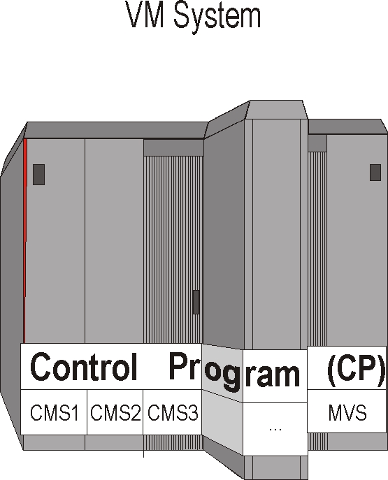
MVS and VM Running on Separate Computers
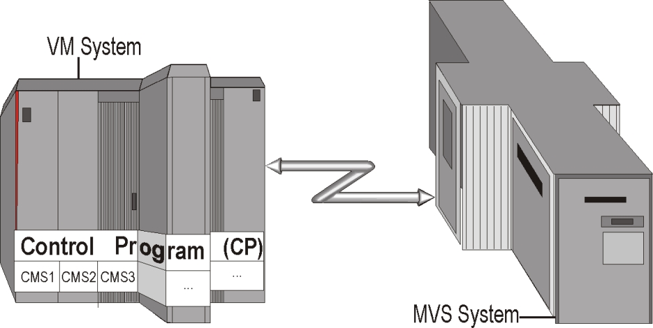
The above VM and MVS systems run on separate computers. However, on some levels, communication exists between the two computers.
The options available for transferring data between the MVS and VM operating systems running on separate computers include the following:
-
If an RSCS machine is operated under VM, then RJE or NJE connections can be established between VM and MVS. This allows jobs and sysouts to be transferred between MVS and VM.
-
If a VM/VTAM machine is operated under VM, SNA connections can be established between MVS and VM. This allows a VM terminal user to invoke the IOA Online interface.
-
If a disk is shared between MVS and VM, a PS or PO file created under MVS can be read under VM.
MVS and VM Running Under LPAR
The LPAR (Local Partitioning) feature in an IBM mainframe allows the installation to (optionally) divide the mainframe into partitions and run multiple operating systems in parallel.
For our purposes, each partition can be regarded as a standalone mainframe computer. Therefore, when partitioning is used, we can regard the processor complex as a type of multi-CPU configuration.
The following figure shows MVS and VM Running Under LPAR:
Figure 29 MVS and VM Running Under LPAR
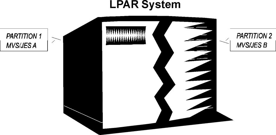
If, as in the diagram above, one partition runs MVS and the other partition runs VM, the previous discussion of VM and MVS running on separate machines is also applicable.
The above discussion of the PR/SM feature also applies to users of MDF (Multi-Domain Facility) from AMDAHL, MLPF (Multiple Logical Processor Facility) from HDS (Hitachi Data Systems), and any other supported CPU with hardware partitioning capabilities.
Invoking the IOA Online Facility From a VM Terminal
If appropriate interactive communication connections are set up between the VM and MVS operating systems, a VM terminal user can log onto an MVS VTAM application that supports the IOA Online facility (for example, TSO, CICS, IMS/DC, IOA VTAM Monitor, IDMS/DC, ROSCOE and COM-PLETE).
All examples in this document assume the use of an IOA VTAM monitor. However, each site must determine which of the previously mentioned MVS VTAM applications is most suitable.
Once the VM user has entered the IOA Online facility, all tracking and control options of Control‑M and IOA are available to the user. For example, the user can add or delete prerequisite conditions, define a new job schedule, order a job, view job run results, hold a job, and so on.
Several methods exist for setting up interactive communication connections, depending on the software and hardware configurations used at each site:
-
dialing into the z/OS computer (MVS under VM only)
-
using VM/VTAM
-
using the IOA Logical Terminal Emulator
-
using a session handling product
Dialing Into the MVS Machine (MVS Under VM Only)
A VM terminal user can dial directly into the MVS machine (at a predefined address), receive the MVS VTAM logon screen, and then log onto the IOA VTAM monitor running under MVS.
Using VM/VTAM
If VM/VTAM is employed under VM, a VM terminal user can dial into the VM/VTAM machine, and then establish (from the VM/VTAM screen) a cross-domain session with the IOA VTAM monitor running under MVS.
Using IOA’s Logical Terminal Emulator
The IOA Logical Terminal Emulator can be employed in conjunction with VM/VTAM. This facility allows the user to establish a VTAM session without leaving CMS. A session can be established in this way with the IOA VTAM monitor running under MVS. At the end of the session, the user remains at the VM/CMS machine.
In addition, the user’s sign-on procedure "can be taught" this option and, on future invocations, can automatically repeat the option. For additional information on this subject, see the IOA chapter in the INCONTROL for z/OS Installation Guide: Installing.
Using a Session Handling Product
There are several session handling products available for the VM environment, such as VM/Pass-through (PVM), Tubes and Vterm.
If such a product is employed under VM, a VM terminal user can use that product to log on the MVS system, and then log on to the IOA VTAM monitor running under MVS.
File Transfer From MVS to VM
General
This chapter demonstrates several techniques for sending a SYSOUT or file to VM. Some of these techniques utilize Control‑M functions. Others utilize standard functions of MVS/JES, VM, and/or other products.
All of the following JCL examples assume that
-
an NJE connection exists between the MVS and VM machines
-
the VM node ID is VMPROD
-
the sysout or report is to be routed to a VM machine (user) named USER1
-
the sysout class is A
Sysouts or files that are sent to the VM user using NJE/RSCS are placed in the VM user’s Reader queue. The VM user periodically checks the user’s Reader queue using the RL (RDRLIST) command. If a file from MVS is found, the user can, for example, browse the file (using the PEEK command) or move it to the A minidisk (using the RECEIVE command).
Routing the Production Job’s Report to VM using JCL
A specific report created by a Control‑M production job can be routed using NJE services to a VM machine (user), simply by defining the destination of the report in the job’s JCL. The following examples demonstrate how to implement this using standard MVS and JES statements:
-
Route the report to a certain VM user using parameter DEST=(node,user) in the appropriate DD statement:
Copy//REPORT DD SYSOUT=A,DEST=(VMPROD,USER1) -
Route the report to a specified VM user using an MVS OUTPUT statement and the report’s DD statement referencing that MVS OUTPUT statement
Copy//JOB1 JOB ...
//OUTREP OUTPUT DEST=VMPROD.USER1
//STEP1 EXEC PGM=...
//REPORT DD SYSOUT=A,OUTPUT=*.OUTREP -
Route printed sysout files of the job to a specified VM user using a JES2 /*ROUTE PRINT statement:
Punched sysout files of the job can be sent to VM using the JES2 /*ROUTE PUNCH statement. A punched SYSOUT file consists of 80-character records. Most sites define JES output CLASS B as a punch class.
Copy//JOB1 JOB ...
/*ROUTE PRINT VMPROD.USER1
//STEP1 EXEC PGM=...
//REPORT DD SYSOUT=A
The following figure shows Routing the Production Job’s Report to VM using JCL:
Figure 30 Routing the Production Job’s Report to VM using JCL

Routing Production Job SYSOUT to VM using JCL
When a Control‑M production job has finished executing, the Control‑M monitor requires that the job’s first three SYSOUT files (SYSDATA) reside in the MVS spool in held mode, in order to analyze how the job has completed. Once the SYSDATA has been analyzed, it can be purged, released for printing, and so on.
Sometimes, the SYSDATA of a Control‑M production job may require routing to a VM user. This can be accomplished by specifying two MVS output statements in the job’s JCL.
These two output statements cause the creation of two copies of the SYSDATA. One copy is assigned standard attributes and can be analyzed by Control‑M. The other copy is directed to the VM machine named USER1.
//jobname  JOB  ...
//COPY1    OUTPUT        JESDS=ALL,CLASS=*
//COPY2    OUTPUT        JESDS=ALL,CLASS=A,DEST=VMPROD.USER1
    .....
Routing Production Job SYSOUT to VM using Control-M SYSOUT Functions
Control‑M SYSOUT functions can route the production job’s SYSOUT (or parts of it) to a VM node. Only the VM node name can be specified (no user ID can be assigned within the destination name). However a JES2 destination ID (defined in JES2 as nodeid.userid) can be specified. As a result, the output is routed to a specific VM user operating in the VM node.
Control‑M can then be used to route selected outputs of a production job (for example, the whole SYSOUT, one or more reports, messages, files) to a specific VM machine (user).
Sending a File to VM in the Form of a Sysout
Control‑M can be used to trigger file transfer to a VM machine. Perhaps the easiest way to perform the file transfer is for Control‑M to schedule a job to run under MVS and produce a SYSOUT file with the appropriate destination.
In the following example, the data to be sent are 80-byte records. In order to print larger data records, use DD statement SYSUT1 to reference a sequential input file that contains these larger data records.
The following figure shows sending a file to VM as a Sysout:
Figure 31 Sending a File to VM as a Sysout
//jobname JOB ...
//PRINT EXEC PGM=IEBGENER
//SYSPRINT DD SYSOUT=*
//SYSIN DD DUMMY
//SYSUT2 DD   SYSOUT=A,DEST=(VMPROD,USER1)
//SYSUT1 DD *
data to be sent
data to be sent
data to be sent
/*
//
File Transfer Product Information
For information about this topic, see File Transfer Products.
Utilize a Shared Disk Between MVS and VM
If a disk or minidisk is shared between MVS and VM, a PS or PO file created under MVS can be read from VM CMS.
Sometimes there is no need to transfer the PO/PS file to VM. Perhaps just a notification is needed to inform the user that the file created under MVS is now available. For a description of various user notification options, see IOA—An Integrated Solution.
For a description of the various VM CMS commands that process and query MVS datasets such as MOVEFILE or STATE, see the relevant IBM manual.
MVS catalog services cannot be accessed in a standard way from VM. Therefore, to read the file, the VM CMS user must know on which disk the file resides.
Triggering an Event in Control-M by a VM User
The following topics describe two techniques for triggering an event in Control‑M. Triggered events can cause Control‑M to run jobs in the z/OS environment, stop jobs from being submitted, order VM-generated jobs into Control‑M, and so on.
Submitting a Job to MVS to Execute a Control-M Utility
A VM user can communicate with Control‑M by submitting a job that invokes an appropriate utility.
For example
-
A VM user can submit a job to MVS that invokes utility IOACND or another IOA/ControlM utility.
-
A job can activate utility IOACND in one of its job steps to add or delete a certain prerequisite condition. Prerequisite conditions can trigger various events in ControlM and IOA (such as, causing jobs to be submitted or stopping jobs from being submitted).
-
A job can invoke a KSL utility. KSL utilities can perform any function that is available under the IOA Online facility.
Prerequisite conditions can also be added and deleted by CMEM, as explained in "Submitting a Job to MVS to be Monitored by CMEM."
By default, all VM-generated jobs receive the same security attributes in MVS, regardless of who generated them. Contact your security administrator about how this problem is handled at your site.
Submitting a Job to MVS to be Monitored by CMEM
The Control‑M Event Manager Facility (CMEM), operating under MVS, can acknowledge a job originating from VM (by its job name) and perform various actions upon arrival or completion of the job or upon specific job execution events.
Sample Functions Available using CMEM
-
Give ControlM full control over job processing.
When a job is submitted by a VM user to MVS, CMEM places a job order for that job in the ControlM Active Jobs File. ControlM treats the job as a regular job.
If the job is submitted with parameter TYPRUN=HOLD in the JOB statement, ControlM releases the job for execution when all scheduling requirements are fulfilled.
When the job finishes execution, execution analysis is performed as usual. If the job order contains post-processing instructions, they are carried out in the same manner as for a regular job.
-
Add or delete a prerequisite condition in case of job arrival or completion.
CMEM can be ordered to add or delete a prerequisite condition when the VM-generated job is displayed on the MVS internal reader, or when the VM-generated job finishes execution in the MVS environment.
For example, CMEM can be ordered to add prerequisite condition SEND-NOW-FILE1 when the MVS system displays a job named VMJOB1. The SEND-NOW-FILE1 prerequisite condition can cause ControlM to submit a job that causes an MVS file named FILE1 to be sent to VM.
The addition or deletion of prerequisite conditions in this manner does not interfere in any way with the execution of the VM-generated job, nor does ControlM analyze execution results for the job.
-
Monitor dataset usage of the job.
CMEM can be ordered to monitor the execution of a VM-generated job with regard to dataset creation, deletion or access.
For example, CMEM can be ordered to add prerequisite condition FILE1-CREATED when a VM-generated job creates a file named FILE1 in the MVS system. Prerequisite condition FILE1-CREATED can trigger a job that sends a user notification back to VM (the following topics describe the various techniques).
For more information, see the CMEM chapter in the ControlM for z/OS User Guide.
Control-M Triggering of Events in VM
This topic demonstrates how to trigger an event in the VM environment. For example, events can be triggered that cause user notification, attach or detach devices, operate a virtual machine in disconnected mode, initiate a backup process, and so on.
Depending on the software and hardware configuration used at your site, there are at least two methods of triggering an event
-
issuing a VM CP Command using IOAOPR (MVS under VM only)
-
executing VM Commands using the IOAVAUTO machine
Issuing a VM CP Command Using IOAOPR (MVS Under VM Only)
If the MVS system is running under VM, you can use utility IOAOPR to issue a VM CP command to VM. Any command that begins with the letters CP followed by a blank is considered by IOAOPR to be a VM CP command.
The MVS machine must be defined with appropriate security privileges and authorizations to enable IOAOPR to issue the commands.
Utility IOAOPR returns a completion code to indicate whether the VM CP command has succeeded. Control‑M can check the completion code and act accordingly. (For example, Control‑M can add or delete a prerequisite condition, reschedule the IOAOPR job after several minutes, and so on.)
If utility IOAOPR is operated under an MVS that is not running under VM, IOAOPR issues an error message if ordered to process a VM CP command.
For additional information about utility IOAOPR, see the INCONTROL for z/OS Utilities Guide.
In the following examples, utility IOAOPR is run as a job, and the VM command to be executed is defined in the PARM field:
/
//jobname  JOB  ...
//COMMAND  EXEC IOAOPR,PARM='CP MSG USER1        JOBA ENDED OK’
This job notifies the VM user, USER1, that JOBA has ended successfully.
This job operates a VM machine named BATCH01 in disconnected mode.
VM/ESA sites can use the XAUTOLOG command instead of the AUTOLOG command.
    //jobname  JOB  ...
    //COMMAND  EXEC IOAOPR,PARM='CP AUTOLOG BATCH01'
Executing VM Commands using the IOAVAUTO Machine
A special VM AUTOLOG machine (called IOAVAUTO below) can be set up to execute commands under VM, and (optionally) inform Control‑M as to whether the commands have been performed successfully.
The IOAVAUTO machine must be defined with appropriate security privileges and authorizations to enable IOAVAUTO to execute the VM commands.
One way in which Control‑M can send a command file to IOAVAUTO is by submitting a job that produces a SYSOUT file to be passed to the VM IOAVAUTO machine. The SYSOUT file can contain one or more REXX commands. The SYSOUT file is passed by JES to VM (RSCS) and is placed on IOAVAUTO’s reader.
The IOAVAUTO machine (driven by EXEC IOAVEXEC) awaits the arrival of command files sent to the machine’s reader. When a reader file arrives, it is received and processed. In addition, the commands processed are logged on minidisk A in file IOA LOG.
Optionally, an indication can be sent to Control‑M as to whether the commands have succeeded, enabling Control‑M to take appropriate action. (For example, Control‑M can trigger another job, reschedule the same commands to IOAVAUTO after several minutes, and handle similar processes).
EXEC IOAVCND is supplied to inform Control‑M as to whether the request has been performed successfully. IOAVCND generates a job and submits it to MVS. The job operates utility IOACND to add or delete a prerequisite condition in Control‑M. The example below illustrates how to call utility IOAVCND.
An important message has to be delivered to VM user USER1.
JOB1 is defined in Control‑M as a cyclic job, with an interval of 20 minutes. JOB1 is triggered by prerequisite condition SHOUT-REQUIRED. The JCL for JOB1 is as follows:
    //JOB1     JOB  ....
    //REQUEST  EXEC PGM=IEBGENER
    //SYSPRINT DD   SYSOUT=*
    //SYSIN    DD   DUMMY
    //SYSUT2   DD   SYSOUT=A,DEST=(VMPROD,IOAVAUTO)
    //SYSUT1   DD  DATA,DLM=@@
    /* REXX EXEC */
    'MSG USER1 Production Job PRDUPDT has abended!'
    IF RC = 0 THEN 'EXEC IOAVCND DELETE SHOUT-REQUIRED 0101'
    EXIT(0)
    @@
    //
JOB1 is submitted by Control‑M upon the creation of prerequisite condition SHOUT-REQUIRED (by another job or process). JOB1 runs under MVS and produces a SYSOUT file containing four REXX statements to be passed to the VM IOAVAUTO machine.
The IOAVAUTO machine reads the file from its reader and processes the command file.
If the MSG command is performed successfully by the IOAVAUTO machine, a job is sent to MVS that deletes prerequisite condition SHOUT-REQUIRED.
If the MSG command is unsuccessful, no feedback is sent back to MVS. As a result, JOB1 is run again by Control‑M (about 20 minutes after its previous run), and another attempt is made to deliver SHOUT message to the VM user.
Issuing a SHOUT Message to a VM User
General
SHOUT is the IOA notification facility by which operations personnel and departmental users are notified of significant events in the production environment. The SHOUT mechanism enables Control‑M to send notifications to VM users instead of, or in addition to, other MVS destinations.
The VM operating system does not employ a function equivalent to the MVS BROADCAST function, which maintains user notification messages. If a SHOUT is issued to a VM user who is not logged on at that time or to a VM user who has suppressed the receipt of messages, the SHOUT is not effective.
The following is a brief list of IOA techniques can be used to send notification messages to a VM user. All of these techniques allow you to verify that the notification message has reached its destination.
-
using utility IOAOPR
-
using the VM IOAVAUTO machine
-
other IOA options
Using Utility IOAOPR
If MVS is running under VM, Control‑M can schedule an IOAOPR job or started task to issue a SHOUT message to a VM user.
For more information about utility IOAOPR and a detailed example of how to issue the notification, see Issuing a VM CP Command Using IOAOPR (MVS Under VM Only).
Using the VM IOAVAUTO Machine
Control‑M can schedule a request to the VM IOAVAUTO machine to issue a SHOUT message to a VM user, and (optionally) inform Control‑M whether the SHOUT has been performed successfully.
For more information about the VM IOAVAUTO machine, and a detailed example of how to set up the notification request, see Executing VM Commands using the IOAVAUTO Machine.
Other IOA Options
Additional options exist if Control‑O or Control‑M/Links for Windows NT operate at the site (detailed in the topics "Control‑O" and "Control‑M/Links for Windows NT").
IOA—An Integrated Solution
The following topics describe some unique facilities in various INCONTROL products that may be of interest to the VM operations staff.
Control-O
Control‑O is the IOA Console Automation Product. The main Control‑O functions relevant to VM are
-
issuing a VM CP command
If MVS is running under VM, ControlO can issue VM CP commands using parameter DO COMMAND.
-
accessing VM machines using KOA
The KeyStroke OpenAccess Facility (KOA) permits two-way communication between ControlO and any VTAM application. If VM/VTAM is operated under VM, ControlO can log onto a VM machine.
Control-M/Links for Windows NT
Control‑M/Links for Windows NT is the IOA Outboard Automation Product, designed to manage multiple heterogeneous systems. The main Control‑M/Links for Windows NT functions relevant to VM are
-
VM system and hardware console support
ControlM/Links for WindowsNT can initiate and perform the IML/IPL process on local or remote VM systems, issue operator commands and automatic responses, and so on.
-
logon to VM applications
The ControlM/Links for WindowsNT 3270 emulation session support enables it to log on to one or more virtual machines running applications.
-
enterprise-wide automation
ControlM/Links for WindowsNT can fully control the MVS and VM systems from a single, centralized point.
Among other things, Control‑M/Links for Windows NT can be used to
-
consolidate console messages from both z/OS and VM consoles in one window
-
coordinate actions across z/OS and VM platforms.
-
For example, when a certain message is displayed on the z/OS console, ControlM/Links for WindowsNT can notify a VM user.
Control-D
Control‑D is the IOA output management or distribution product, providing scheduling and control for every aspect of report processing and distribution.
Report destinations of up to 16 characters can be assigned in all relevant Control‑D print options. Therefore, Control‑D can route selected outputs (bundles) to specific VM machines (users).
Tuning Recommendations
The following recommendations are made with tuning as the primary consideration during the installation of Control‑M. However, some of these recommendations may not be suitable for your site. If necessary, you can make changes at a later stage.
General Tuning Issues
Implementation of LLA/VLF to Control Load Module Fetching
The LLA (Library Lookaside) function of MVS/ESA manages both Linklist and non-Linklist libraries. Therefore, it is not necessary to place the IOA LOAD library in the Linklist in order to benefit from LLA. Without VLF (Virtual Lookaside Facility), the LLA only maintains direct pointers to modules residing in LLA controlled libraries. The combination of LLA and VLF improves module fetching by keeping modules in virtual storage. If VLF has a copy of a module that is controlled by LLA, no I/O operations are required to locate or retrieve the module from a PDS library.
Using Program Fetch Optimization Products
These products can usually speed up the process of locating and/or fetching load modules (even when working with a STEPLIB DD statement). If your data center operates a program fetch optimization product (for example, PDSMAN, PMO, QUICKFETCH), this product can control Control‑M load module fetching.
Placing Control-M/IOA Files on Appropriate Disk Packs
The following disk or file characteristics enable Control‑M to perform optimally:
-
disks that are not very active and are not connected to heavily utilized disk strings and disk channels
-
disks that do not contain MVS system files
-
disks that do not contain a PAGE or SWAP dataset
-
at a multi-CPU site: disks that are not physically reserved (and therefore cannot be physically locked) by other CPUs
-
disks whose head movement is minimized by placing ControlM/IOA files near the VTOC
-
files (IOA RES, IOA LOG, ControlM AJF and History file) that are split over several disks (after installation)
-
disk types that are newer, for example, 3390 and others discussed in "Placing Certain ControlM/IOA Files on Special Disk Devices"
Placing Certain Control-M/IOA Files on Special Disk Devices
Some sites have special disk devices such as
-
solid state (semiconductor) disk devices
-
disks with fixed heads
-
disk controllers with cache memory
Several Control‑M/IOA files are good candidates for placement on these devices.
The (usually temporary) file referenced by DD statement OUT180 is a good example. The first three SYSOUT files of a job submitted by Control‑M are read from spool and written to this file for later analysis. A permanent file can be allocated on an appropriate device and defined in DD statement OUT180 to control the placement of this file.
This file is obsolete if Control‑M/Restart has been installed.
In DD statement OUT180, some customers specify UNIT=VIO (that is, Virtual I/O) to gain I/O performance improvement through the MVS paging mechanism. You should measure your system’s paging performance before considering this.
-
active Jobs File (AJF)
-
IOA Conditions File (CND)
-
ControlM Resources File (RES)
-
IOA Log File
-
If disks with fixed heads are available (for example, 3350 disks with fixed-heads, or equivalent), it may be advantageous to place the first track of the Active Jobs file, and/or the first track of the IOA Log file under the fixed-head areas. The first block of the file contains frequently accessed data and pointers that enable direct access to the respective files.
-
If solid-state semiconductor devices are available, it may be advantageous to place the OUT180 file and/or the RES file on them. Other files can also be considered, depending on the capacity of the devices.
-
If disk controllers with cache memory are available, it may be advantageous to place active ControlM/IOA files on disk packs connected to such controllers. We suggest performing tests in order to determine whether the hit rate observed at your site justifies implementing this recommendation. These tests must be performed after choosing the optimal sleeping interval. For more information, see Choose an Appropriate Sleeping Interval.
-
All of these suggestions have a positive impact on the performance of the Control‑M monitor and other Control‑M components. They also minimize the likelihood of two Control‑M components attempting to access the same resource at the same time.
These suggestions also have a positive impact on the performance of some IOA Online facility screens. For example, optimizing Active Jobs file placement speeds up performance when using Screen 3 of the Online facility. Optimizing IOA Log file placement speeds up performance when using the Screens 5 and 3.L of the Online facility.
Enlarging Control-M/IOA File Blocksize
Most Control‑M/IOA files are created with a predefined blocksize that cannot be changed. For example, the blocksize of the IOA Conditions file (CND), the Control‑M Resources file (RES) and the IOA Manual Conditions file (NRS) are set to 32760.
Control‑M/IOA LOAD libraries are supplied with a blocksize of 6144. Control‑M/IOA source-like libraries are supplied with a blocksize of 3120. These libraries can be reblocked to suit the standards employed at your site. Larger blocksizes reduce I/O, CPU time and elapsed time. However, this does not have a significant impact on the major components of Control‑M.
To increase performance when accessing the IOA LOG file, specify a relatively large block size for the file. For more information, see the INCONTROL for z/OS Installation Guide: Installing, "Installation steps" > "Specify target configuration parameters" > "IOA log file space calculation."
Removing Unneeded and Unused SMF Exits
Control‑M uses the SYSOUT of jobs to perform post-processing. It does not use SMF exits. To release the system resources they use, remove any unneeded or unused SMF exits from the operating system. This is particularly important if you have migrated to Control‑M from a scheduling product that uses SMF exits to perform such post-processing tasks as analysis of the return codes of a step or job.
Control-M Monitor and JES Considerations
The Control‑M monitor uses JES services to receive information about the status of the jobs running in the system.
Control-M tracks all jobs in the JES queue, even though some may await execution due to a lack of system resources (initiators). To prevent this unnecessary overhead, the user may utilize the MAXACTIV parameter in the SELECT section of the CTMPARM member in the IOA PARM library to limit the number of the jobs that Control-M submits by taking into consideration the number of jobs that the Control-M monitor is currently tracking.
This decreases the number of jobs waiting for initiators in the JES input queue and improves the performance of Control-M. The recommended value for MAXACTIV is the number of initiators serving the jobs submitted to Control-M, or a slightly higher number.
JES performance may be affected by long queues of duplicate jobs in SPOOL. When experiencing performance degradation, issue the JES operator command $D DUPJOB to check the maximum length of such the queues. For further details and instructions, contact IBM support.
To improve JES performance in a MAS/SYSPLEX environment, set the SDSB parameter in the CTMPARM member of the IOA PARM library to Y (default).
Control-M uses two types of JES requests to read job output from SPOOL:
-
PSO requests are used when SDSB is set to F. PSO is effected by JES time slicing logic controlled by the HOLD/DORMANCY JES MAS (Multi Access SPOOL) parameters. For more information, see JES2PARM Tuning Considerations.
-
SDSB is used when SDSB is set to Y (or even to N). SDSB is not effected by the high overhead involved in JES slicing.
Run Control-M on the Global Processor in a JES3 Complex
When accessing the JES3 status areas and spool queues, access using the global processor is faster and less expensive than through a local processor. Therefore, we strongly recommend running the Control‑M monitor on the global processor in a JES3 complex.
Run Control-M on the CPU Where Most JES2 Activity Is Performed
In a Shared-Spool complex (MAS), one CPU may perform most of the accesses to JES. For example, this can happen when
-
all or most of the printers are physically connected to one CPU
-
all or most of the jobs are submitted through one CPU
-
all or most of the reports are created on one CPU
-
all or most of the NJE or RJE lines are connected to one CPU
-
one CPU is much stronger (in terms of MIPs) than the others and it effectively monopolizes access to the JES files
If this is the situation at your data center, it is recommend to run the Control‑M monitor on the CPU where most of the JES activity is performed. This optimizes the Control‑M monitor’s communication with JES2.
In general, non-balanced access by different CPUs to JES files can be controlled and balanced through appropriate JES2 parameters.
JES2PARM Tuning Considerations
-
In the CPU on which the ControlM monitor runs, increase the IBMsupplied default (or current) value of PSONUM (number of Process SYSOUT processors) by two or three.
-
To avoid performance degradation of ControlM in a MultiAccess Spool (MAS) environment, adjust and tune the following MAS Definition (MASDEF) parameters:
-
In the CPU on which the ControlM monitor runs, increase HOLD and decrease DORMANCY. In all other CPUs, decrease HOLD and increase DORMANCY.
-
The following recommended values are approximations that do not take into account other products that may be sensitive to JES2 utilization rates resulting from changing the current values. The Systems Programmer may want to do further tuning.
-
-
The HOLD and DORMANCY parameters can by dynamically changed using the following JES2 command: $T MASDEF,HOLD=nnnnnnnn,DORMANCY=(mmmm,nnnn)
-
For information on avoiding performance degradation of ControlM in a non-MAS environment, see "Member-specific Parameter Recommendations" (for hold and dormancy in the MASDEF statement) in the Accessing the Checkpoint Dataset topic of the IBM manual JES2 Initialization and Tuning Reference.
In particular, note the following recommendation made by IBM:
"If running a single-processor, the following parameter specifications might be good initial values because there are no other processors waiting to gain access to the queues:"
Copy+------------------------------------------------------------------------+¦
MASDEF HOLD=99999999,DORMANCY=(10,500)
+------------------------------------------------------------------------+:
This change enables the JES on the CPU on which Control‑M runs to handle Control‑M requests more efficiently and thereby avoid delays in Control‑M’s analyzing a job’s ending status.
From the Control-M point of view, there are two JES dependent time intervals:
-
the time interval when the JES checkpoint is available (JES window),
-
the time interval between the JES windows.
The optimal value of the MULTISUB parameter is the smaller of the following two numbers:
-
the max number of prepared jobs that Control-M can write into the JES internal reader during an interval (1).
-
the max number of jobs that Control-M can prepare for mass submission during an interval (2)
Since time of job preparation is strongly affected by the system operational environment (CPU utilization, I/O time etc.) and also by the JES MAS definitions, it is impossible to say, a priori, how the optimal value MULTISUB should be calculated. Nevertheless it is clear that slowly incrementing the MULTISUB value will have a positive performance effect until reaching an optimal (critical) value. Exceeding such an optimal value might cause some performance degradation.
Note that in any case, better performance is always achieved by choosing some value for the MULTISUB parameter rather than relying on its default value.
Control-M in a Parallel Sysplex Environment
In a Parallel Sysplex environment with JES2 working in a multi-access spool (MAS) configuration, better Control‑M performance may be achieved by using the CTMPLEX facility. For more information, see CTMPLEX: Control-M for the Sysplex.
Control-M and SMF Processing
Since the Control-M monitor is a long-running job, it may take a long time from when the monitor is stopped until it actually ends, depending on how the customer has set the DDCONS parameter in the SMFPRMxx system PARMLIB member.
When DDCONS is set to YES, long-running jobs may take a long time to end because of the building of SMF type 30 records. If such delays can or do adversely affect the production system, the user should consider setting DDCONS to NO. This setting will bypass the consolidation function for type 30 records, thereby reducing the processing time required to build the records, and thus also the time required to complete the job. For more information, see the IBM manual MVS Initialization and Tuning Reference.
NJE Diagnostic Procedures
An NJE job is a job submitted by the Control‑M monitor for execution on a remote node. Control‑M can detect the status of jobs running on a remote node, and when these jobs finish executing, Control‑M can assign a status to them.
To analyze how a job finished executing, Control‑M uses JES services to read the job’s output. If Control‑M detects a critical error in JES operation, it shuts itself down. This prevents the incorrect submission of jobs due to a JES malfunction.
Errors can occur under the following circumstances:
-
ControlM cannot read the job SYSOUT.
-
The job returned with a temporary job status because its current job number is not the same as the job number it had when it started. ControlM must know that the job number changed and must change the previous job number to the new one. The ControlM monitor can detect that the original job ID of the NJE job is being used by another job and continue to search for a job to match the new job ID.
-
If the assigned job number changes, ControlM may act as if the old job disappeared.
-
The job can have more than one sysout when it returns with a temporary job status. This gives it 2 separate ID numbers.
-
A job was purged from the spool on the remote node. The following message may be displayed each time Control-M attempts to find the job on the remote node:
CopyHASP693 JOB NOT FOUNDBMC recommends that you do not do purge jobs on the remote node.
-
If the remote node is not active or not connected to the home node, the following message may be displayed each time Control-M attempts to find the job on the remote node:
CopyHASP674 SYSTEM UNCONNECTED
This can be rectified by activating the remote node or by reconnecting the home node and the remote node.
To determine the cause of a specific error, it may be necessary to provide the Control‑M administrator with specific information about the job. The following suggestions can help resolve the problem:
-
Check the maintenance levels of the CTMSUB module and the CTMSPY module.
-
Check the job in the Zoom screen (Option Z on the Active Environment screen). Verify that the NJE field is set to Y (Yes) and that the NODE field contains the correct name of the remote node.
-
Look at the job’s JCL stream and see whether any statement contains parameter ‘FREE=CLOSE’.
-
Send the ControlM administrator the job SYSOUT and the SDSF screen or the output of any other comparable product showing the SYSOUT datasets.
The SYSOUT status and whether the job was deleted or purged displays in the SDSF screen. If, for example, the SYSOUT datasets are in the wrong OUTPUT CLASS, ControlM cannot read them.
-
Indicate if this problem occurs frequently and whether it occurs for all jobs or for just specific types of jobs.
-
Indicate the type of job (for example, cyclic, short or long term, regular, CICS).
-
Ensure that parameter ENHNJE (in the CTMPARM member of the IOA PARM library) is set to Y.
-
Ensure that the messages $HASP890, $HASP608, $HASP693, $HASP826, and $HASP650 are not suppressed. Also, do not suppress messages starting with the name of the remote system.
BMC recommends that you do not purge jobs from the spool on the remote node. However, if a job was purged from the spool on the remote node, you must notify Control‑M of the event, by changing the value in the NJE field in the Active Environment Zoom screen (Screen 3.Z) to ' ' (Blank). After a short time, the status of the job changes to Disappeared.
If the remote node is not active or not connected to the home node, you should activate the remote node or reconnect the home node and the remote node. If this is not possible, you must notify Control-M of the event by changing the value in the NJE field in the Active Environment Zoom screen (Screen 3.Z) to ' ' (Blank). After a short time, the status of the job changes to Disappeared.
If the previous suggestions do not resolve the problem, perform the following procedure:
To open a BMC Customer Support case for an NJE issue
-
In member CTMPARM of the IOA PARM library, set parameter DBGMCS=Y.
-
Restart the Control-M monitor
-
Set traces 33, 39, and 79 by issuing the following MVS modify command:
where ctm is the name of your Control-M monitor STC.
CopyF ctm, TRACE=(33,39,79) -
Reproduce the problem.
-
Reset the CTMPARM parameters to their original value and turn off the traces.
-
Send the following documentation to BMC Customer Support:
-
Job print-screen of 3.Z
-
Complete joblog of Control-M monitor STC
-
IOALOG from the relevant period of time
(Use IOACPLG1 from IOA.JCL library to copy the log to a sequential file.) -
Extracts from the syslogs of the system where CTM runs and the remote system
-
NJE job sysout and the SDSF screen (or the output of any other comparable product) showing the sysout datasets
-
Assign Appropriate Priority to the Control-M Monitor
Use MVS System Resources Manager (SRM) parameters to assign an appropriate priority so the Control‑M monitor can receive enough CPU and other computer resources to perform the necessary tasks.
Appropriate priority must also be assigned to JES, because the Control‑M monitor communicates extensively with JES.
Online-oriented sites that run JES with low priority during service hours must increase the priority of JES before main batch processing begins. This can be done automatically by scheduling a CTMOPR started task at the appropriate time to issue an appropriate SET ICS and/or SET IPS command.
Run the Control-M Monitor as Non-swappable
Set parameter NONSWAPM to Y in member CTMPARM in order to activate the Control‑M monitor as non-swappable. For more information, see the Control‑M chapter in the INCONTROL for z/OS Installation Guide: Installing.
This causes Control‑M to be paged-in and paged-out according to a more economical algorithm. In addition, this speeds up the paging process by causing some basic address-space related pages to remain in virtual storage. Non-swapping mode ensures good response for the Control‑M monitor, as well as the best overall performance.
If the Control‑M monitor is run as swappable, the Control‑M status tracking task may get stuck waiting for a JES response. This can happen if the monitor communicates with an overloaded JES.
Choose an Appropriate Sleeping Interval
The Control‑M monitor "wakes up" according to the sleeping interval specified using parameter INTERVLM in member CTMPARM.
As the value specified for the sleeping interval increases, Control‑M uses less CPU and I/O for the following reasons:
-
The job selection routine is invoked after longer intervals.
-
The ControlM monitor checks the status of submitted jobs after longer intervals.
-
The ControlM monitor interrogates the Active Jobs file (AJF) after longer intervals for additions or changes that may have been performed from batch or from the IOA Online facility.
However, if the value specified for the sleeping interval is too high, the following can result:
-
Jobs may be scheduled with a delay.
-
Processing a command entered using the IOA Online facility (for example, to hold a job) may take more time because the ControlM monitor performs the command.
Do not overrate the importance of a job-scheduling delay. In many cases, increasing parameter INTERVLM from three seconds to six seconds can actually provide the same throughput, because many jobs that were submitted by Control‑M must wait for an initiator to become available.
The sleeping interval is not a fixed installation parameter. It can be changed dynamically during standard production hours (for example, according to hours, shifts, and so on), by scheduling a CTMOPR started task at the appropriate time. The started task issues the command
F CONTROLM,INTERVAL=ss[.th]where
-
ss is the interval in seconds
-
th is the interval in hundredths of seconds
Another aspect to consider when deciding on the value of parameter INTERVLM is avoiding situations where the Control‑M monitor is faster than the local JES. This can be recognized when one of the following events occurs:
-
Many CTM262S/JES262S messages are issued by the ControlM monitor for different jobs. This happens when the job’s SYSOUT is already on the JES output queue, but JES does not allow access to it.
-
The ControlM monitor successfully submits a job to MVS, but the job does not appear in any JES queue for a long time, causing the job to receive a status of "disappeared". This situation is rare and only happens if JES is heavily overloaded.
This does not refer to a situation where JES is "stuck." Control‑M does recognize such a situation, and therefore does not submit the job.
If this happens at your site, consider increasing the value of parameter INTERVLM.
Storage Isolation
Storage isolation (also called "storage fencing") limits the number of page frames that can be "stolen" from an address space. You can specify a minimum or maximum WSS (working set size), a minimum or maximum paging rate, or a combination of the two. The related MVS SRM parameters are: CPGRT, CWSS, PPGRT, PPGRTR and PWSS.
Improper specifications can degrade the Control‑M monitor’s performance and/or overall system performance. For example, if the maximum WSS is too low, the Control‑M monitor’s performance may suffer.
You only need to consider storage isolation if you experience a serious paging problem in the Control‑M monitor address space, causing delays in job scheduling.
In any case, you should not specify a maximum WSS and continue to monitor performance on a periodic basis.
Tuning the Online Facility
Preallocate Required Control-M/IOA Files in TSO Logon Procedures
If entry to the Online facility is slow due to allocation problems, consider pre-allocating the required Control‑M/IOA files in the TSO Logon JCL procedure, instead of in the Control‑M/IOA CLISTs. JCL allocations are faster than TSO dynamic allocations. However, you should only consider doing this if there is no other way to speed up MVS allocations at your site.
Try to Eliminate TSO STEPLIBs
In general, TSO STEPLIBs may cause performance problems. Whenever a program is to be fetched, CPU cycles and I/O are used to search the STEPLIB directories for the program to be fetched. If the program is not located, an additional search is performed in Linklist. For more information, see General Tuning Issues.
Use the IOA Online Monitor When Required
If you need to assign different performance groups for work done under the IOA Online facility and other online work, use the IOA Online monitor (for TSO or ROSCOE). For additional information, see the IOA chapter in the INCONTROL for z/OS Installation Guide: Installing.
When using the IOA Online monitor, only terminal-related issues are performed under TSO/ROSCOE. All other work is performed in the external server address space.
TSO or ROSCOE users are given their standard performance definitions. The external server address space definition can differ from the MVS SRM (for example, it can have a higher priority).
Mirror File (Dual Checkpointing Mode) Considerations
The Control‑M monitor can work in dual mode. In dual mode, the Control‑M monitor maintains duplicate copies of the Control‑M Active Jobs file, the Control‑M Resources file, and the IOA Conditions file. If a disk crash makes the files inaccessible, the mirror files can immediately replace them.
The DUALDB parameter determines dual mode operation. For more information, see the INCONTROL for z/OS Installation Guide: Installing, "Installation steps" > "IOA datasets characteristics" > "Mirror file for IOA conditions" > "Additional parameters."
Because of performance considerations, BMC no longer recommends using the mirror file mechanism. Instead—for backup and recovery—use the Control-M Journaling facility, described in Journaling. By using Journaling, you can avoid the performance loss associated with mirroring, taking advantage of the increased efficiency and integrity features built into modern storage devices.
Control-M Event Manager (CMEM) Considerations
The overhead required to operate CMEM is insignificant because
-
Every WTO message is passed to CMEM by MVS.
-
CMEM only tracks $HASP001, $HASP100 and $HASP395 messages (under JES2) or IAT6101, IAT6108, IEF403I, IEF404I, IEF450I, and IEF4531 messages (under JES3). In addition, all MVS and JES messages of jobs to be controlled by the above facilities are tracked as well. All other messages are immediately passed back to MVS. When a relevant message is encountered, the following actions are performed:
-
CMEM checks whether the related job or event has been defined in a CMEM table. This search is performed in storage because the CMEM table is loaded into storage when CMEM is initialized.
-
If the job or event has not been defined in a CMEM table, CMEM passes the message back to MVS.
-
If a relevant event is encountered, the CMEM rule passes the FORCEJOB and RESOURCE requests to the ControlM monitor, which performs the requests. The STOPJOB and CONDITION requests are performed by the CMEM monitor.
-
All CMEM activities (except the last item above) are performed in storage. No I/O or supervisor calls are required. Therefore, no special tuning activities have to be performed and there is no reason to monitor CMEM performance.
Control‑M monitor overhead can easily be monitored by any locally employed performance tool.
IOA Parameters, Control-M Parameters and Optional Wishes
Many Control‑M parameters, IOA parameters and optional wishes directly affect Control‑M performance and behavior in various areas. For more information about these parameters and wishes, see the customization process for Control‑M in the Control‑M chapter of the INCONTROL for z/OS Installation Guide: Customizing, and the following members:
-
IOADFLT in the IOA IOAENV library
-
CTMPARM in the IOA PARM library
To optimize Control-M performance and behavior, review and customize the IOA Profile variables described in Profile Variables.
Single and Multiple CPU Configuration and Support
This section describes how Control‑M is implemented under multiple CPU hardware and software configurations. A number of scenarios are provided, relating to specific hardware connections or to specific enterprise connections.
This section also describes the scope of production workload control and various Control‑M options that can be used. It does not cover Control‑M’s entire range of methods and possibilities, but just the most common ones.
The basic Control‑M system for both single-CPU and multi-CPU configurations contains the following major components:
-
monitor
-
online facility
-
online monitor (optional)
-
utilities
-
KSL facility
-
CMEM facility (optional)
Single-CPU Configuration
This section describes how a single CPU is configured with both single and multiple Control‑M systems.
Single-CPU Configuration with Single Control-M System
The following figure shows a Single-CPU configuration with a Single Control‑M System:
Figure 33 Single-CPU Configuration with Single Control-M System
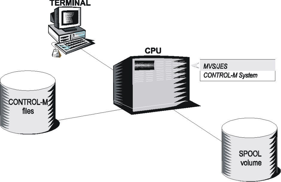
In the configuration illustrated above, Control‑M is running on one mainframe computer. It includes
-
at least one disk volume containing the JES Spool
-
at least one disk volume containing the IOA Core and ControlM Repository
-
at least one terminal capable of operating the IOA and ControlM Online facilities
Standard terminals of the 3270 family are supported as well as other devices that emulate a 3270 terminal (such as a PC with 3270 simulation or a VT100 with 3270 simulation).
IBM DBCS terminals (or equivalent), which provide Japanese language (Kanji) capability, are supported as well.
Optionally, an RJE (Remote Job Entry) workstation (or an intelligent system that emulates an RJE station) can be connected to the mainframe. Under JES3, the same facility is called RJP (Remote Job Processing).
The following Control‑M features support RJE:
-
The ControlM Event Manager (CMEM) can be used to
-
acknowledge and handle jobs submitted from RJE to MVS
-
acknowledge the creation or deletion of datasets by jobs that originated from RJE
-
-
ControlM SYSOUT options support the routing of SYSOUTs to RJE.
-
RJE jobs can invoke utility IOACND, or other IOA and/or ControlM utilities using a JCL step to communicate with ControlM.
Single-CPU Configuration with Multiple Control-M Systems
A configuration in which two Control‑M systems operate is common because many sites install a Control‑M production system and a Control‑M test system. We recommend operating a separate Control‑M test system for testing new versions or options before applying them in the Control‑M production system. Usually, the Control‑M production system and Control‑M test system are separate systems that use separate libraries, separate databases, different JCL procedures, and so on.
In some cases, there may be good reasons for operating two or more Control‑M production systems. For example, a service bureau may need to provide distributed scheduling for two or more clients.
Two Control‑M systems can communicate with each other by scheduling special jobs. For example, Control‑M system A may schedule a special job that invokes utility IOACND, which adds a prerequisite condition to the IOA Conditions file base of Control‑M system B. This prerequisite condition, in turn, triggers the submission of a job by Control‑M system B.
Subject to system resource limitations any number of Control‑M systems can be operated concurrently on a single mainframe.
For additional information about how to activate more than one Control‑M monitor, see the Control‑M chapter in the INCONTROL for z/OS Installation Guide: Installing.
Each Control‑M system uses a separate CMEM subsystem. Subject to system resource limitations, any number of CMEM subsystems can be operated concurrently. However, a job can be handled by only one CMEM subsystem.
Different (several) CMEMs can be used to acknowledge job-arrival or job-ended events for a job. However, use only one CMEM to acknowledge ON DSNEVENT or ON STEP events.
Multi-CPU Configuration
Shared Spool Configuration with ENQ-Handling Product
The following figure shows a Shared-Spool Configuration with an ENQ-Handling Product:
Figure 35 Shared-Spool Configuration with an ENQ-Handling Product
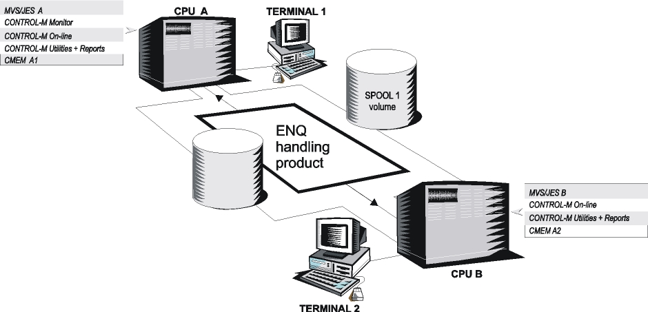
The term "Shared-Spool" refers to "JES2 Multi-Access Spool (MAS)" or "JES3 Complex" connections between two or more MVS systems.
A Shared-Spool configuration consists of two or more JES systems sharing JES input, job, and output queues. The Shared-Spool must reside on one or more disk volumes that are shared by (connected to) all relevant mainframes.
The above diagram shows a basic Shared-Spool configuration consisting of two mainframes.
The following discussion also applies to Shared-Spool configurations with more than two mainframes.
A single Control‑M monitor is sufficient for handling the entire Shared-Spool complex. The monitor submits all jobs to CPU A but the jobs run under the appropriate CPU (CPU A or CPU B).
A job can be designated to run on a specific CPU based on the value of parameter CLASS in the JOB statement. If a job submitted by the Control‑M monitor specifies a CLASS that is only served by CPU B, JES automatically designates the job to run on CPU B.
A job can also be designated a job to run on a specific CPU through an appropriate JES statement, such as the following:
/*JOBPARM SYSAFF for JES2;
//*MAIN SYSTEM for JES3.
If a job submitted by the Control‑M monitor requests (through such a statement) to run on CPU B, JES automatically sends the job to CPU B.
CLASS and SYSAFF/SYSTEM specifications can be hard-coded in the job’s JCL, or can be determined dynamically and set by the Control‑M monitor during job submission.
For information on dynamically setting up CLASS and SYSAFF/SYSTEM specifications using the AutoEdit facility, see the examples of controlling the target computer by class and system affinity in the JCL and AutoEdit facility chapter of the Control‑M for z/OS User Guide.
Control‑M supports dynamic CPU workload balancing. This type of balancing is achieved through the use of quantitative resources and the Automatic Tape Adjustment facility. For more information, see the description of the RESOURCE Runtime scheduling parameter in the job production parameters chapter of the Control‑M for z/OS User Guide.
Assuming that the IOA and Control‑M software, Core, and Repository reside on a disk that is shared by the two CPUs, the Online facility can be invoked under both CPUs. For the same reason, the various IOA and Control‑M utilities and reports can be operated on both CPUs.
Special steps must be taken in order to simultaneously update a file from two CPUs. Before Control‑M updates the Repository, it issues a special ENQ with a scope of SYSTEMS. An ENQ-handling product (such as GRS or MIM) must be employed in order to pass the ENQs to all CPUs and synchronize the updates. If no ENQ- handling product is employed, data integrity is jeopardized.
Ensure that the ENQ-handling product actually handles the Control‑M ENQs. The easiest way to verify this is to enter Screen 3 of the Control‑M Online facility under CPU B, and look at the upper right corner. If the Control‑M monitor is up under CPU A, the status "UP" is displayed.
The Control‑M Event Manager (CMEM) can acknowledge the arrival or ending, of jobs or started tasks, accesses to dataset, and changes to dataset disposition (allocation, deletion, cataloging and uncataloging) performed by jobs or started tasks. If you want to receive these acknowledgments on both CPU A and CPU B, the CMEM component must operate on both CPUs.
Additional Control‑M options provide special support for the Shared-Spool environment
-
SHOUT (notification) messages can be issued to users on any CPU. For further information about parameter SHOUT, see the job production parameters chapter of the ControlM for z/OS User Guide.
-
A started task (STC) can be scheduled on any CPU. For further information about parameter MEMLIB, see the job production parameters chapter in the ControlM for z/OS User Guide.
-
Operator commands can be issued in any CPU. For further information about the IOAOPR utility, see the INCONTROL for z/OS Utilities Guide.
Assuming that the Control‑M monitor runs on CPU A and a command is to be issued to CPU B, any of the following methods can be used:
-
The monitor can schedule a job or started task to run on CPU B and invoke procedure IOAOPR to issue the command.
-
The monitor can schedule the IOAOPR STC (or job) to run on CPU A and issue the command in such a way that it is passed to CPU B (Under JES2, use the $M command. Under JES3, use the *T command.)
-
Sample Exit IOAX034A in the IOA SAMPEXIT library enables the user to issue operator commands by running a dummy job without scheduling a job or a started task using SHOUT requests.
This sample exit is suitable for all JES2 and JES3 versions (assuming that the Control‑M Monitor runs under the global JES3 processor).
You should use the first method for the following reasons:
-
The command always reaches CPU B.
-
ControlM analyzes the SYSOUT of the scheduled job or started task.
-
Checks whether the job or started task ran successfully or not.
-
This method provides advantages from a security point of view.
Control‑M job statistics are maintained separately for each CPU These job statistics are used as input for the Control‑M Simulation and Forecasting facility. These statistics can be viewed in Screen 3.S.
From a technical point of view, the Control‑M monitor can run under any CPU. For performance considerations, Tuning Recommendations.
Shared Spool Configuration – Without an ENQ-Handling Product
This environment is identical to the previous environment except that no ENQ handling product is employed. Another difference is that the shared Spool might or might not be connected to CPU B.
You should not use this configuration.
Only one Control‑M monitor is required for handling the entire shared SPOOL complex. Aside from the following restrictions, all the capabilities also apply to this configuration:
-
To avoid jeopardizing data integrity, the ControlM Repository must not be updated from CPU B. Therefore, all ControlM components (Monitor, Newday procedure, utilities, KSLs that update IOA and ControlM files, and so on) must run exclusively on CPU A.
-
If the optional CMEM facility is operated on both CPU A and CPU B CMEM must be given read access to the IOA LOAD library and ControlM monitor to-subsystem Communication file plus write access to the subsystem-to-ControlM monitor Communication file. All files that are required by CMEM must reside on a shared disk. This shared disk does not need to contain general IOA and ControlM files. (CMEM can operate in a multi-CPU environment without an ENQ handling product.)
-
To make sure that ControlM files are not updated from CPU B, one or both of the following options must be implemented:
-
Option 1: Use your site’s security product (RACF, ACF2 or Top Secret) to deny write or update access to the IOA and ControlM files from CPU B.
-
Option 2: Vary off-line (under CPU B) the disks on which IOA and ControlM files reside. This method is applicable only if the disks do not contain other files. There may also be a problem if CMEM is operated.
-
Option 2 is the most effective method, but may be difficult to implement at most sites, because ControlM uses only a portion of a disk and does not require a dedicated disk. Option 1 is the easiest to implement at most sites.
-
As illustrated in the diagram above, terminal TERM 2 is physically connected to CPU B. However, this terminal can be used to operate the IOA Online Facility.
-
If CPU A and CPU B maintain an appropriate cross-domain SNA connection through a CTC, 37xx communication controller (or equivalent) or Token Ring connection, then the terminal user can log on to VTAM application running in CPU A and invoke the IOA Online Interface. Relevant VTAM applications are: TSO, ROSCOE, IOA VTAM monitor, CICS, IMS/DC, and any VTAM application that supports the IOA Online Facility.
Shared-Spool Configuration with Multiple Control-M Production Systems
This environment might or might not use an ENQ-handling product. DISK 1 may or may not be connected to CPU B. DISK 2 may or may not be connected to CPU A.
The following figure shows a Shared-Spool configuration with Multiple Control‑M Production Systems:
Figure 37 Shared-Spool Configuration With Multiple Control-M Production Systems
Some users employ two Control‑M production systems in a Shared-Spool environment. Each system employs a separate Repository. Because a single Control‑M system is sufficient for controlling the whole Shared-Spool environment, two production systems are not required and, in fact, increase the requirement for disk space, resource consumption and maintenance. However, the following examples describe situations that can justify using two Control‑M production systems.
Some sites are service-bureaus that dedicate a whole mainframe to one customer.
If each mainframe in a Shared-Spool environment is dedicated to a different customer and each customer requires the services of Control‑M, then it is desirable to distribute the scheduling of production work and operate a separate Control‑M system for each customer.
A bank operates two CPUs in a Shared-Spool environment. Each CPU is used for a different task – one handles activities related to the stock market; the other for handles all other activities of the bank. To maximize reliability and availability the bank operates two separate Control‑M production systems. When one CPU goes down (for any reason), the other continues performing its tasks.
These two Control‑M systems communicate with each other by scheduling special jobs. For instance, Control‑M system A can schedule a special job that invokes the utility IOACND to add a prerequisite condition in the IOA Conditions file of Control‑M system B. This prerequisite condition can in turn trigger the submission of jobs by Control‑M system B.
CMEM Operation
If each CPU is fully controlled by its Control‑M system, only one CMEM subsystem is required on each CPU. The CMEM that is part of Control‑M system A runs on CPU A. The CMEM that is part of Control‑M system B runs on CPU B.
However, if each Control‑M system must acknowledge events that might occur under both CPUs, each CPU must operate two CMEM subsystems (one for Control‑M system A and the other for Control‑M system B). However, a job can be handled only by one CMEM subsystem.
The following table shows the number of CMEM subsystems needed for handling events:
Table 119 Number of CMEM Subsystems Needed for Handling Events
|
Event |
Number of CMEM Subsystems |
|---|---|
|
ON JOBARRIVAL |
All CMEM Subsystems |
|
ON JOBEND |
All CMEM Subsystems |
|
ON DSN |
One CMEM Subsystem |
|
ON STEP |
One CMEM Subsystem |
Multi-CPU Configuration With Shared-DASD Only
The following figure shows a Multi-CPU configuration with Shared DASD only:
Figure 38 Multi-CPU Configuration with Shared DASD Only

This configuration consists of two mainframes that only employ shared DASD (that is, there is no shared Spool). Each CPU runs its own Control‑M system.
DISK 1 may or may not be connected to CPU B. DISK 2 may or may not be connected to CPU. A The IOA/Control‑M Core and Repository do not need to reside on a shared disk.
However, a shared IOA Condition file is necessary to support this environment. It enables communication between two Control‑M systems that run in different CPUs and are not connected using a shared Spool.
Communication is established by sharing prerequisite conditions. These shared prerequisite conditions enable the two Control‑M systems to know the status of production work in both CPUs.
The two CPUs must employ a global ENQ-handling product (such as GRS or MIM). For further information see the SHRQNAM parameter in the IOA chapter of the INCONTROL for z/OS Installation Guide: Installing.
CMEM Operation
If each CPU is fully controlled by its Control‑M system, only one CMEM subsystem is required on each CPU. The CMEM that is part of Control‑M system A runs on CPU A. The CMEM that is part of Control‑M system B runs on CPU B.
However, if, each Control‑M system must acknowledge events that may occur under both CPUs, then each CPU must operate two CMEM subsystems (one for Control‑M system A and the other for Control‑M system B.
NJE Network of MVS Nodes
The following figure shows a NJE Network of MVS Nodes:
Figure 39 NJE Network of MVS Nodes
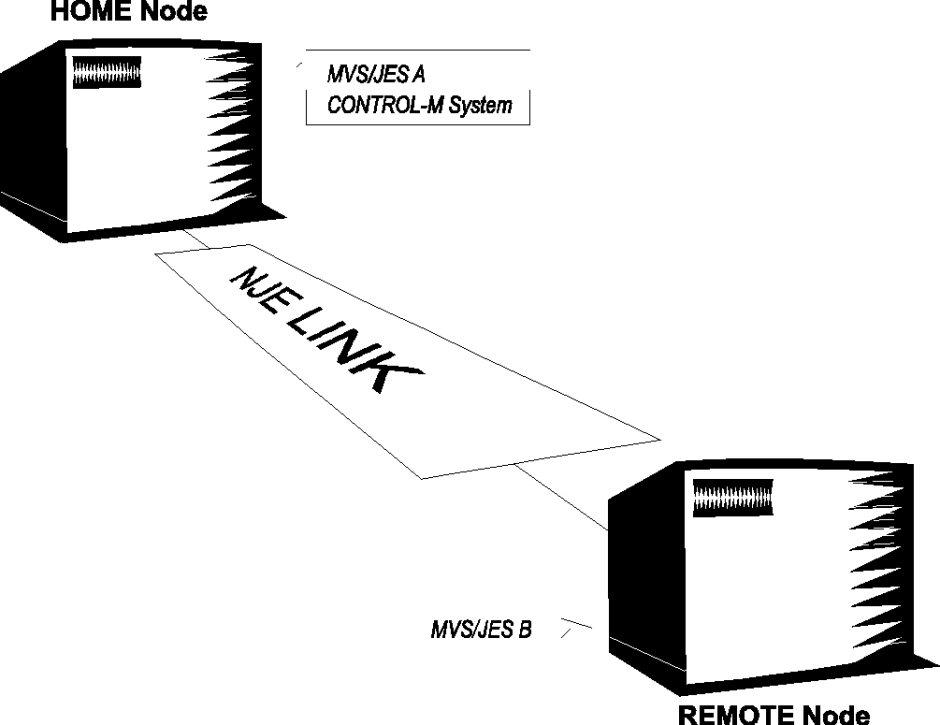
MVS-to-MVS NJE Connection
This diagram shows a network consisting of two nodes. For this discussion, the node that operates the Control‑M system is called the Home node. All other node are called Remote nodes.
Many Control‑M sites employ a network consisting of two MVS computer systems (nodes) connected using an NJE (Network Job Entry) link.
This type of network is usually used to connect two z/OS computers that are distant from each other. However, some sites use this type of network between two CPUs in the same room for security reasons or during a transitional phase.
To make use of and control such a network, Control‑M may run on one CPU (called the Home node) and submit selected jobs to another CPU (the Remote node). The jobs run at the Remote node and the SYSOUT (or the SYSDATA) is returned to the Home node for analysis by Control‑M.
For a more detailed discussion on this subject, see member DOCMNJE in the IOA DOC library.
The Remote node can operate a separate Control‑M system. In this case, production work in the Remote node must be controlled by its own Control‑M system. However, the Home node can still send selected jobs to the Remote node.
Each Control‑M system can communicate with the other by submitting special jobs to the other CPU. For example, a special job may invoke utility IOACND to add, delete or check for the existence of a prerequisite condition.
The following Control‑M options provide special support for the NJE environment:
-
issuing a SHOUT (notification) message to users in a Remote node
-
scheduling a started task (STC) in a Remote node
-
issuing operator commands in a Remote node
-
maintaining job statistics by ControlM
-
handling jobs originating in the Remote node operating CMEM in the Home node
If an enterprise network consists of three MVS nodes (named Node A, Node B, and Node C), the number and location of Control‑M systems that must be employed depends on the structure and goals of the enterprise.
A single Control‑M system is sufficient to submit production work to the whole network. However, specific organizational structures or goals may make it desirable to operate more than one Control‑M system. If the enterprise operates in a centralized manner, a single Control‑M system may be sufficient. If not, multiple Control‑M systems might be more appropriate.
Availability considerations
Control‑M may be affected by events occurring on the node where Control‑M runs. For example, system down (regular maintenance or system crash), disk crash, and line-down problems.
If Control‑M is employed on a single node, such events affect the whole network. However, if, each node employs its own Control‑M system, only one part of the network is affected.
Performance considerations
If many jobs are to be transferred through the communication lines, multiple Control‑M systems must be considered (to cut down the communications overhead).
The overhead for sending jobs is usually insignificant. It is usually jobs’ reports that utilize the communication lines the most when they are sent back. Control‑M only requires the SYSDATA to be sent back, which is also insignificant in regard to the communications overhead).
Disaster and backup planning
Overall disaster and backup planning requires that important production work be switched within a short time from one node to another. If each node already employs its own Control‑M system, the transfer can be performed quickly and easily.
Special Considerations
Mainframe with LPAR
The LPAR (Logical Partitions) feature in an IBM mainframe allows a site to divide its mainframe into "partitions" and run multiple operating systems in parallel.
For our purposes, we can treat each partition as a standalone mainframe computer and we can treat the processor complex as a type of "multi-CPU configuration."
To determine how Control‑M controls the production work in two logical partitions, we need to determine what connection (if any) exists between the two partitions. Relevant connections are: shared SPOOL, shared-DASD only, and NJE.
If an MVS system runs in both partitions and the only connection between them is shared-DASD, then the description Multi-CPU Configuration With Shared-DASD Only also applies to this configuration.
In addition, these considerations apply to other supported CPUs with hardware partitioning capabilities, which can be operated in either "single image mode" or "partition mode."
Operating MVS Systems Under VM
For information about this topic, see Control-M VM Support.
Support of Other Platforms (Such as VM, DOS/VSE, AS/400, DEC, HP)
This discussion deals only with Control‑M z/OS products. For information about other products, see the appropriate Control‑M publications.
This diagram deals with a multi-CPU environment that includes one or more non-z/OS computers. The most common non-z/OS platforms are: VM, DOS/VSE, AS/400, DECs VAX/VMS, and HP.
The following discussion shows how a z/OS-based Control‑M system can contribute to this environment:
The z/OS-based Control‑M can
-
schedule work in the non-MVS system
-
control production work that is scheduled by a non-MVS system to run on the MVS system
-
trigger events on the non-MVS system
-
interact with any hardware that supports an "appropriate connection" to the z/OS computer
-
Some of these "appropriate connections" are listed in the following topic.
RJE/RJP
Many systems use hardware and software to emulate an RJE station connection to an MVS system. For example, the following systems can emulate an RJE station: VM/RSCS, VSE/POWER version 1, DECNET/SNA RJE, AS/400 RJE, and HP SNA/NRJE.
Control‑M has several features that support RJE, such as
-
ControlM Event Manager (CMEM), which can be used to acknowledge and handle jobs submitted from RJE. CMEM can be used to acknowledge the creation or deletion of datasets by jobs that originated from RJE.
-
ControlM SYSOUT options, which can support the routing of SYSOUTs to RJE. RJE jobs can use utility IOACND or other IOA/ControlM utilities to communicate with ControlM.
NJE (SNA)
MVS/JES can set up an NJE connection with non-MVS systems that employ compatible networking facilities. For example, MVS/JES NJE connections can be set up with IBM VM/RSCS, IBM VSE/POWER version 2, IBM AS/400 using VM/MVS Bridge, and DEC VAX/VMS systems (through 1nterlink or Jnet).
An NJE connection provides the ability to transmit and receive jobs, in-stream datasets, sysout datasets, commands, and messages from one computer system (node) to another.
The ability to send in-stream datasets using jobs is limited by data structure, recovery capabilities, reliability, and so on. Therefore, most sites that require data transfer use an appropriate file transfer program instead.
Control‑M can be used to send jobs and files to the NJE node. The best way to do this is for Control‑M to submit an MVS job that produces a SYSOUT file with the appropriate non-MVS destination.
The same methods of operation that support RJE (for example, usage of CMEM) can be used to transfer jobs or data from the NJE node to the MVS system.
SNA Connections for Terminal Access
If basic SNA connections can be established between the two systems and if the non-z/OS platform employs appropriate terminals, a terminal user connected to the non‑z/OS platform can log on to a VTAM application running on the z/OS platform.
This capability enables a terminal user to invoke the IOA/Control‑M Online facility by logging on to VTAM applications (such as TSO, CICS, IMS/DC, the IOA VTAM monitor, or any other VTAM application that supports the IOA/Control‑M Online facility). This method makes all of Control‑M’s tracking and control options available to the user.
For example, users of the following terminals can access VTAM applications running under MVS: DECnet, HP, AS/400, VM (through VM/VTAM), and VSE (through VSE/VTAM).
Support of Network Software
The following diagram deals with a multi-CPU environment that consists of an OS/390 platform running Control‑M and another platform that can be an OS/390 or a VM, VSF, AS/400, VAX/VMS, TANDEM/GUARDIAN 90, or PC platform.
Both platforms operate a Network Management product and/or a File Transfer product.
The following figure shows support of Network Software:
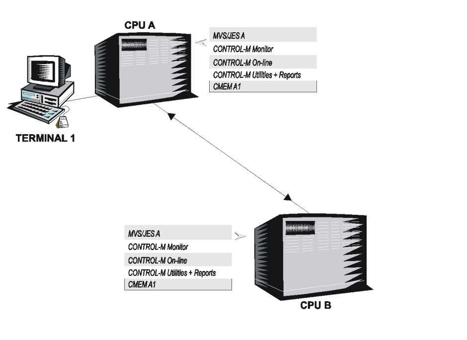
In this environment, the Control‑M system can
-
transfer data to the other system
-
transfer alerts to the other system
-
trigger events in the other system
-
schedule work in the other system
Control‑M can interact with various Network Management and File Transfer products that use existing connections between the z/OS platform and the other platform.
Network Management Products
Systems that are connected by Network Management products can use this connection to transfer triggers (events) from the Control‑M system to another SNA system.
Control‑M can schedule a dummy job that sends a SHOUT message to the system console. The message can be captured by NetView, which triggers a command that is transmitted by NetView to a remote VSE system console, or through a TAF terminal to a remote application such as IMS/DC or CICS.
File Transfer Products
Various File Transfer products can be used under MVS to transfer data from MVS to other systems, and vice versa.
These File Transfer programs include FTPSERV from IBM, and XCOM and CONNECT DIRECT (formerly NDM) from Computer Associates (CA). In addition, the TSO/E TRANSMIT and RECEIVE commands can be used to send and receive files.
Each product has its own transfer method and may or may not have easy-to-use interfaces and exits. We provide some general tips on how Control‑M can interface with these products. We recommend that you check with the appropriate software representative to determine whether these tips are suitable for your environment.
Tips for Interfacing with File Transfer Products
-
ControlM can periodically trigger a file transfer from the MVS system to the other system. This technique can be used to pass data to the other system. In some cases, the transferred data can trigger a process in the target system.
-
All File Transfer products can be interfaced using batch and/or TSO. ControlM can submit a job that interfaces with the File Transfer product by invoking the appropriate program under batch or by operating TSO Batch and invoking the File Transfer product’s TSO interface.
-
The CMEM facility can be used to acknowledge the receipt of a file from another system and, for instance, to order a job to handle that file (or add a prerequisite condition indicating that the file arrived). CMEM can only acknowledge the receipt of files under the following conditions:
-
The file is received by a started task (STC) or job. Most File Transfer products use an STC for this functions. However, TSO RECEIVE and TRANSMIT operate under TSO.
-
The File Transfer product uses regular MVS ALLOCATION/ DEALLOCATION facilities (that is, SVC 99) to create the new file.
-
CMEM can acknowledge the receipt of files. However, it cannot determine whether the file transfer process was successful or not.
If the File Transfer product provides appropriate exits, these exits can be used to inform Control‑M of events occurring within the File Transfer product.
For example, if the other system has a "File Receipt" exit, utility IOACND can be called by this exit to add a prerequisite condition that informs Control‑M that a file has been received.
Some products provide the option to submit a job after the file transfer process has finished. Such a job can invoke utility IOACND to add a prerequisite condition to the IOA Conditions file.
For information about the built-in Control‑M interface to CONNECT DIRECT, see CONNECT DIRECT Support (Formerly NDM Support).
Automatic Restart Management Support
Automatic restart management can reduce the impact of an unexpected error to a system program by restarting it automatically, without operator intervention. In a Sysplex environment, a system program can enhance its own recovery potential by registering as an element of the automatic restart management function of the cross system coupling facility (XCF).
To provide program recovery through automatic restart management, your installation must activate a policy through the SETXCF START command. This can be an installation-written policy or part of the IBM-supplied policy defaults. Because an installation-written policy may affect your program, you must understand how your installation uses automatic restart management for recovery in a Sysplex. Details of the automatic restart management function are described in the section of IBM manual MVS Programming: Sysplex Services Guide that discusses using the automatic restart management function of XCF.
In general, the operating system restarts an element under the following conditions:
-
when the element itself fails—in this case, the operating system restarts the element on the same system
-
when the system on which the element was running unexpectedly fails or leaves the Sysplex—in this case, the operating system restarts the element on another system in the Sysplex. This is called a cross-system restart.
The operating system will not attempt to restart an element if
-
the element has not yet registered as an element of automatic restart management
-
the element is cancelled through a CANCEL, STOP, or FORCE command (without the ARMRESTART parameter specified)
-
JES is down or has indicated that the element should not be restarted
-
the element has reached the restart attempts threshold specified in the policy
-
the policy indicates that this element should not to be restarted
-
access to the ARM couple data set was lost
Installing and Implementing Automatic Restart Management for Control-M
Automatic Restart Management and Control-M Failure
If ARM support is enabled and Control‑M fails unexpectedly, the following message is issued when the operating system automatically restarts Control‑M:
CTM181I AUTOMATIC RESTART IN PROGRESS AFTER UNEXPECTED FAILURERestart Parameters
There are several parameters you can choose to determine where, under what circumstances, and how many times, Control-M is to be restarted. Some of these restart parameters are described in the following table:
Table 120 Restart Parameters
|
Parameter |
Description |
|---|---|
|
TARGET_SYSTEM |
Systems on which Control-M can be restarted in a cross-system restart. |
|
ELEMENT |
Element name that represents Control-M. This must exactly match the ARMELMNT CTMPARM parameter. |
|
RESTART_ATTEMPTS |
Maximum number of times that the operating system should attempt to restart Control-M. This limit prevents the operating system from continually restarting an element that is recursively terminating. |
|
TERMTYPE |
Specifies under which condition the operating system should restart Control-M. Valid values are:
|
|
RESTART_METHOD |
Specifies the command text that the operating system is to use to restart the element. The statement RESTART_METHOD (BOTH,PERSIST) indicates that the operating system is to use the command text that previously started Control-M. When setting up an ARM policy, do not use this parameter. For more information on when to use this parameter, see Automatic Restart Management and Control-M Failure. |
To obtain information about elements of the automatic restart manager while the system is active, you can issue the D XCF,ARMSTATUS,DETAIL MVS operator command. For more information about this command, see the discussion about displaying cross system coupling facility (XCF) information, in the IBM manual MVS System Commands.
The following is an example of an addition to the existing automatic restart management policy of an installation. The example specifies a target system and directs that Control‑M should be restarted only if the system program terminates, but not when the system terminates.
RESTART_GROUP(CONTROLM)
  TARGET_SYSTEM(OS35)
  ELEMENT(CONTROLM*)
    TERMTYPE(ELEMTERM)
CTMPLEX: Control-M for the Sysplex
The CTMPLEX architecture in Control‑M is designed to work in a Parallel Sysplex environment with JES MAS (multi-access spool) configuration. It gives Control‑M multi-tasking capabilities across the Sysplex, supplies multi-CPU dynamic workload balancing capabilities, and provides a single Sysplex view of the entire production environment. The product offers a comprehensive production solution, enabling users to introduce Sysplex technologies into the business environment without risking the production throughput.
The scheduling benefits that are offered by Control‑M using CTMPLEX in a large Sysplex environment include the following:
-
large-scalability Sysplex scheduling support
-
enterprise-wide view
-
availability and recovery
-
more efficient workload balancing
Large-Scalability Parallel Sysplex Scheduling Support
CTMPLEX (the Control‑M Parallel Sysplex support configuration) provides users with management capabilities over the entire Sysplex environment.
When utilizing a small Sysplex environment (for example, up to five Sysplex images), a single Control‑M monitor can supports all CPUs, all controlled from a single tracking and control screen.
For large-scale Sysplex environments, CTMPLEX utilizes its advanced Sysplex management. The product activates a Control‑M Global Sysplex Manager (GSM) on one of the MVS images in the Sysplex environment. The system administrator can then select any or all of the remaining Sysplex images and activate Control‑M Local Sysplex Monitors (LSM) on those images. The Control‑M GSM has exclusive access to the Control‑M Repository (Active Jobs file, Resources file, and so on), and controls the workload balancing among all Control‑M LSMs. Each LSM receives portions of work from the GSM, performs the work and reports the results to the GSM.
This Parallel Sysplex Control‑M configuration allows the product to take advantage of all available resources in the Sysplex, such as CPUs, JES, and the Coupling facility, and to handle any number of jobs that may run in the Sysplex at any time. Each Control‑M’s LSM controls and monitors a portion of the active jobs that runs in the Sysplex. Consequently, the workload is divided among all available CPUs and JES components, preventing potential bottlenecks.
Enterprise-wide View
Although the GSM and the LSMs run on different Sysplex images, IOA screens provides a view of the entire enterprise, regardless of the system used to log onto the Sysplex. This cross-CPU viewing capability allows users to make all definitions (jobs, resources, and so on) in the same user interface and store them in a common database, regardless of the system on which the definitions actually take effect. Users are also given the power to track and control multiple systems and applications, regardless of the image on which the tasks are executed. A Control‑M user, for instance, can track and control production across the entire Sysplex by logging on from any system in the Sysplex, regardless of whether the Control‑M monitor is active on that system.
Availability and Recovery
When activating CTMPLEX, the product uses the Coupling Facility services for communication between the Control‑M's GSM and LSMs, assuring high speed and reliable information transfer between the GSM and all LSMs. The information exchange between Control‑M components can also be stored and maintained by the Coupling Facility itself for recoverability if Coupling Facility malfunction occurs.
Using the Coupling facility services, the Control‑M's GSM automatically detects all LSM or communication failures, assuring that all work associated with the problematic LSM are distributed among other available LSMs until the failure has been corrected. In case of a Control-M's GSM malfunction, the LSM with the highest PRIORITY value replaces the GSM instantaneously to assure an uninterrupted production operation in the Sysplex. When the original GSM restarts, it takes over the GSM function again, since it has the highest PRIORITY value, while the current GSM resumes its LSM role.
If PRIORITY values are changed during the execution of the monitors, the NEWPLEX modify command must be issued to ensure all monitors are working with the same CTMPLEX configuration, and to force the highest priority monitor to become the GSM. Stopping and starting monitors without the NEWPLEX command, may result in a situation where the monitor that is best suited to function as the GSM does not have the highest priority and therefore will only function as an LSM.
CTMPLEX's flexible design and effective operation allows the product to handle the entire Sysplex Batch workload 24x7, without requiring shutdown time for product maintenance. Information is not lost even if one of the Control‑M monitors or LPARS in the Sysplex is not available. The remaining Control‑M monitors automatically updates themselves with any changes that occurred while a Control‑M monitor is unavailable.
In the case of a failure of the Control‑M's GSM, none of the LSMs should be stopped. Just cancel the GSM. This will cause one of the LSMs to switch to GSM, which preserves the CF structure and the data (jobs updates) saved in the CF, and allows the new GSM to read data from the CF structure and perform the required AJF updates.
Glossary of CTMPLEX Terms
Table 121 Glossary of CTMPLEX Terms
|
Term |
Definition |
|---|---|
|
CTMPLEX |
Multiple Control‑M monitor configuration under an MVS Parallel Sysplex with a JES MAS (multi-access spool) environment. |
|
Control‑M Global Sysplex Manager (GSM) |
The GSM is the one (and only one) monitor that uniquely serves the entire Sysplex. Its main activities include: Select and post-processing phases (not including SYSOUT and DO SYSOUT operations); handling dummy jobs and SMART Table Entities; I/O against the main databases (AJF, CND and RES); processing external events (Hold, Free, Delete, and so on) and executing CMEM/Control‑O requests. |
|
Control‑M's Local Sysplex Monitor (LSM) |
The LSM is a Local monitor, started on any Sysplex member (but only one Control‑M monitor on each Sysplex member). This monitor performs the SUB (submitting) and SPY (follow-up on jobs, reading and analyzing of job SYSOUT) phases of each job, including the SYSOUT and DO SYSOUT functions of the post-processing phase. The first Control‑M monitor that is started in the Sysplex becomes the GSM. Every Control-M monitor started after that acts as an LSM, unless it has a higher PRIORITY, in which case it takes over the role of the GSM, while the first Control-M monitor becomes an LSM. This global monitor selection process continues, so that ultimately the Control-M monitor with the highest PRIORITY value functions as the GSM. Only one Control‑M monitor may run on each Sysplex member. |
|
Coupling Facility (CF) Usage |
The Coupling Facility list structure is used as common storage for the jobs, and as the method of communication between the GSM and LSMs. The Coupling Facility is mostly used to store active jobs ( jobs that passed the Select phase – and are Eligible for Run ‑ but have not ended yet). |
|
GSM |
See Control‑M Global Sysplex Manager. |
|
Global |
See Control‑M Global Sysplex Manager. |
|
LSM |
See Control‑M Local Sysplex Manager. |
|
Local |
See Control‑M Local Sysplex Manager. |
|
RAS |
CTMPLEX is designed to achieve continuous operation (24x7), enable the maintenance of the Sysplex without stopping Control‑M, and minimize the delay caused in cases where a monitor or CPU failure occurs. When the GSM unexpectedly terminates (either abended or its CPU terminates), one LSM (the first to detect GSM failure) switches itself to function as the GSM. When an LSM fails, the GSM takes responsibility over the work that was handled by the failing LSM, and passes it to another available LSM. When the Coupling Facility fails (or is not used), the GSM itself can continue working without the Coupling Facility and without the LSMs (as a regular Control‑M, not in CTMPLEX mode). |
|
Workload Balancing |
CTMPLEX is designed to work with or without Workload Balancing between Control‑M monitors. In a Workload Balancing mode, the GSM assigns work to LSMs according to a predefined capacity and the current utilization of each LSM (and the GSM itself), trying to make the utilization percentage equal on all Control‑M monitors. In non-Workload Balancing mode, each LSM "picks up" jobs for processing according to its availability. Initialization parameters and real-time Modify commands may enable or disable Workload Balancing mode and change the capacity for the Control‑M monitors on each Sysplex member. For each Sysplex member, a relative capacity (parameter RELCAP) and a maximum capacity (parameter MAXCAP) can be specified. RELCAP is used for calculating the utilization of members (for workload balancing). MAXCAP specifies the maximum number of jobs that can be processed by a Control‑M monitor (GSM or LSM) running on the corresponding member. Example: The administrator can give low priority to batch processing during the day shift by utilizing CPUA with no more than 50 jobs and CPUB with no more than 60 jobs. During the night shift, the administrator can give batch processing a higher priority by changing the number of jobs in both CPUs to 150 concurrent jobs. |
CTMPLEX Configuration Considerations
Although no special configuration requirements are necessary, the following points must be taken into consideration:
-
All MVS systems (on which ControlM's GSM and LSMs monitors can run) must be members of one Parallel Sysplex with a Shared Spool (either JES2 MAS complex or JES complex). The Coupling Facility structure used by CTMPLEX must be available to all such Sysplex members.
-
The corresponding JES subsystems must share the same spool and checkpoint datasets. This means that the spool must be a JES2 multiaccess spool (MAS) configuration or a JES3 complex.
-
The size of the Coupling Facility’s List Structure is calculated based on numbers supplied during installation. These numbers must be carefully evaluated to make the List Structure large enough to contain all active jobs at any time, but not to make it too large so that it adversely affects the operation of the Coupling Facility itself.
-
A global resource serialization product (GRS, MIM or an equivalent product) must be used in the complex. In a Parallel Sysplex environment, every Sysplex member must be in the same Global Resource Serialization complex, since CTMPLEX needs a Global Serialization of resources in the complex.
CTMPLEX Installation Considerations
CTMPLEX is activated by setting parameter CTMPLEX to Y in the member CTMPARM.
The member CTMPLEX specifies Control‑M Sysplex installation parameters. This parameter member contains global parameters for both the CTMPLEX and specific initialization parameters for every Sysplex member where the GSM or LSMs can run. For more information about this member, see the INCONTROL for z/OS Installation Guide: Installing.
The procedure used to start GSM and all LSMs must be the same under all Sysplex members, and DD statements DAPARM and STEPLIB must point to the exact same libraries.
Controlling CTMPLEX
GSM manages dialogs with the operator, and ensures synchronization between all monitors in CTMPLEX. Operator-modified commands must be issued to GSM only. GSM then passes relevant commands to all LSMs, saves the current working profile, and provides the profile to new LSMs.
Table 122 Operator Commands
|
Operator Command |
Description |
|---|---|
|
S CONTROLM |
Initially start the CONTROLM monitor on any system. The monitor becomes either a GSM or LSM monitor depending on whether there are other CONTROLM monitors of the same CTMPLEX. |
|
F CONTROLM |
Issue a command to Control‑M CTMPLEX. May be issued on the system where GSM runs. |
|
P CONTROLM |
Stop any LSM (when issued on the system where an LSM runs) or stop the entire CTMPLEX (when issued on the system where the GSM runs). |
|
P LOCAL |
Stop an LSM started by the S CONTROLM.LOCAL operator command. |
Table 123 Operator Command Options
|
Option |
Description |
|---|---|
|
BALANCE |
Activates or inactivates a Work Balancing mode, overriding the value of parameter BALANCEM (specified in the CTMPLEX initialization member). Valid values are: YES – Activate Work Balancing mode. NO – Deactivate Work Balancing mode. |
|
STOPPLEX |
Stops all LSM monitors. The GSM monitor continues working in regular (not CTMPLEX) mode. The stop operator command (P CONTROLM) issued for a GSM monitor stops all CONTROLM monitors of the corresponding environment. The stop command issued for an LSM stops that LSM only. |
|
STOPGSM |
Stops the GSM monitor. Valid values are: system_identifier – If a system identifier is specified, the LSM monitor of the corresponding system (Sysplex member) becomes the new GSM. ' ' (Blank) – If a system identifier is not specified, the first LSM that detects that the GSM has shut down becomes the new GSM. |
|
LISTPLEX |
Displays information about all monitors (GSM and LSMs) of the CTMPLEX. |
|
STARTPLEX |
Resumes CTMPLEX processing after environmental errors related to the CTMPLEX Coupling facility structure occur. After such errors, CTMPLEX stops all LSMs and the GLM continues working in standalone mode until the STARTPLEX command is issued. |
|
WHOGLOBAL |
Displays information about the GSM. This is the only CTMPLEX command valid for local monitors (LSMs). |
|
DUMPPLEX |
Issues a diagnostic dump (to any of SYS1.DUMPxx datasets) in order to obtain the contents of the CTMPLEX Coupling facility structure. |
|
NEWPLEX |
Enables dynamic refreshing of CTMPLEX parameters |
Automatic recovery of the CTMPLEX Facility after Coupling Facility failures
If automatic recovery of CTMPLEX is inactive, then in the case of Coupling Facility failures or other problems that prevent Control-M from working in CTMPLEX mode, the following occurs:
-
All Local monitors stop (either by themselves or according to a request from a Global monitor).
-
The Global monitor releases all CTMPLEX resources, disconnects from the Coupling Facility, and continues working as a regular CTM monitor. This is actually the same processing as one happens after STOPPLEX operator command.
To resume CTMPLEX processing (to return to CTMPLEX mode), the operator should issue the STARTPLEX operator command. As the result of this command, the Control-M monitor loads CTMPLEX resources and definitions, connects to the Coupling Facility, and becomes a Control-M Global monitor. After this, the operator may start Local monitors.
The CTMPLEX Automatic Recovery function automatically performs the actions mentioned above (reactivating CTMPLEX and restarting Local monitors), without any need for operator intervention. Automatic Recovery is controlled by the RECOVERT and RECOVERM CTMPLEX installation parameters.
When Automatic Recovery is activated (the RECOVERT installation parameter is not set to zero), in the case of Coupling Facility errors (or other failures preventing Control-M from using CTMPLEX), the Global monitor releases all CTMPLEX resources and continues working as a regular (standalone) Control-M monitor. Local monitors pause and wait for CTMPLEX to be reactivated.
From time to time, in accordance with the value of the RECOVERT installation parameter that defines the interval between attempts, the Global monitor tries to recover CTMPLEX. This means that the Global monitor tries to build a CTMPLEX environment, connect to Coupling Facility, allocate and populate new Coupling Facility structures, and so on. New Coupling Facility structures may be allocated in another Coupling Facility and have characteristics such as when the Global monitor uses the current CTMPLEX parameters member and active CFRM policies. The Global monitor may try several attempts to recover CTMPLEX. The maximum number of attempts is set by the RECOVERM installation parameter in the CTMPLEX parameters member.
If the Global monitor succeeds in recovering CTMPLEX, then the Global monitor frees Local monitors by sending them an order to resume operation). If the Global monitor does not successfully resume CTMPLEX within the maximum number of attempts allowed the RECOVERM installation parameter in the CTMPLEX parameters member), then it orders Local monitors to shut down.
Troubleshooting and Disaster Recovery Planning
Control-M Errors
If a critical internal error is detected in the Control‑M monitor, the monitor automatically shuts itself down and the following highlighted unrollable message is issued to the operator console:
CTM121S Control‑M MONITOR ENDED WITH ERRORIf there is an abend in one of the Control‑M monitor’s tasks, the monitor abends with user abend code U0006. If this occurs, contact the INCONTROL administrator. Always have a full dump of the original abend (not the U0006) available for analysis.
Problem Determination using the Internal Trace Facility
IOA provides an internal Trace facility that can print internal trace records and the contents of internal data areas. Under normal circumstances, the Trace facility is dormant. However, if required (that is, BMC Customer Support has requested trace information), the Trace facility can be activated.
To use the Control‑M internal Trace facility, issue the following operator command:
F CONTROLM,TRACE=levelwhere level indicates trace levels to be activated or deactivated. The Control‑M Trace facility has 128 levels (that is, from 1 through 128). Any number of these levels can be on at a given time. Valid values are
-
x – Trace level to turn on
Example: TRACE=3 turns on trace level 3. -
x – Trace level to turn off
Example: TRACE=3 turns off trace level 3. -
(x:y) – Range of trace levels to turn on, where x is the first level in the range and y is the last level in the range.
Example: TRACE=(1:10) turns on trace levels 1 through 10. -
(x:y) – Range of trace levels to turn off, where x is the first level in the range and y is the last level in the range.
Example: TRACE=(1:10) turns off trace levels 1 through 10. -
(x,y,z,...) – Multiple trace levels to turn on.
Example: TRACE=(3,5,29) turns on trace levels 3, 5 and 29. -
(x,y,z,...) – Multiple trace levels to turn off.
Example: TRACE=(3,5,29) turns off trace levels 3, 5 and 29. -
SHOW – Shows the current status of all trace levels.
Depending on which trace levels were turned on, trace information is written to one or more of the following locations:
-
DD statement DATRACE of the ControlM procedure
-
DD statement DADUMP of the ControlM procedure.
-
SYSDATA of the ControlM started task
When you finish performing the problem determination procedures, use the following operator command to turn off all trace levels:
F CONTROLM,TRACE=(-1:-128)Control‑M performance trace data can also be accumulated and processed in conjunction with the IOA Internal Trace facility. For more information, see Chapter 2, "IOA Administration."
Capturing first failure data using In-Memory Buffer Trace
For Control‑M the IOA Internal Tracing facility supports an additional option for tracing into memory buffers. Tracing into memory buffers makes the most relevant data available the moment a problem first arises. The trace data is written into a buffer that wraps around to the beginning when the end of the buffer is reached. The content of the buffer is available in dumps or by manually flushing it to an output file when required. For more information on the Internal Tracing facility, see Chapter 2, "IOA Administration."
The Control‑M RELOAD and FLUSH modify commands for the In-Memory Buffer Trace feature are available to the Control-M Monitor and Application Server.
Use the following command to refresh the trace facility parameters from the DATRCIN and DATRCBF files:
F <monitor>,TRACE=RELOADUse the following command to write the contents of a memory buffer to the DD statement DATRACE file:
F <monitor>,TRACE=FLUSH,BUFID=ALLUse the FLUSH command whenever the operator determines irregular behavior of the product.
Determining the Control-M Trace Level Intensity Preference
The user has the option to choose the intensity level of the traces produced by the Control-M Trace Facility. For the Control-M monitor and Newday process the intensity level is determined by choosing one of the following members located in the CTM PARM library:
-
CTMTRCML contains the Low trace intensity levels with an allocated buffer size of 300,000 lines
-
CTMTRCMM contains the Medium trace intensity levels with an allocated buffer size of 900,000 lines
-
CTMTRCMH contains the High trace intensity levels with an allocated buffer size of 1,500,000 lines
Each of the members listed above contain the same trace level. They differ only in the size of the buffer allocated.
For the Control-M Application Server the intensity level is determined by choosing one of the following members located in the CTM PARM library:
-
CTMTRCAL contains the Low trace intensity levels
-
CTMTRCAM contains the Medium trace intensity levels
-
CTMTRCAH contains the High trace intensity levels
Control‑M uses the MTRC parameter in the Control‑M monitor, Newday process and Application Server JCL procedures to determine which trace intensity level member to use. The user can specify the trace intensity level by setting the MTRC parameter to one of the following values:
-
L - Low trace intensity level
-
M - Medium trace intensity level (Default)
-
H - High trace intensity level
Control-M Health Checker interface
The Control‑M Health Checker interface is an additional tool that you can use in troubleshooting problems in Control‑M. For an overview of the Control‑M Health Checker interface, see the Control‑M for z/OS User Guide. For details on implementing this interface, see the INCONTROL for z/OS Installation Guide: Customizing.
Performance data collection
The Control-M monitor accumulates performance data which is used to produce SMF records. These records are written out to SMF at given time intervals (controlled by the PFMINT parameter in the CTMPARM member of the IOA PARM library), or in response to the operator command PERFDATA. The writing of the SMF records is accompanied by corresponding messages in the Trace file.
Understanding the performance data record
The monitor writes performance records for each relevant function. Functions may be job specific (such as the reading of one particular job's output), or can relate to an entire cycle (such as one cycle of CTMSEL).
The following table describes the structure of the performance record written to SMF. The structure of the IOA log messages, issued along with the SMF records, is similar but has meaningful text values substituted for task-name and function-name.
Table 124 Structure of performance record
|
Field |
Comments |
|---|---|
|
task-name |
Identifies the application for which performance data is being accumulated. See the following table for a list of possible task names and their associated functions: |
|
start-date-accumulation |
|
|
start-time-accumulation |
|
|
The following fields provide function level details and are repeated (as a unit) as many times as needed, depending on the number of functions being traced for the task. |
|
|
function-name |
Identifies the process within the task for which the performance data was accumulated. See the following table for a list of possible task names and their associated functions. |
|
number-of-times-called |
|
|
total-elapse-time |
|
|
total-cpu-time |
|
|
average-elapse-time |
|
|
average-cpu-time |
|
|
maximum-elapse-time |
|
|
maximum-cpu-time |
|
|
func-related-# |
|
|
func-related-avg# |
|
The following example shows a performance record:
<task-name, start-date-accumulation, start-time-accumulation,
[function-name, number-of-times- called, total-elapse-time,
total-cpu-time, average-elapse-time, average-cpu-time,
maximum-elapse-time, maximum-cpu-time, func-related-#, func-related-avg#] […]>
The following table shows a list of possible task names and their associated functions:
Table 125 Performance data accumulation tasks and associated functions
|
Task |
Description |
Functions |
|---|---|---|
|
CTMRUN |
Control‑M monitor |
RUN CKP PLX OPR |
|
CTMSEL |
Selection processing |
SEL WCN X15 CND SHT CNU PRE POS |
|
CTMSUB |
Submitter processing |
SUB MEM JSP X02 SE2 JES ERQ STC ALC |
|
CTMSPY |
Output processing |
SPY STA PSO SDB COP EX2 |
|
CTWSRVR, CTWSRUS |
Control‑M application server |
SRV XDS DWN SNC USR INF UPL DFD DFU ORD |
|
CTWDET |
Control‑M application server (detector) |
DET AJU AJN CND RES ALR AJ0 |
|
CTMFRM, CTMJOB |
AJF formatting and Job Ordering processing |
REA PHS PAR GRP FRS RS0 WRI JOB RET SEC TAP IGN INP |
|
CTMJOB |
Job Ordering processing |
JOB RET SEC TAP IGN |
BMC may modify the list of tasks and associated function names as the needs arise.
Collecting performance data
The profiler is called at the start (before) and end (after) of a function. The following information is passed to the profiler each time it is called.
-
task identifier (task-name)
-
function identifier (function-name)
-
processing unit identifier (processing-unit-id)
-
before/after indicator
When the profiler is called at the end (after) of the function the program performs the following actions:
-
calculates the statistical data
-
adds the data to the accumulated statistic record
-
edits the data based on the trace level specified
-
writes a readable performance record (or keeps it in memory).
For all record types, the data will be included in the performance record if the time is equal or greater than 0.01 sec.
Writing performance records
Performance records are accumulated at given time intervals controlled by the PFMINT parameter. (For more information, see the INCONTROL for z/OS Installation Guide: Customizing). At each interval the following process occurs:
-
the accumulated records are written to SMF
-
the records used to accumulate the data are cleared
-
accumulation process starts again with the cleared records
You can use the PERFDATA Control-M modify command, at any time, to write the accumulated data to SMF records. The PERFDATA command triggers the same process as above. Messages generated by the PERFDATA command are directed to the console issuing the command. For more information, see Accumulating performance data.
By setting a trace level it is also possible to specify that performance records be written to the system log as they are being accumulated. For each component of the Control‑M monitor there are specific trace levels and error messages which cause the performance records written by that component to be written immediately.
Customizing the collection of measurements for Control-M Configuration Manager
For instructions of how to generate a usage measurement report for Control-M for z/OS, see Control-M diagnostics > Generating diagnostic data in the Control-M Administrator Guide.
Beginning with z/OS® V1R12|(and z/OS V1R11 and z/OS V1R10 with the PTFs for APAR|OA29894 applied), the system administrator must register the CTWRSMF program (supplied by BMC, in the LOAD library, for use as a user exit for IFASMFDP) on the system according the IBM instructions described at the following location:
http://publib.boulder.ibm.com/infocenter/zos/v1r12/index.jsp?topic=%2Fcom.ibm.zos.r12.e0zm100%2Fifasmf1.htm
A job skeleton is provided in the CTMJSMF member of the CTM JCL library.
The usage measurements are stored in a file, allocated by the DACSV DD statement. The user can change any of the parameters in this DD statement, including the dataset name (DSN). To make sure that the names for new datasets are unique, use the special %%DATE and %%TIME parameters (reserved for DACSV dataset names), where %%DATE specifies the current date and %%TIME specifies the current time.
For example, the original dataset name is as follows:
%OLPREFM%.CSV.D%%Date.T%%Timewhere %%OLPREFM%% is the prefix library.
There is no need to define input datasets for the job, since by default all active system SMF datasets are being used as input. To increase the time period for data retrieval, any number of archived SMF datasets can be added to the job skeleton. The user can include additional archived SMF files by adding a separate DD statement for each SMF file as follows:
//ddname_1 DD DISP=SHR, DSN=dataset_name_1
//ddname_2 DD DISP=SHR, DSN=dataset_name_2
To process these additional archived datasets, the corresponding input (SYSIN) statements must be added to the job skeleton as follows:
INDD(DDNAME_1, OPTIONS(DUMP))
INDD(DDNAME_2, OPTIONS(DUMP))
Disaster Recovery Overview
This topic describes disaster recovery tasks that must be performed in advance. If necessary, one can plan to activate the Control‑M monitor on a different computer system in the same data center (multi-CPU sites) or at a backup site.
Prepare the disaster recovery plan (a set of documented steps and procedures to implement in a specific order when the need arises) in advance. The documentation and software that form the disaster recovery plan must always be available so that the plan can be implemented quickly and easily. All of the topics discussed below must be considered.
Recovery Tools
The following tools, if properly implemented in advance, can be used for disaster recovery.
Dual Checkpoint Mode
The Control‑M monitor can work in dual checkpoint mode. Under this mode, the Control‑M monitor maintains duplicate copies (mirror files) of the Control‑M Active Jobs file (CKP) and the IOA Conditions file (CND). If a disk crash makes the primary files inaccessible, they can be restored from the mirror files.
For reasons of physical safety, both the mirror CKP and the CND must be placed on a different disk than the other Control‑M files. No dual checkpoint mode is available for the Control‑M Resources file (RES).
WARNING: Because of performance considerations, BMC no longer recommends using the mirror file mechanism. Instead—for backup and recovery—use the Control-M Journaling facility, described in Journaling. By using Journaling, you can avoid the performance loss associated with mirroring, taking advantage of the increased efficiency and integrity features built into modern storage devices.
The installation procedure for dual checkpoint mode is described in the explanation of ICE Step 4.2, "IOA Operational Parameters," and ICE Step 7, "Set Global Variables Database," in the IOA chapter of the INCONTROL for z/OS Installation Guide: Installing, and in the explanation of ICE Step 2, "Specify Control‑M Parameters," and ICE Step 3.1, "Control‑M Libraries and Repository," in the Control‑M chapter of the same guide.
When working in dual checkpointing mode, the Control‑M monitor keeps the Active Jobs mirror file synchronized with the primary Active Jobs file. The mirror file must be protected from any update by another source. If either the primary or mirror file becomes damaged, the Control‑M monitor shuts down with an appropriate message. To resume Control‑M monitor operation, the damaged file must be restored.
The Autoswitch feature can be enabled. If Dual Checkpointing is active, and the primary Active Jobs file undergoes hardware and software problems (in other words, is damaged), Control‑M automatically switches to dual. A message is issued, indicating that
-
you are working now in dual (this message is unrollable)
-
processing continues in both files
Restoring the Active Jobs file
To restore the Active Jobs file, perform the following steps:
-
Allocate and format a new Active Jobs file using utility FORMCKP.
-
Run utility CTMCAJF. Use the undamaged (dual) Active Jobs file as input and the newly created Active Jobs file as output.
-
Rename the damaged file. Then rename the newly created Active Jobs file with the original name of the damaged primary or mirror file.
-
Restart the ControlM monitor.
Restoring the IOA Conditions file
To restore the IOA Conditions file, perform the following steps:
-
Allocate and format a new IOA Conditions file using utility FORMCND. For information about the structure and space requirements of the IOA Conditions file, see the section that discusses the structure of the IOA Conditions File in the INCONTROL for z/OS Installation Guide: Installing.
-
Run member IOACCND in the IOA JCL library. Use the undamaged Conditions files as input and the newly created Conditions files as output.
-
Rename the damaged file. Then rename the newly-created file (CND) with the original name of the damaged primary or mirror file.
-
Restart the ControlM monitor.
Journaling
Journaling is an optional feature that can be implemented by the INCONTROL administrator. If implemented, the Control‑M Journal file collects data about changes occurring in the Control‑M Active Jobs file, the IOA Conditions file and the Control‑M Resources file during the Control‑M working day. If the Control‑M Active Jobs file, the IOA Conditions file (optionally) and the Control‑M Resources file (optionally) need to be restored (for example, following a system crash), utility CTMRSTR can be run to restore the files (from the data in the Journal file) to the status they were in as of any specific time after the last run of the New Day procedure.
If Control‑M installation parameter JRNL is set to Y (Yes), changes made to the Active Jobs file and prerequisite conditions added or deleted in the IOA Conditions file are recorded in the Journal file. If the Active Jobs file and/or IOA Conditions file must be restored, the Journal file can be used to implement the restoration.
Journal File Initialization
Journal file initialization is performed by the Control‑M monitor as part of New Day processing after the Newday procedure has completed OK. Initialization consists of the following steps:
-
Journal file initialization - All previous data in the Journal file is deleted. The file is initialized with date information that establishes synchronization with the Active Jobs file.
-
Active Jobs file snapshot - A snapshot of the Active Jobs file is taken. If the Active Jobs file must be restored, this snapshot file serves as the base file upon which restoration is performed.
-
IOA Conditions file snapshot - A snapshot of the prerequisite conditions in the IOA Conditions file is taken. If the IOA Conditions file must be restored, this snapshot file serves as the base file upon which restoration is performed.
Journal File Commands
Journal file activity is controlled by issuing modify commands to the Control‑M monitor. The following modify commands are available:
F CONTROLM,JOURNAL=ENABLEThis command initializes journaling. The steps described Journal File Initialization are performed, after which any changes made to the Active Jobs file and to prerequisite conditions in the IOA Conditions file are recorded in the Journal file.
F CONTROLM,JOURNAL=DISABLEThis command stops journaling. The Control‑M monitor continues normal processing without recording any changes in the Journal file.
Restoration
Utility CTMRSTR is used to restore the Active Jobs file and, optionally, prerequisite conditions in the IOA Conditions file. This utility is documented in the INCONTROL for z/OS Utilities Guide. When running this utility, consider the following:
-
The ControlM monitor and the ControlM Application Server (CTMAS) must be shut down when running utility CTMRSTR. If parameter CONDITIONS NO is specified in the utility job stream, ControlD and ControlO is not affected. If parameter CONDITIONS YES is specified, the operation of ControlD and ControlO can be affected by changes to prerequisite conditions in the IOA Conditions file.
-
ControlM and the ControlM Application Server (CTMAS) must be activated after restoration. Other INCONTROL products need not be recycled.
-
The ALTCKP file is fully updated when the Control-M monitor is initialized. Therefore, no special handling is needed for the restored Active Jobs file.
-
If parameter ENDTIME specifies a date or time that is earlier than the timestamp on the last entry of the Journal file, not all entries in the Journal file are restored. When the monitor is activated with the restored Active Jobs file, the following message are issued with a reply request:
CTML14E JOURNAL FILE IS NOT SYNCHRONIZED WITH NEWDAY PROCESSINGThe following replies are possible:
-
C – Continue without journaling. The ControlM monitor continues normal execution without updating the Journal file. This option can be used to ensure that ControlM is running properly after restoration. If necessary, ControlM can be shut down to perform restoration again. If no problems are encountered after restoration, the command JOURNAL=ENABLE can be used to reactivate journaling.
-
I – Initialize the Journal file. journaling is activated immediately after initialization and synchronization with the Active Jobs file. All data used to restore the Active Jobs file is deleted.
-
E – Shut down the ControlM monitor. The Journal file is not initialized.
The Control-M Recovery Facility
Whenever the Control-M monitor terminates, regardless whether the termination is normal or abnormal, Control-M performs a synchronization of the job data in memory with the disk copy kept in the CKP file. However, in rare cases where Control-M is unable to perform the synchronization, some of the jobs might remain in the CKP file in an ambiguous status. When Control-M is restarted, these jobs must be analyzed to clarify their actual status. In a CTMPLEX environment, a similar result might occur whenever a monitor (whether Global or Local) terminates abnormally or when there is a Coupling Facility failure (where the Local monitor activities cannot be passed to the Global monitor and saved in the Active Jobs File).
When Control-M detects an abnormal Control-M monitor termination, which prevents job information synchronization, or a similar situation in a CTMPLEX environment, Control-M automatically goes into "Recovery Mode." In this mode, Control-M extracts information about the jobs from the IOA LOG to determine the exact status of the jobs.
If the job status can be determined from the IOA LOG, the Control-M Recovery Mode processing sets the appropriate status. When Control-M restarts, the job processing continues without any need for manual intervention.
If the job status cannot be determined from the IOA LOG, to avoid the possibility of a duplicate submission or a DO FORCEJOB execution, the Control-M Recovery Mode processing puts the job into HOLD status and issues an appropriate message (see messages CTM5B3W and CTM5B4W in the INCONTROL for z/OS Messages Manual). These actions give the customer the opportunity to clarify the status of each of the jobs and perform the appropriate actions manually.
The installation parameters that control the Control-M Recovery Mode processing are located in the RECOVERY section of the CTMPARM parameters member. For more information about the parameters, see the RECOVERY section in Chapter 2, Customizing Control-M, in the INCONTROL for z/OS Installation Guide: Customizing.
Planning and Creating a Disaster Recovery Plan
Safeguarding MVS, JES, Exits and Other Definitions
Any defined links (such as exits) between MVS, JES (or any other software product or application), and Control‑M, must be documented, backed up, and defined in the disaster recovery plan.
Adding the Control‑M LOAD library to the LLA facility.
-
authorizing the LOAD library
-
changes to MVS exits
-
changes to JES parameters and exits
-
TSO Logon procedures and authorizations
Security Considerations
All security parameters must be backed up in such a way that they can be installed in the backup computer as a whole, not as a special "patch" installation.
Pay special attention to the following points:
-
The correct implementation of the security authorizations needed by the ControlM monitor (that is, defining the ControlM monitor and its special authorization to the security package used in the backup computer).
-
All security parameters and definitions must be backed up and copied to the backup computer.
-
Third-party vendor exits relating to ControlM (for example, RACF exit for R1.7 and R1.8—see the RACF Security Guide) must be copied, installed and checked in the backup computer, thus enabling a quick and correct implementation if the need arises.
-
ControlM security exits, if used, must be checked and passed as a part of the disaster recovery plan.
Scheduling Libraries and Other Production Libraries
Back up the following datasets at regular intervals, so that they are available if needed:
-
ControlM scheduling libraries
-
production JCL libraries
-
production parameters libraries
-
production symbols libraries
These libraries, used by Control‑M, must be backed up together. Perform this backup just after the New Day procedure has ended OK.
This backup is important because it reflects a picture of the production environment just before production begins. If a production application must be run again (for example, because a programming error entered corrupt data in the database) the backup can be used to reconstruct the environment.
An alternative solution is to utilize the History Jobs file. During New Day processing, jobs that ended OK or expired (according to job scheduling definition parameters) are deleted from the Active Jobs file. If these jobs are placed in the History Jobs file during New Day processing, they can be easily restored (by request) to the Active Jobs file for subsequent restart.
Backup Procedures
Control‑M files and appropriate production libraries must be backed up periodically. It is recommended that this backup be made just before batch processing begins. The backup frequency depends on your site’s requirements.
The New Day procedure creates a backup of the Active Jobs file before it begins deleting "yesterday’s" jobs. The backup (DSN suffix "BKP") must reside on a different disk than the Active Jobs file. This standard backup enables the internal recovery of the New Day procedure in case of cancellation, abends, system crash, or similar events.
The Active Jobs file, the Control‑M Resources file (RES), and the IOA Conditions file (CND), do not require special utilities for backup and can therefore be included in the standard site disk backup and maintenance procedures.
Control-M Parameter Definitions
The Control‑M installation procedure, parameters, and exits must be tailored to the backup computer. The Control‑M production control system must be installed and checked.
-
Contro-lM installation parameters (for example, HLDCLAS, INTERVLM, QNAME, SHRQNAM, ARCUNIT) may change, depending on the backup computer. For details, see the installation steps in the ControlM chapter of the INCONTROL for z/OS Installation Guide: Installing.
-
The mode of operation may differ (Dual Checkpoint mode or regular mode). For details, see the installation steps in the IOA chapter of the INCONTROL for z/OS Installation Guide: Installing.
-
Installation parameter CPUS must be adjusted to the backup computer. For details, see the installation steps in the IOA chapter and ControlM chapter of the INCONTROL for z/OS Installation Guide: Installing.
Take a close look at the installation procedure. Appropriate adjustments must be documented in the disaster recovery plan.
Catalog Considerations
Use a shared catalog when working in a multi-CPU environment. In case of a computer crash, all the relevant files remain cataloged in the backup computer. If any files are not cataloged in the shared catalog, they must be cataloged in advance in the backup computer.
Defining an Authorized TSO User
Define a special TSO user as part of the disaster recovery plan. Give this user the same security authorizations as the Control‑M monitor.
-
Ability to access all production JCLs, parameters and AutoEdit Facility symbol libraries (in read mode).
-
Ability to issue the TSO submit command from this special TSO user.
-
Authorization to submit jobs on behalf of other users. This authorization must enable the special TSO user to submit jobs as if they were submitted by ControlM.
Problem Resolutions
Various types of problems can occur in the Control‑M environment. Examples include
-
system crash (software and hardware)
-
ControlM abends
-
disaster recovery relocation
-
system maintenance (for example, installing a new version of z/OS)
Recommended solutions are presented for each of these problems.
Control-M Structural Recoverability
The Control‑M production control system must never be down. The Control‑M monitor, Online facility, ISPF utilities, Key-Stroke Language (KSL) and batch utilities are separate components. Most of them continue working even if other components are inoperable.
System Crash Auto Recovery Options
The Control‑M LOAD library, Core, and Repository (that is, Active Jobs file CKP, Conditions file CND, Control‑M Resources file RES, History Jobs file, and IOA Log file) must be restored to activate the Control‑M monitor in the backup site or the original site.
Once the monitor is active, it checks the JES queues and the Active Jobs file. The status of active jobs that are not on the JES queues change to "JOB DISAPPEARED". Other jobs are tracked, scanned or submitted when they are eligible.
Automatic handling of a system crash is illustrated in Automatic Recovery after a System Crash.
System Crash
The Control‑M monitor is usually started automatically as part of the IPL procedure. If any Control‑M files are inaccessible, the monitor shuts down with an appropriate message.
Because the Control‑M monitor is usually already active, it resumes production processing automatically.
Control-M Files are inaccessible
Disaster recovery from file inaccessibility (for example, file deleted by mistake, disk crash, and so on) is generally an easy task. Journaling, as well as appropriate backup and recovery procedures, provide a good solution to this recovery problem. For more information, see Recovery Tools.
IOA Log file is inaccessible
Define a new IOA Log file using utility CTMFRLOG. Then activate the Control‑M monitor.
Active Jobs file or IOA Conditions file is inaccessible – Non-dual mode
The status of the production environment can be determined according to the IOA Log file or the Active Jobs file (depending on which file is inaccessible). The recovery process is done manually, using reports extracted by specially designed programs and KSL.
In either case, whether running in dual mode or not, it is advisable to use the journaling and Restoration facility.
The Journal file is used to collect data relating to changes occurring in the Control‑M Active Jobs file and the IOA Conditions file during the Control‑M working day.
The Journal file is initialized each day during New Day processing. From that point on, for the rest of the working day, the Control‑M monitor records in the Journal file all activities that impact the Active Jobs file and all prerequisite condition changes.
If the Active Jobs file and (optionally) the IOA Conditions file need to be restored, run utility CTMRSTR to restore the files to the status they had as of any specific time after the last run of the New Day procedure.
AutoEdit Simulation Facility
In general, do not stop production processing even if the Control‑M monitor cannot be activated (for example, if the Control‑M Active Jobs file was deleted or a programming error occurred in one of the Control‑M exits).
The SUBMIT option of the AutoEdit Simulation facility can be used to enable submission of production jobs using the authorized TSO user. For additional information see Defining an Authorized TSO User.
You can determines what must be executed or submitted, and in what order, by using specially designed programs and KSLs. For more information on this topic, see Manual Recovery Procedures.
The AutoEdit Simulation facility simulates a Control‑M monitor submission (that is, it activates the Control‑M submission exit (Exit 2) and the AutoEdit facility). As a result no modifications to the JCL libraries are needed when submission is done through this facility.
The submission exit (Exit 2) can be used to check security authorizations. If security considerations for the recovery process are different, use an alternate submission exit.
JCL members that have AutoEdit facility statements before the JOB statement may cause the submission of a dummy job.
Control-M Monitor Abends
If the Control‑M monitor abends, it may be possible to determine that a specific job or started task caused the abend, as follows:
-
Examine any error messages that are displayed on the MVS Syslog screen.
-
Scan the bottom of the ControlM log for the last jobs handled by ControlM. The last jobs handled probably caused the abend.
If this is the case, change the status of the specific job or started task to HELD using the Control‑M Active Environment screen. When the monitor is reactivated, it processes the held request first and thus enables continuation of production work. (Control‑M bypasses all jobs in HELD status.)
To automate this process of Control-M monitor abend recovery for future occurrences, set the MAXJBHLD parameter in member CTMPARM of the IOA PARM library. For more information, see the INCONTROL for z/OS Installation Guide: Customizing, "Customizing INCONTROL products" > "Control-M customization considerations."
If the Control‑M monitor cannot be reactivated, continue to work manually, as explained in AutoEdit Simulation Facility
For more information about implementing the submission work plan, see Manual Recovery Procedures.
Disaster Relocation
Shared DASD (Multi-CPU Environment)
Starting a Control‑M monitor in the second CPU should not be a problem, because all production files (that is, the Control‑M LOAD library, the Repository, the production JCL parameters, and the symbols libraries) are cataloged and reside on shared DASD. For more information, see Control-M Parameter Definitions.
Backup Site
Use the disaster recovery plan. Transfer Control‑M and the production files from the most recent backups. Install and activate Control‑M. Resume production work using manual recovery procedures and these backups. For more information, see Manual Recovery Procedures.
System Maintenance
System maintenance usually does not affect Control‑M. After system maintenance ends, activate the Control‑M monitor and resume production. However, when making a major change or upgrade to MVS or JES, it is recommended that you test the production environment before performing the upgrade.
If the MVS SPOOL is to be changed or reformatted during system maintenance, perform the following steps:
-
Shut down the ControlM monitor.
-
Unload the content of the SPOOL to tape or disk
Before production resumes, perform the following steps:
-
Reload the SPOOL.
-
Reactivate the ControlM monitor.
If the SMF-ID or the JES-ID are changed, see the INCONTROL for z/OS Installation Guide: Installing > "Installation considerations" > "Adding, deleting and/or changing an SMFID in the computer list."
Manual Recovery Procedures
Manual recovery can be performed by using the IOA Log file or the Control‑M Active Jobs file (depending on the file that is accessible).
The relevant KSL scripts in the IOA SAMPLE library can be tailored as necessary.
CTMRFLW and CTMRNSC Reports
If the Control‑M monitor cannot be activated or the Active Jobs file is inaccessible, use the CTMRFLW and CTMRNSC reports to determine which jobs to submit, and in what order.
Job flow report CTMRFLW provides information about jobs in the Active Jobs file sorted by SMART Tables. For each SMART Table, the jobs are presented in order of expected execution. Generate this report daily, before starting the batch production cycle. It can be used if the Active Jobs file is lost during the batch production cycle.
The night schedule report (CTMRNSC) provides a summary of all jobs that executed during a specified time range. The start-time, end-time, elapsed time, and other data are reported for each job. Sort the report by SMART Table, end-time and start-time (parameter "TABLE ENDTIME").
By combining these two reports (manually or by a user-written program), the exact status of the production environment can be established. Sorting the reports by SMART Tables, which usually represent application systems, makes it easy for production personnel to continue the work manually (by SMART Tables, using the AutoEdit Simulation facility SUBMIT option).
KSL Log Reports
REP5ALL activates KSL program REPLOGAL. This program prints all the log messages for a specified date. The report’s output indicates which jobs did not yet execute.
The following code shows an example of a KSL Log Report:
//STEP1 EXEC CTMRKSL
TRACE OFF
MAXCOMMAND999999
CALLMEM  REPLGMSG  FROMDATE  TODATE   JOB511I NULL  NULL  NULL
END
//STEP2 EXEC CTMRKSL
TRACE OFF
MAXCOMMAND999999
CALLMEM  REPLGMSG  FROMDATE  TODATE   CTM659I FRM467I SEL208I  NULL
END
REP5MSGD activates KSL program REPLGMSG. This program prints only relevant log messages for a specific time span. A maximum of four messages can be specified as input parameters. This report must be generate in two steps.
In the STEP1 and STEP2 set the following parameters:
-
FROMDATE – Date from which data is extracted, in format (ddmmyy or mmddyy) used at your site.
-
TODATE – Date to which data is still relevant, in format (ddmmyy or mmddyy) used at your site.
The most practical value for parameter FROM DATE depends on the value of parameter MAXWAIT (for example, if most production jobs do not have a MAXWAIT parameter of more than seven days, parameter FROMDATE must not exceed seven days),
STEP1 prints a list of all the jobs placed on the Active Jobs file (message: JOB511).
STEP2 prints a list of all the jobs that ended OK, were discarded (MAXWAIT exceeded), were held, or were deleted by online users.
By manually combining these two reports, an accurate list of all jobs that must be scheduled and executed can be compiled. This method is complex, error prone, and does not determine the exact order of scheduling.Use this method only if there is no alternative (that is, no other way exists to restore the Active Jobs file).
REP5EXP activates KSL program REPLOGEX. This program can help trace problematic jobs (for example, jobs ending in abends, and so on). Priorities can then be better defined and reasonable throughput maintained.
Using the Active Jobs File
REP3ALLJ activates KSL program REPJOBST. This program prints a list of the Active Jobs file. It can be used as a general guideline to the planned recovery procedure.
REP3LEFT activates KSL program REPJOBMO. This program prints a list of all jobs in active and problematic status:
1.  WAIT SCHEDULE    7.  RECOVERY NEEDED
2.  WAIT SUBMISSION  8.  DISAPPEARED
3.  SUBMITTED        9.  ABENDED
4.  WAIT EXECUTION   10. UNEXPECTED CC
5.  EXECUTING        11. JCL ERROR
6.  ENDED NOT OK
Using this report in combination with the state of the jobs in the JES queues (statuses 2 through 5), a manual submission work plan can be devised. This work plan can be executed using the AutoEdit Simulation facility SUBMIT command.
Automatic Recovery after a System Crash
The following example illustrates an automatic recovery process defined to a job to be used after a system crash. This example uses value *UKNW in the CODES parameter.
This example assumes that there was a computer crash during the execution of this job. When the Control‑M monitor is activated, the recovery program is submitted and a message are sent to the appropriate user.
 ON PGMSTEP ANYSTEP   PROCSTEP         CODES *UKNW
 DO COND RESTART-AP-STC                   ODAT +
 DO SHOUT                      TO TSO-AP1 URGENCY U
MSG SYSTEM CRASH – AUTO TO FILE RECOVERY IS ACTIVE Communities
 Support Center
 YouTube
 Twitter
 Facebook
 LinkedIn