Overview
This chapter describes the customization facilities available within IOA, including:
-
IOA Online Environment
-
Destination Tables
-
Expanding IOA Files
-
Problem Determination
-
TSO/ISPF
IOA Online Environment
The Online facility can be activated under, and supply services to, the following environments:
-
TSO (native)
-
VTAM
-
TSO/ISPF
-
IMS/DC
-
ROSCOE/ETSO
-
IDMS/DC
-
CICS
-
COM-PLETE
Options for cross‑memory interfaces to the Online monitor address space are available under native TSO and ROSCOE/ETSO.
There are slight differences in the operation of the Online facility under different environments.
The following topics describe how the IOA Online monitor facility provides support for various environments using CICS as a model scenario. The description also applies to the following environments:
-
IMS/DC
-
VTAM
-
COMPLETE
-
IDMS/DC
-
ROSCOE CrossMemory Interface
-
TSO CrossMemory Interface
Entering the IOA Online Facility
In TSO and ISPF, the IOA Online facility is entered by running a CLIST (located in the IOA CLIST library). The CLIST calls IOAONL, which is the main CLIST that activates the Online facility in the specified environment.
The following CLISTs are provided for activating the IOA Online facility in the indicated environment:
Table 8 CLISTs for Activating the IOA Online Facility
|
CLIST |
Environment |
|---|---|
|
IOATSO |
TSO environment. |
|
IOAISPF |
ISPF environment. |
|
IOAXTSO |
TSO through Cross‑Memory services. |
The CLIST format used to activate the IOA Online environment under ISPF or TSO is:
IOAONL APPLTYPE(atype) [TRANID(transmem)]-
atype is the type of environment under which IOA is run. Valid values are I (ISPF), S (TSO) and X (Online monitor).
-
transmem is the name of the relevant transaction member in the IOA PARM library. Maximum length: four characters. Optional.
If no transaction member is specified, a full list of all options for the installed products is displayed.
For more information see Transaction Members.
At a site where Control‑M and Control‑D are installed, the following CLIST enables all options for Control‑M and Control‑D under TSO:
%IOAONL APPLTYPESDataset allocation for the IOA Online environment can be customized using specification of overriding or alternative Allocation members in the CLIST used to activate the IOA Online environment. For more information, see Allocation Members.
You can pass a transaction ID directly as a keyword parameter to either the IOATSO or IOAISPF CLISTs. For example, IOATSO TRANID(DMAN)activates the IOA environment under TSO, setting up only the IOA and Control‑D options regardless of other products installed at the site (where transaction member DMAN contains the appropriate statements).
The following CLIST and transaction member combination enables only option U of Control‑D under ISPF (where transaction member DOLV contains the appropriate statements). In the CLIST library:
%IOAONL APPLTYPE(I) TRANID(DOLV)IOA Online Monitor
The IOA Online monitor interacts with different environments (for example, CICS) to provide an online interface for the various IOA applications. The IOA Online monitor generates the INCONTROL product screens, which are available to users signed on to the monitor, and handles all IOA online functions.
Each IOA Online monitor usually operates 24 hours a day as a started task. The IOA Online monitor is usually activated automatically as part of the IPL process.
Principles of Operation
To enable the same user interface to be activated by users under different environments, a virtual environment is built for each user. This virtual environment handles all actions a user requests to perform in the IOA environment. Therefore, any environment being used at a site can be supported by adding a customized routine to convert the virtual environment to the site’s environment.
A special started task, named the IOA Online monitor (IOAOMON), provides an environment for executing IOA applications. One or more IOA Online monitors can be started and each monitor can support several virtual environments (signed‑on users).
Each monitor can customize INCONTROL product screens, constants, messages, colors, commands and PFKey definitions to adapt them to the site’s requirements. It is recommended that the same prefix be used for each group of monitors that are customized for specific functions. For more information, see the description of member IOAXPRM in the INCONTROL for z/OS Installation Guide: Installing.
In addition to site‑wide Global profile customization, each INCONTROL product can be customized to respond differently to individual users signed on to the IOA Online monitor through variables specified in User profiles.
In the CICS environment, a small conversational transaction communicates with the IOA Online monitor using cross‑memory services. The CICS transaction receives a screen from the user terminal and passes the screen to the IOA Online monitor for processing. The IOA Online monitor returns a screen (to be displayed) to the CICS transaction that in turn sends this screen to the CICS user at the terminal. Using this method, the IOA application is performed outside CICS and the normal CICS function is uninterrupted. The memory requirement of each user in the CICS region is approximately the size of the screen (that is, 2x24x80=3840 bytes).
The IOA Online monitor activates each user as a subtask. Therefore, in the event of an error or abend of a user application, other users working under the IOA Online monitor are not affected.
IOA applications work above and below the 16MB line. Therefore, region size limits may restrict the number of users who can work concurrently under the same online monitor. However, it is possible to open any number of additional IOA Online monitors. Each online monitor must have a different name. The general naming convention that is supplied is
IOAOMONxx can be any valid job name character, a different one for each online monitor.
When a user enters the IOA CICS transaction code, the IOA CICS application searches for a free space in one of the currently active IOA Online monitors. The process of choosing a monitor is transparent to the CICS user. Using this method, there is no limitation on the number of users signing on to IOA.
It is possible to balance the workload of two or more IOA Online monitors. For more information see the BALANCE parameter in the IOA installation chapter of the INCONTROL for z/OS Installation Guide: Installing.
The actual number of users under one monitor varies according to their memory requirements (influenced by how many screens they use concurrently, what type of IOA options they are using, and so on). Many options exist in the IOA Primary Option menu. However, there is no reason for every user to access all options of each product. It may be desirable to limit access to certain options to only a selected group of users. This is done by passing a transaction code to the Online monitor. For more information, see Transaction Members. It is also possible to determine that certain monitors allow users to sign on only with specific transactions thus enabling monitors to be specialized for different groups and numbers of users.
The Control‑D Online Viewing facility runs mostly above the 16MB line. Therefore, it is possible to activate about 70 Online Viewing users under one monitor. However, these users are limited to Online Viewing transactions only. This can be done by forcing users to sign on with the transaction ID DOLV.
A data center can run more than one CICS in the same computer. From the IOA point of view, this is transparent to the user. The IOA Online monitor always returns the screen to the CICS that issued the request. It is possible to define additional transaction IDs for local use (for example, a transaction ID offering all options of the menu except for the IOA Conditions/Resources screen). For more information, see Customizing the IOA Online Environment.
Activating the IOA Online Monitor (IOAOMON)
Each IOA Online monitor usually operates 24 hours a day as a started task. Usually the IOA Online monitor is automatically activated as part of the IPL process by the following operator command:
IOAOMONxwhere x is the monitor ID.
The names of the online monitors available in a site are defined in member IOAXPRM in the IOA PARM library. For details, see Customizing the IOA Online Environment.
If the IOA Online monitor is successfully activated, the following message is displayed on the operator console:
CTM777I monitor‑name ONLINE MONITOR INITIALIZATION STARTEDAfter a few seconds the following message is displayed:
CTM778I monitor‑name ONLINE MONITOR INITIALIZATION COMPLETEDIf you try to activate more than one IOA Online monitor with the same monitor ID in the same computer, the newly‑activated monitor immediately shuts down and a relevant message is issued.
The IOA Online monitor uses cross‑memory services to communicate with other address spaces requesting services. Like other address spaces using cross‑memory services, whenever the IOA Online monitor is shut down, the address space entry in the MVS Address Space Vector Table (ASVT) remains non‑reusable until the next IPL, and the message IEF352I is issued (in some MVS versions). If the IOA Online monitor is brought up and down many times, the ASVT may become full. New address spaces do not start, and an immediate IPL may be required.
To prevent this problem, specify a large enough value in MVS initialization parameters MAXUSER, RSVSTRT and RSVNONR in member IEASYSXX in the SYS1.PARMLIB library.
For information about these parameters, see the MVS Initialization and Tuning Reference Manual.
Controlling the Online Monitors
The IOA Online monitor supplies online services to many users. Therefore, it is necessary to control "what is happening inside" each monitor. The following sections describe a series of operator commands that enable such control.
Displaying a List of All Active Users
Enter operator command:
F IOAOMONx,DISPLAY.where x is the monitor ID.
The following list is displayed on the operator console from which the modify command was issued:
CTM645I  MONITOR USER PGM TRANID TERMINAL START
LASTUSED ST
CTM646I  monitor user pgm tranid terminal start last status
Message CTM646I is displayed for every user in the IOA Online monitor, and contains the following data for each user:
Table 9 Data in Message CTM646I
|
Data |
Description |
|---|---|
|
MONITOR |
Name of the IOA Online monitor. |
|
USER |
User ID. |
|
PGM |
Name of the program that is active. |
|
TRANID |
Transaction ID. For details, see the INCONTROL for z/OS Installation Guide: Installing. |
|
TERMINAL |
Terminal ID under the IOA Online monitor. |
|
START |
Start time (the hour and minute the user entered the Online facility). |
|
LAST USED |
The last time the user performed an action with the Online facility (Format: hour.minute.second). |
|
ST |
Status:
|
Displaying a List of All Active Datasets and DD Statements
To display a list of all active datasets and DD statements, specify the following operator command:
F monitor_name,LISTDDThe following information is displayed on the operator console from which the modify command was issued:
Table 10 Information Displayed on Operator Console
|
Information |
Description |
|---|---|
|
DD STATEMENT |
DD statement names for all datasets currently allocated to the monitor. |
|
DATASET |
Names of all datasets currently allocated to the monitor. |
Displaying a Detailed Storage Map
To display a detailed storage map by TCB storage key and subpool, specify the following operator command:
F monitor_name,LISTVDETEvery allocated block is listed by TCB and subpool number. The following information is displayed on the operator console from which the modify command was issued:
Table 11 Detailed Storage Map Information
|
Information |
Description |
|---|---|
|
TCB |
TCB. |
|
SUBPOOL |
Subpool number. |
|
FROMADDRESS |
Address from which the dataset is allocated. |
|
LENGTH |
Size of the dataset (both above and below the line). |
Displaying a Summary Storage Map
To display a summary storage map, specify the following operator command:
F monitor_name,LISTVSUMTotals for all allocated blocks are listed.
Canceling an IOA Online Monitor User
To cancel a specific user who is currently active under the IOA Online monitor, enter operator command:
F IOAOMONx,CANCEL USER=useridwhere x is the monitor ID.
As a result, the user application is terminated and the following message is displayed on the operator console from which the modify command was issued:
CTM795I monitor-name USER userid CANCELEDDeactivating the IOA Online Monitor
To deactivate the IOA Online monitor, use operator command:
P IOAOMONxwhere x is the monitor ID.
Using the zIIP processor by the IOA Online Monitor
The ZIIPXBMO parameter is provided in the IOAPARM member for offloading IOA Online Monitor I/O workloads to zIIP with XBM (Extended Buffer Manager). The default is N, that the I/O workloads are not offloaded to zIIP with XBM.
The XBM modify command allows the IOA Online Monitor to activate the offloading of eligible I/O workloads from general purpose processors to zIIP processors with XBM. This way XBM address space can be started after INCONTROL address spaces, without requiring the INCONTROL address spaces to be restarted.
For the IOA Online Monitor, the XBM modify operator command syntax is as follows:
F IOAOMONx,XBMwhere x is the monitor ID.
Problem Determination
Control‑O is supplied with internal debugging (trace) facilities that provide the ability to print an internal debugging trace and to print the contents of Control‑O internal data areas. Under normal circumstances, the trace facilities are dormant. However, if required (that is, if BMC Customer Support has requested debugging information), you can activate the trace facilities by performing the following steps:
Do one of the following:
-
Start a new Control O monitor with the following operator command:
The ControlO monitor passes control to the new ControlO monitor and shuts down.
CopyS CONTROLO,TRACE=level -
Issue the following operator command:
CopyF CONTROLO,TRACE=levelThe required trace level is supplied by BMC Customer Support. It can be any value from 000 to 255 (000 specifies no debugging).
You should not regularly activate ControlO with the TRACE parameter, because a JES problem may cause ControlO to become suspended while waiting for JES.
Debugging information is printed to files referenced by DD statements DATRACE and DADUMP of the ControlO procedure.
-
When you finish your problem determination procedures, start a new ControlO using operator command
CopyS CONTROLOor specify operator command
CopyF CONTROLO,TRACE=00
VTAM Monitor (IOAVMON)
The VTAM monitor (IOAVMON) enables access to the IOA Online monitor for VTAM users without passing though any TP monitors (for example, CICS, IMS/DC). Only one VTAM monitor can be activated at a time.
Activating the VTAM Monitor (IOAVMON)
The VTAM monitor usually operates 24 hours a day as a started task. The monitor is usually automatically activated as part of the IPL process by operator command:
S IOAVMONThe VTAM application is active before starting the VTAM monitor. To activate the VTAM application manually, use VTAM command:
V NET,ACT,ID=ioaapplwhere ioaappl is the VTAM major node containing the IOAVMON acbname.
If the VTAM monitor is successfully activated, the following message ia displayed on the operator console:
CTM7A0I monitor-name VTAM MONITOR INITIALIZATION STARTEDAfter a few seconds, the following messages are displayed:
CTM7A1I monitor-name VTAM MONITOR INITIALIZATION COMPLETED
CTM7ACI monitor-name ACCEPTING LOGONS TO acbname
Deactivating the VTAM Monitor
To deactivate the VTAM monitor, use operator command:
P IOAVMONDisplaying a List of All Active VTAM Users
To display the list of users logged on to IOAVMON, enter operator command:
F IOAVMON,DThe following list is displayed on the console from which the operator command was issued:
CTM7B0I monitor - TERMINAL TRANSID
CTM7B1I monitor - LUname transid
Customizing the IOA Online Environment
All INCONTROL products are accessed using the IOA Online environment. This environment can be customized to meet your site’s needs. Using the methods described in this section, you can, for example, modify menus and allocation tables, and control users’ access to the various features of the INCONTROL products installed at your site.
The members described in this section reside in the libraries pointed to by DD statement DAPARM. The standard concatenation is the IOA PARM and IOAENV libraries. The IOA PARM library can be customized to meet the site’s needs.
Transaction Members
Transaction members are line‑oriented of a transaction member. Each line contains customization information for one of the INCONTROL products installed at the site.
Transaction members can be used to determine
-
which products are available to the user.
-
which options of each product are available to the user.
-
which program member is to be used by the transaction.
The format for each line in a transaction member is:
product [optiona, optionb,...optionx] [PGM=pgmlist]where:
-
product is the INCONTROL product described in the line. Valid values are: IOA, CTM, CTR, CTD, CTV, CTT, CTO, CTL and CTB.
Products do not need to be listed in any specific order. Only products listed in the transaction member are made available to the user. -
optiona through optionx are the option codes of options to be displayed, or ALL. The option codes are the one or two character codes that are entered in the command line to indicate choice of a specific option. If ALL is specified, all options of the product described in the line are displayed.
-
pgmlist is the name of the Program List member used to activate the INCONTROL product described in this line. For more information, see Program List Members.
Certain transaction names cannot be used for user‑defined transaction members. Reserved transaction names are: IOAX, DOLV, KOA, VK, IALL and ECS.
Member DOLV in the IOAENV library specifies option U of Control‑D:
CTD UMember DMAN in the IOAENV library specifies all options of IOA and Control‑D:
IOA ALL
CTD ALL
A transaction member that contains only option 3 of Control‑M and options 4 and 5 of IOA looks like this:
CTM 3
IOA 4,5
If a transaction member specifies only one option, once activated, the option is accessed directly without displaying a menu panel. If more than one option is specified, the following options are automatically added to the menu: 0, 1 (in some menus) and X. Therefore, the minimum number of options in a menu member is 4 or 5. Options 0,1, and X do not need to be specified in transaction members and is not specified in PGM members.
Program List Members
A Program list specifies a member containing a list of programs to be activated for the options of an INCONTROL product. A Program List member exists for each INCONTROL product (including IOA).
The naming convention for Program List members is PGMxxx, where xxx is the product suffix (for example, PGMCTM is the Program List member for Control‑M).
Each product has its own program list member that contains all the options of the product. Unless specified otherwise in a transaction member, the product’s program list member is used to specify which options of the product are available for users. The PGM list member is used only if the product is installed as specified in member IOAPARM in the IOA PARM library.
Program List members are line‑oriented. Each line describes a program in the relevant product.
The format for each line in a Program List member is:
program DELETE envir [=]optioncodeTable 12 Format for Program List Member Lines
|
Field |
Description |
|---|---|
|
program |
Program described in the line. If the program has been modified, the name of the new (modified) program is specified here. |
|
envir |
A one‑character designation of the environments in which the program option is to be available. Valid values:
* - All environments blank - No environments |
|
= |
If specified, the equal sign indicates that this option is accessible from all screens in the IOA environment using the transfer command (for example, =5 transfers the user to the IOA Log screen). If no equal sign is specified, the option is only available from the IOA Primary Option menu. |
|
optioncode |
A one or two‑character option code used to activate the specified program. To specify a different option code for a program, specify the new option code here. More than one option code can be specified for each program. No two programs can have the same option code. |
Changing the option code listed in the Program List member affects only the operation of the program. To ensure that the display shows the new option code, it is necessary to update member MENU in the MSGENG library. For details, see Customizing the Menu.
Option codes for options 0, 1, and X are reserved and cannot be changed.
The following default Program List members are located in the IOAENV library:
-
PGMCTB
-
PGMCTD
-
PGMCTL
-
PGMCTM
-
PGMCTT
-
PGMCTO
-
PGMCTR
-
PGMCTV
-
PGMIOA
The following is the Sample Program List member for Control‑O (member PGMCTO):
CTOTOMP DELETE * =OR
CTOTMSC DELETE * =OM
CTOTARF DELETE * =OS
CTOTAOP DELETE * =OA
CTOTALO DELETE * =OL
An alternate Program List member can be used to specify a modified version of a specific program (or programs) to be activated for a specific options.
Alternate program lists must contain programs for all available options of the relevant product available to the user.
Allocation Members
Allocation of files and datasets for each INCONTROL product is specified in Allocation members. The naming convention for Allocation members is ALCxxx, where xxx is the product suffix. Each product has its own Allocation member that contains the allocations that need to be made to access the product using the Online facility.
Two sets of Allocation members are provided in the following IOA libraries:
Table 13 IOA Libraries Containing Sets of Allocation Members
|
Library |
Description |
|---|---|
|
IOAENV |
When INCONTROL products are first installed, files and datasets are allocated according to the Allocation members in the IOAENV library. This library contains the default Allocation member settings, and can be potentially overridden by periodic maintenance. |
|
PARM |
You can also customize allocations at your site by making changes to the set of Allocation members in the PARM library. Modifications to the PARM library enable localization of your INCONTROL product settings. |
The IOAENV and PARM libraries contain Allocation members, including
-
ALCIOA
-
ALCCTM
-
ALCCTD
-
ALCCTL
-
ALCCTV
-
ALCCTB
-
ALCCTT
-
ALCCTO
-
ALCCTR
Allocation members consist of blocks of KEY parameters that function as identifiers. These KEY parameters reference DD statement entries in a DSN member (either member IOADSN in the IOAENV library or member IOADSNL in the PARM library) where the actual DD statements and corresponding information are contained.
When allocating, member IOADSNL in the PARM library is searched for the corresponding key. If the key is not located in this member, member IOADSN in the IOAENV library is searched. Therefore, localized corrections override default allocations.
Allocation specifications are contained in both Allocation members and DSN members. This facilitates the maintenance of DD statements in one location, minimizing the risks inherent to maintaining multiple occurrences of the same DD statement.
Allocation members contain conditional statements that are evaluated according to parameters in the PARM members (for example, IOAPARM, CTMPARM) in the PARM library. The datasets specified in a product's Allocation member are only allocated if its conditional statement evaluates to true.
Allocation Member Format
The format of a key in an Allocation member is:
KEY=keynamewhere keyname is the name of the key that points to a DD statement entry by the same name in a DSN member (member IOADSN or IOADSNL). keyname usually matches the DD statement to which it points. Mandatory.
Conditional blocks of execution can be specified using the )SEL and )ENDSEL parameters: If no )SEL parameters are specified, the subsequent allocations (that is, KEY=parameters) apply to all products.
)SEL ppp=value
          KEY=keyname
KEY=keyname
    KEY=keyname
    .
    .
    .
)ENDSEL
*
Table 14 Fields for Conditional Blocks of Execution
|
Field |
Description |
|---|---|
|
)SEL |
Indication that the subsequent keys are only used for allocation if the subsequent expression, ppp=value, is true. )SEL must begin in column 1. Optional. |
|
ppp |
An installation parameter. |
|
)ENDSEL |
Indication of completion of this block of key parameters. Mandatory, if )SEL is specified. |
|
* |
In column 1, represents a comment line. Optional. |
Format of a Dataset Entry in a DSN Member
The format of a dataset entry in a DSN member (either IOADSN or IOADSNL) is as follows:
DATASET KEY,
        SEQ=N,
        DD=DDNAME,
        DSN=DSNAME,
        MEM=MEMBER[,]
        CATALOG=YES|NO[,]
        UNIT=unit-name[,]
        VOL=volume serial number
        RETRY=retry number
Table 15 Fields for the Format of a Dataset Entry in a DSN Member
|
Field |
Description |
|---|---|
|
KEY |
Name of the identifying key. Mandatory. |
|
SEQ |
Sequence number for concatenating libraries and members. To concatenate, specify the same DD statement name with a different sequence number. The concatenation is according to SEQ in ascending order. Optional. |
|
DD |
DD statement (typically the same as the name of the key). Mandatory. |
|
DSN |
DSN name. Optional. %variable%s can be specified. These variables are resolved at allocation time according to values in member DEFPARM in the PARM library. The user can change the values in DEFPARM, preferably using the INCONTROL Installation and Customization Engine (ICE). |
|
MEM |
Member name. Optional. |
|
CATALOG |
Determines whether allocation is performed using the MVS catalog information, or from other sources. Valid values are: YES – Allocation is performed using the MVS catalog information. NO – Information is taken from the UNIT and VOL parameters when allocating the dataset. |
|
UNIT |
Unit name |
|
VOL |
Volume serial number |
|
RETRY |
Number of attempts that should be made to allocate the dataset when it is in use by another user. Retries occur at half-second intervals. Valid values are: 1-999. Default: 1 |
Format of a Sysout Entry in a DSN Member
The format of a sysout entry in a DSN member (either IOADSN or IOADSNL) is:
SYSOUT  key,
        DD=ddname,
        CLASS=x,
        HOLD=YES|NO,
        FREE=CLOSE
Table 16 Fields for the Format of a SYSOUT Entry in a DSN Member
|
Field |
Description |
|---|---|
|
key |
Name of the identifying key. Mandatory. |
|
DD=ddname |
DD statement (typically the same as the name of the key). Mandatory. |
|
CLASS=x |
Class name. Mandatory. |
|
HOLD=YES|NO |
Indication of whether the class is held. YES - Class is held. NO - Class is not held. |
|
FREE=[CLOSE] |
Indication of whether MVS frees the resource allocation to this DD statement. CLOSE - Closed when the dataset is closed. For more information, see the MVS JCL Reference Manual. |
CTMHELP is allocated if any INCONTROL product is installed:
Table 17 Example of CTMHELP allocation in DSN member
|
In Allocation Member |
In DSN Member |
|---|---|
|
Copy
|
Copy
|
To customize allocation at your site, specify one of the following DD statements in the CLIST (or the Online monitor procedure or the KSL) used to activate the IOA Online facility:
Table 18 DD Statements for Customizing Allocation
|
DD Statement |
Description |
|---|---|
|
DAOVRALC |
Specifies a member containing allocations that override corresponding allocations in the Allocation member list for the relevant product. The datasets specified in the appropriate products in the Allocation member are all allocated. However, any allocations for datasets specified in the overriding member are also allocated and they override the corresponding allocations. CLIST with an overriding Allocation member: Copy
|
|
DAALTALC |
Specifies an alternate Allocation member for replacing Allocation members for all products at the site. The alternate list must contain a complete set of all necessary allocations to the environment (that is, not just modified ones) because none of the default Allocation members is used. CLIST with an alternate Allocation member: Copy
|
If neither an overriding Allocation member nor an alternate Allocation member is specified, the default Allocation members are used. Overriding and alternate Allocation members can be stored in the IOA PARM library.
Only one overriding or alternate Allocation member can be specified in a procedure (for example, a CLIST). However, multiple overriding and alternate Allocation members can be created at a site for use with different CLISTs and Online monitor procedures.
Sample ALC Member (ALCCTM)
 KEY=DAPASCTM
 *
 )SEL CTM=Y
 KEY=DACKPT
 KEY=DAGRPH
 KEY=DALIB
 KEY=DASTAT
 KEY=DAUNITDF
 *
 )SEL HIST=Y
 KEY=DAHIST
 )ENDSEL (HIST=Y)
 *
 )ENDSEL (CTM=Y)
Modifying IOA Online Facility Commands
Every screen of the IOA Online facility supports a set of commands. It is possible to change the names of these commands or to create synonyms. The commands reside in the IOAENV library in members with the following naming convention:
TxxxCMDy
where
-
xxx is the screen identifier.
-
y is the commands member number, where 1 is the active commands member, and other numbers are alternative members.
When changing the names of these commands or to create synonyms, make sure to make the changes in a member in the PARM library, and not in a member in the IOAENV library.
IOA Online Options Cross-Reference contains a list of all options, screens and their corresponding command members.
A command member is composed of one header line and any number of command lines. The number at the left of the header line is the total number of command lines in the member. It must be updated when lines are added to or deleted from the command member.
The structure of the command line is:
Table 19 Command Line Structure
|
Columns |
Description |
|---|---|
|
1–8 |
Command name. |
|
25–28 |
Reserved hexadecimal (unprintable) value. Do not modify. |
|
29–68 |
Description of the command. |
|
69–72 |
Reserved hexadecimal (unprintable) value representing the internal command number. Do not modify. |
It is possible to change the command name and/or description by typing in the change. To add a synonym (a command that is to have the same effect as an existing command), duplicate the command line, modify the command name on the duplicated line, and add one to the command line counter at the left side of the header line. To delete a command, delete the command line in the member and decrease the counter by one.
Modifying IOA Online Facility PFKey Definitions
Every screen of the IOA Online facility is associated with a set of PFKeys with preassigned commands. It is possible to change these PFKey definitions. The PFKey assignments reside in the IOAENV library in members with the following naming convention:
TxxxPFy
where
-
xxx is the screen identifier. IOA Online Options Cross-Reference contains a detailed list of all screens and their corresponding PFKey members.
-
y is the PFKey definition member number, where 1 is the active PFKey definition member, and all other numbers are alternative members.
When changing PFKey definitions, make sure to make the changes in a member in the PARM library, and not in a member in the IOAENV library.
A PFKey member is composed of one header line and any number of PFKey definition lines.
The structure of the PFKey definition line is:
Table 20 PFKey Definition Line Structure
|
Columns |
Description |
|---|---|
|
1–8 |
The PFKey or Enter. |
|
9–22 |
The command assigned to the PFKey. |
At least one PFKey or Enter key must be defined as the ENTER command.
IOA Primary Option Menu
The IOA Primary Option menu displays INCONTROL product options and facilities available to the user. Customizing the menu is usually not required since the menu is dynamically generated according to the options available to the user.
The IOA Primary Option menu is displayed in one of the following formats:
-
When less than a threshold number of options is available, options are displayed in Line format. Options are listed one per line on the screen. An option code, the name of the option, and a brief description is listed for each option Information about the INCONTROL products installed at the site is displayed in the upper right corner of the screen.
-
When more than the threshold number of options is available, options are grouped according to product in Box format. In Box format only option codes and option names are displayed. This format enables displaying all INCONTROL products and their options on one screen. Information about INCONTROL products installed at the site is available using the INFO command.
Reducing or increasing the number of available options might change the format in which the Primary Option menu is displayed.
Line Format Display
---------------------       IOA PRIMARY OPTION MENU       ------------------(1)
OPTION ===>                                               USER N06
                                                          DATE        10.02.00

2   JOB SCHEDULE DEF     CTM Job Scheduling Definition
3   ACTIVE ENV.          TM Active Environment Display
4   COND/RES             IOA Conditions or Resources Display
5   LOG                  IOA Log Display
6   TSO                  Enter TSO Command
7   MANUAL COND          IOA Manual Conditions Display
8   CALENDAR DEF         IOA Calendar Definition
IV  VARIABLE DATABASE    IOA Variable Database Definition Facility
C   CMEM DEFINITION      CTM Event Manager Rule Definition
W   WORKLOAD MANAGEMENT  CTM Workload Management

COMMANDS:  X - EXIT, HELP, INFO  OR CHOOSE A MENU OPTION               10.19.39
Box Format Display
---------------------       IOA PRIMARY OPTION MENU       ------------------(1)
OPTION ===>                                               USER        N06

IOA                        Control-D/V                Control-O

  4  COND-RES                A  MISSION STATUS         OR  RULE DEFINITION
  5  LOG                     M  MISSION DEF            OM  MSG STATISTICS
  6  TSO                     R  REPORT DEF             OS  RULE STATUS
  7  MANUAL COND             T  RECIPIENT TREE         OL  AUTOMATION LOG
  8  CALENDAR DEF            U  USER REPORTS           OA  AUTOMATION OPTS
 IV  VARIABLE DATABASE       F  PC PACKET STATUS       OC  COSMOS STATUS
                            DO  OBJECTS                OK  KOA RECORDER


Control-M & CTM/Restart    Control-M/Analyzer         Control-M/Tape

  2  JOB SCHEDULE DEF       BB  BALANCING STATUS       TR  RULE DEFINITION
  3  ACTIVE ENV.            BM  MISSION DEF            TP  POOL DEFINITION
  C  CMEM DEFINITION        BV  DB VARIABLE DEF        TV  VAULT DEFINITION
  W  WORKLOAD MANAGEMENT    BR  RULE DEFINITION        TI  INQ/UPD MEDIA DB
                            BA  RULE ACTIVITY          TC  CHECK IN EXT VOL


COMMANDS:  X - EXIT, HELP, INFO  OR CHOOSE A MENU OPTION               16.20.21
The menu is displayed according to the order of each product in the menu table, as described in Customizing the Menu. The IOA menu is always displayed, only in Box format, on the left side of the screen. However, changes to other menus affect the arrangement of the options of other products in the menu.
Customizing the Menu
Options for the IOA Primary Option menu are listed in member MENU in the IOA MSGENG library. This member can be used to modify the information in the menu display. The lines in this member might look like the following:
*      CommentT*    IOA
T*X   IOA
TM    Control-M
TMR   Control-M & CTM/Restart
TD    Control-D
TDV   Control-D/V
TO    Control-O
TB    Control-M/Analyzer
TB2   Control-M/Analyzer
TT    Control-M/Tape
Table 21 Customizing the Menu with Member MENU
|
Field |
Description |
|---|---|
|
T |
Lines that begin with the letter T indicate titles that appear at the top of each box in the Box Display Type for the IOA Primary Option menu. Following the letter T is the one letter codes of the products whose options are to be displayed in the box with this title. The line shown below indicates the title to be displayed at the top of the box containing Control‑M options. Copy
|
|
L |
Lines beginning with the letter L indicate menu options. The format for an option line in the menu member is as follows: Copy
where
|
For more information, see the description in member MENU in the IOA MSGENG library.
Customizing IOA Screens
Customization of IOA screens can be accomplished in a number of different ways. This section describes the following topics:
-
modifying IOA screens and constants
-
supporting multiple languages
-
customizing IOA display format members
-
customizing extended color support
You should back up members before modifying them for customization of IOA screens, and use these backups for KSL scripts.
Modifying IOA Screens and Constants
IOA screens and constants can be adapted by the user for local language, local site terminology, ease of use, and so on.
IOA screen and constant members are stored in the IOA MSGxxx library, where xxx is a three-character language identifier (for example, ENG for English, GER for German). According to this naming convention, at English speaking sites the library is the IOA MSGENG library.
Throughout this guide, the English version of this library, MSGENG, is referenced. Substitute the appropriate library name where applicable if English is not the language at your site.
The naming convention for these members is:
CTxSyyyzTable 22 Naming Convention for Language Members
|
Field |
Description |
|---|---|
|
x |
Single character indicating the product (for example, M for a Control‑M screen) |
|
yyy |
Three‑character screen identifier |
|
z |
Single character indicating the language of the screen (for example, E for English, G for German) |
Each member contains definitions for either a screen and its constants, or a set of constants. Definitions are specified as Assembler macro instructions. Each member must be assembled and link edited to create a CSECT and module with a name identical to the screen member name.
A screen is defined by the following macros in the IOA library:
Table 23 Macros that Define a Screen
|
Macro |
Description |
|---|---|
|
IOASACT |
Start screen and constants definition (one IOASACT macro for each screen definition). |
|
IOASBLK |
Start a block of fields and constants. |
|
IOASFLD |
Define a field in the screen and constant. |
|
IOASEND |
End screen and constant definition (one IOASEND macro for each screen definition). |
Each unit of data in an IOA screen is called a block. A block can contain one or more fields.
The header block is composed of two or more lines that contain the header line, the command field, the scroll field, and so on.
The following line at the top of the Control‑M Job List screen is a block:
'====>>>>>> TOP OF ACTIVE JOBS LIST <<<<<<===='Within each block, the location of the fields can be changed. It is possible to change the length of fields that are defined as skip protected and contain constants. Do not change the length of unprotected data fields unless specifically permitted in the member. The length of a field does not include the attribute byte. The total accumulated length of the fields within a block that describes screen lines remains the same after modifications have been made. This restriction does not apply to blocks used for defining constants.
Each block is line‑oriented. The total length of each block must be the number of lines in the block multiplied by the length of the line.
Do not change the location and contents of macros IOASACT, IOASBLK, and IOASEND. Changes can be applied only in the contents (parameters) of macro IOASFLD.
Macro IOASFLD defines a field in the screen. The format is
NAME=[field_name,][parameter=value,...]If a name has been specified, do not change it.
Table 24 Fields for Defining Screen Fields Using Macro IOASFLD
|
Field |
Description |
|---|---|
|
ATTR=code |
Field attributes. Refer to macro CTMSATT in the IOA MAC library. |
|
LTH=m |
Length without attribute byte. If not specified, the length of the DATA text is used. The real length of the field is always one more than that specified in the LTH field to account for the attribute byte. |
|
DATA=‘text’ |
The data in the field (if any) in quotes. |
|
PROF=Y | N |
Indicates whether the value of the field (when exiting the Online environment) is saved in the user’s profile member and used at the next invocation of the environment. Optional. Valid values:
Not all fields can use profiled values. |
|
COLOR=color |
Color of the field. Valid Values: RED, BLUE, PINK, GREEN, TURQUOISE, YELLOW, WHITE, TURQ and NO. |
|
HILITE=hilite |
Highlight technique for the field. Valid values: BLINK, REVERSE, USCORE and NO. |
Constant Blocks
Blocks used to define constants in SYSIN input DD statements, as part of a message, or as statuses on screens, are different from screen field blocks. You can change the length of the fields, disregarding the "total block length rule." An example is member CTMSAESE, which is used to define parameter syntax of the Control‑M AutoEdit Simulation facility.
Definitions
The following terms are used in describing these topics:
Table 25 Definition of Terms
|
Term |
Description |
|---|---|
|
FMID |
Function Modification ID. This is the ID of the base function that ‘owns’ a particular element (usually source elements of type ++PNLENP). |
|
RMID |
Replacement Modification ID. This is the ID of the last SYSMOD (function, PTF, USERMOD, and so on) that replaced this element. |
Recommended Steps for Screen Modification
Sources (screen members) of INCONTROL products are modified using an SMP/E USERMOD. Use the following steps to perform this task:
-
Choose a name for a new USERMOD (to be built in the following steps). The name of the USERMOD must be 7 characters in length, must begin with an alphabetic character (that is, not a number or symbol), and must be unique.
-
Create a new member in the IOA CUSTEXIT library with the same name as the USERMOD created in Step 1.
-
Copy the contents of member UMODSRC in the IOA JCL library to the newlycreated member. This member contains a skeleton sample for the USERMOD (to be customized in the following steps).
-
Specify the name of the new USERMOD in the ++USERMOD statement.
-
Determine the FMID and the RMID of the screen source using SMP/E Online option 3.2. Specify SRC as the entrytype, and the name of the screen source as the entryname.
Specify the FMID in the ++VER statement.
If the RMID value is not the same as the FMID value, add the RMID value to the ++VER statement using the PRE(rmidvalue) parameter.
-
Specify the screen sourcename in the ++SRC statement.
-
Copy the contents of the source member to the line immediately after the ++SRC statement. Update the copy to meet your needs.
-
Specify the name of the USERMOD in job UMODRACK in the IOA JCL library. Run the job. This job RECEIVEs and APPLYCHECKs the USERMOD.
Job UMODRACK must end with a completion code of 0.
-
Specify the name of the USERMOD in job UMODAPP in the IOA JCL library. Run the job. This job applies the USERMOD.
Job UMODAPP must end with a completion code of 0.
This example illustrates how to unprotect MEMNAME and MEMLIB fields in the Zoom Screen (3.Z).
-
Locate member CTMSSZME in the IOA MSGENG library.
-
Find the line in which field SSZMMEM is defined. In this line, change ATTR=SPH (skip, protect high) to ATTR=UH (unprotect-high).
-
Find the line in which field SSZMLIB is defined. Make the same change as in step 2 above.
-
Recompile and link-edit this USERMOD into load module CTMTSZM.
Supporting Multiple Languages
Individual users can display the IOA and INCONTROL product interfaces (screens, help, and so on) in a language other than the primary language defined for the site. The primary language for the site is defined during IOA installation.
To set a language for a specific user, that user issues operator command:
SET LANG=xxxTable 26 Fields for Supporting Multiple Languages
|
Field |
Description |
|---|---|
|
xxx |
Language code for this user’s interface. Valid values:
|
This setting takes effect at the next IOA session and remains in effect for all subsequent IOA sessions (until a new SET LANG command is issued).
When a user selects a language that is not the primary language, a new DD statement is dynamically allocated called DALANGxxx (where xxx is the selected language). The dataset that is associated with this DD statement is prefixed DAMSGxxx. All format screens ($$xxx) and the online help text screens are read from this DD statement. Messages are read from DD statement DAMSG, which contains all necessary message libraries. The typical, compiled screens are loaded from DD statement STEPLIB.
If you also want the setting to apply to messages, so that the LOG file contains messages in several different languages, you should concatenate the MSGxxx library to the DAMSG key in the IOADSNL member in the IOA PARM library.
Supporting an Additional Language
In addition to the languages supplied on the installation tape, other languages can also be supported. To support another language, perform the following steps. Assume that the three-character code for the new language to support is lng).
-
Create a new library named MSGlng, which contains the translated message and screen members.
-
Concatenate the new message library (MSGlng) to the DAMSG key in member IOADSNL in the IOA PARM library.
In member IOADSNL in the IOA PARM library, add the following entry:
CopyDATASET LANGlng,
SEQ=1,
DD=DALNG%SLANG%,
DSN=%ILPREFA%.MSG%SLANG%
Customizing IOA Display Format Members
In certain INCONTROL product screens, it is possible to specify the display type (or format) of the screen. A wide selection of predefined display types is provided. For example, in the Control‑D User Report list, display type S is similar to IBM’s SDSF, while display type J can be used for production control and by programmers. For details, see the appropriate user guide.
If the predefined display types are not adequate, users can define their own display types using the Display Type Editing facility. This section describes parameters that define new display types or modify existing display types.
Another method for customizing display types is described in Concept.
All display formats are defined in members in the IOA MSGENG library. For a list of these members, see Concept, which contains a list of all the options of IOA, and the screen member and/or format members that are used to build the IOA panels. For example, in Control‑D, the display formats of option U are defined in members $$FRM and $$USR in the IOA MSGENG library. These members contain sets of predefined display formats. When a display type is activated, it first checks for any errors, which are displayed in an appropriate screen.
When the user needs to add new formats or modify existing formats, it is highly recommended that the corrections be made in the $Lfrm member (instead of the $$frm member), where frm is the member name. The $Lfrm members are for localization purposes, and are not overwritten during product maintenance.
Each line in a format member is one of the line types listed below. The line type must be written in positions 1 through 10 of the line. The permitted line types are
A line starting with an asterisk (*) is a comment line.
The parameters on the line characterize the line’s attributes. Parameters can be written in positions 11 through 72 of the line. A continuation line is created by leaving the "line type" area blank and using positions 11 through 72 for parameters that describe the line’s attributes.
In order to modify or replace an existing display type the following line must exist in the $Lfrm member before defining the replacement display type:
@DELETE ID=id; LTH=n; TYPE=type; CLASS=class;where id, n , type, and class are defined as they appear in the @STYLE statement in the original $$frm member which is to be modified or replaced. If this is not done, the following messages are displayed:
ERROR IN MEMBER - $Lfrm
CTMB1CI – THIS FORMAT ALREADY EXISTS
The preceding message may also be displayed as
IOAB1CI – THIS FORMAT ALREADY EXISTS
The following sections describe each line type and its parameters.
@STYLE
@STYLE is a line type used to start a new display format or a replacement display format. The format for an @STYLE line is:
 @STYLE ID=id; TYPE=type; CLASS=class;
 [IDLIKE=idlike; TYPELIKE=typelike; CLASSLIKE=classlike;]
 LTH=n;
Table 27 Format of Fields for @STYLE Line
|
Field |
Description |
|---|---|
|
ID |
Name of the display type. This value can be used to identify the DISPLAY TYPE field in an option’s entry panel (if one exists) or when changing the Display Type by specifying the command DISPLAY x (where x is the display type) from the command line. This field must be one character in length only. The value can be any printable character. A blank is not valid. The character ‘1’ is reserved for internal use and is not used for a new display format. |
|
TYPE |
Logical type of the display type (second level qualifier). Valid values depend on the screen in which the display type is used. For example, display types of the Control‑D User Report List screen use this field for the following file types: P - Permanent file A - Active file H - History file * - All file types |
|
CLASS |
Class of record for which this display type is used. Valid values depend on the screen in which the display type is used. For example, display types of the Control‑D User Report List screen have the following record classes: U - User records S - Sysdata records R - Ruler records * - All record classes |
|
IDLIKE |
Name of the display type to which the current ID is identical. TYPELIKE and CLASSLIKE must also be specified. The definition of the display type specified using parameter IDLIKE must precede the current line. When this parameter is specified the current display format has only an @STYLE line, and takes its definition from the specified display format. This field must be one character in length only. |
|
TYPELIKE |
Type of the display type to which the current ID is identical. Valid values are the same as in the TYPE parameter. |
|
CLASSLIKE |
Class of record for which this display type is used. Valid values are the same as in the CLASS parameter. |
|
LTH |
Length of the line to be displayed. Valid values are 80 or 132. |
|
DESC |
Descriptive text to display next to the display type in the display resulting from command DI ?. Maximum length: 22 characters. Default: Blank. Only the first description for each @STYLE ID is used. |
Color, highlight and intensity parameters can also be modified. For more information, see Color, Highlight and Intensity Parameters.
@HEADER
@HEADER is a line type used to describe the header line of the current display format. The format for an @HEADER line is
@HEADER DATA=data;where data is the actual header data to be displayed as the header line of the screen in which the display type is shown. The header data can be a maximum of 80 (or 132) characters in length. If less data is specified, it is padded with blanks to fill the physical line.
Color parameters can also be modified. For more information, see Color, Highlight and Intensity Parameters.
@LINE
@LINE is a line type used to start a new line in the current display format. The format for an @LINE line is
@LINE LONG={Y|N}; SHOWBLINE={Y|N};Table 28 Format for Fields in the @LINE Line Type
|
Field |
Description |
|---|---|
|
LONG |
Whether the line is displayed in regular screen format (that is, when Additional Information is not requested on the line). Y (Yes) - Display the line only when ADDITIONAL INFO is selected on the displayed line. (ADDITIONAL INFO is requested by entering A in the line’s option field.) N (No) - Always display the line. Default. |
|
SHOWBLINE |
Whether the line is displayed when all fields in it are blank. Y (Yes) - Show the line. Default. N (No) - Do not show the line. |
Color parameters can also be modified. For more information, see Color, Highlight and Intensity Parameters.
@FIELD
@FIELD is a line type used to start a new field in the current line in the current display format. The format for an @FIELD line is
@FIELD NAME=name; DATA=data; LTH=ln; PREF=pref; KANJI={Y|N};
OFFSET=ofst; EDIT={Y|N}; DEFAULTEDIT={Y|N}; DFLT=dflt;
PROFILE=Y/N/name ; AFORCE={Y|N}; EXPAND=YES;
where
-
name is the field to be displayed. Valid names are listed in the description of the display types of each product.
-
data indicates that constant data to be displayed. This is useful, for example, for displaying a field descriptor. Either NAME or DATA must be present, but not both.
-
ln displays the length of the information of the field specified in the NAME parameter, or the display length of the constant information in the DATA parameter. If the actual information provided by NAME or DATA is too short, it is padded with blanks on the right. If the information is too long, it is truncated on the right.
-
pref is the prefix to be added to the left of the displayed data specified by NAME or DATA.
-
KANJI specifies if Kanji (Japanese writing using Chinese characters) input is allowed. Valid values: Y (Yes) and N (No). N is the default.
-
ofst is the offset in the data field from which data is taken for screen display purposes. This mechanism allows the user to split a long data field between several display fields (possibly on several different lines). ofst is the offset from which to start.
-
EDIT indicates whether the user can change the displayed field. Valid only if NAME is specified. If Y (Yes), the user can change the displayed field. If N (No), the field is displayed in a protected form. It cannot be modified. N is the default.
-
DEFAULTEDIT indicates whether the user is able to edit an insert record. Valid only if NAME is specified. If Y (Yes), for an Insert record, the field is displayed so that the user can enter initial information for it. If N (No), the field is displayed in a protected (cannot be modified) form. N is the default.
-
dflt is the default value for the field in an insert line. Valid only if NAME is specified. The data specified is displayed in the field. If DFLT is omitted, the initial value of the field is blank.
-
PROFILE=Y/N indicates whether the value of the field (when exiting the Online environment) is saved in the user's profile member and used at the next invocation of the environment. The field name is used as the Profile Variable name. Optional. Valid values: Y (Yes), N (No). Default: N
PROFILE=name indicates what the value of the field (when exiting the Online environment) is saved in the user's profile member and used at the next invocation of the environment.The name is used as the Profile Variable name. Optional
-
AFORCE forces an attribute character before the field. If Y (Yes), forces the character. If N (No), does not force the character. N is the default.
-
EXPAND=YES enables a field to expand to its largest possible width based on a 132-column (Type 5) terminal.
Color parameters can also be modified. For more information, see Color, Highlight and Intensity Parameters.
@VAL
@VAL is a line type used to set the color of the current field according to the value of the field. More than one @VAL line type can be specified for different values of the current field. The first match found between the field’s value and the value specified in the @VAL line determines the color of the field. The format for an @VAL line is
@VAL DATA=datawhere data specifies a data string that is be compared to the current value of the field. The data string can contain * and ? mask characters.
Color parameters must also be specified in the line. In case of a match between the field’s current value and data in the @VAL line, the colors specified in the @VAL line override the colors specified in the @FIELD line.
@END
The @END line type is used to end the definition of the current display format.
@DLM
The @DLM line type is used to change the currently used delimiter in this member to a new one. The default delimiter is; This line can be inserted anywhere in the member. The format for an @DLM line is
@DLM=newoldwhere new is the new delimiter and old is the old delimiter.
In the @DLM line the new delimiter is specified as the value for the DLM keyword but it is delimited by the old delimiter.
@DLM=,;      <<‑‑‑‑‑ delimiter first set to ,
@DLM=&,      <<‑‑‑‑‑ delimiter then set to &
@DLM=;&      <<‑‑‑‑‑ delimiter set back to ;
@INCLUDE
The @INCLUDE line type is used to insert the text of a member into the current member (essentially, performing a copy). This line can be inserted anywhere in the member. The format for an @INCLUDE line is
@INCLUDE=memberwhere member is the name of the member to include within the current member.
Color, Highlight and Intensity Parameters
The @STYLE, @LINE, @FIELD and @HEADER line types support COLOR, HILITE and INTENS parameters. Color takes effect on color monitors only. Highlight takes effect on both color and monochrome monitors. Intensity takes effect on monochrome monitors only.
Valid colors:
-
NONE (Default)
-
WHITE
-
BLUE
-
GREEN
-
TURQ
-
RED
-
PINK
-
YELLOW
Valid highlights:
-
NONE (Default)
-
BLINK USCORE
-
REVERSE
-
DARK
For of monochrome monitors, users can add the INTENS parameter to the @FIELD line type.
Valid intensities:
-
LOW (Default)
-
HIGH
Users can create a combination of color and highlight or highlight and intensity for each field by specifying COLOR, HILITE and INTENS parameters on the same @FIELD line. The COLOR, HILITE, and INTENS parameters can all be specified on a line. Each takes effect when appropriate.
-
If the above parameters are omitted on the @FIELD line, the field inherits those parameters from the @LINE preceding it.
-
If these parameters are omitted on the @LINE line, the line inherits those parameters from the @STYLE preceding it.
-
If these parameters are omitted on the @STYLE line, they are set to their default values.
@STYLE, @LINE and @FIELD also accept COLORA and HILITEA parameters that have the same values as COLOR and HILITE, respectively. These parameters can be used to specify a set of alternate colors when displaying records: the first record on the screen is displayed with COLOR and HILITE; the second record is displayed with COLORA and HILITEA; the third record with COLOR and HILITE, and so on. This causes an alternating color effect. If COLORA and HILITEA are omitted, the alternate colors are set to the standard color values.
@DELETE
The @DELETE line type is used to remove or redefine existing styles (after they have been deleted). Whether you simply delete a style, or delete and then modify it, the changes are made in the $Lxxx member and not in the $$xxx member. The format for an @DELETE line is
@DELETE ID=id; LTH=n; TYPE=type; CLASS=class;where id, n, type, and class are defined as they appear in @STYLE to be deleted or modified.
For example, you can use @DELETE ID=D; LTH=80; TYPE=L; CLASS=L; to prevent users from using the D display type. Once the style is deleted, you can then redefine it for later use.
Extended Color Support
The following is considered when using the extended color feature of the IOA Online facility:
IMS/DC and IDMS/DC
IOA does not automatically recognize an IMS/DC or IDMS/DC terminal as supporting extended color attributes. If the IMS/DC or IDMS/DC terminal supports extended color attributes, the ICOLOR=YES parameter must be added to the user’s profile. For details on modifying the user’s profile, see Profile Variables
It is important not to use parameter ICOLOR=YES for non‑color terminals. Doing so causes an error and the terminal is inhibited.
IRMA PC Terminal Emulator Users
Early versions of IRMA‘ (from DCA‚) might not interpret the 3270 color stream correctly. Therefore, IOA screens may not appear in the proper colors. If this problem occurs, call your local IRMA representative and request a later version of IRMA that corrects this problem.
Customizing Extended Color Support
The IOA environment uses extended color support if the terminal is capable of supporting it. Various defaults are set so that if no changes are made, extended color is used wherever possible.
Two VTAM commands can be used to help determine whether a particular terminal supports color:
Table 29 VTAM Commands for Determining Color Support
|
Command |
Description |
|---|---|
|
RPQ |
When this VTAM command is issued to a terminal, the terminal responds with an indication whether it supports extended color. RPQ is a physical command, which is not supported by some older control units. |
|
LOGMODE |
LOGMODE is an entry in a VTAM table that logically defines the capabilities of a terminal. The following table indicates whether the capability of the terminal to support extended color is determined by the contents of the VTAM LOGMODE entry: |
Table 30 Color Support by Environment
|
Environment |
RPQ Default |
Suppress Issued By |
Force Issuing RPQ |
No Extended Color |
|---|---|---|---|---|
|
Native TSO and ROSCOE |
RPQ |
IOA, if TCOLOR= |
TCOLOR=YES or NO |
TCOLOR=NO |
|
TSO and ROSCOE (Cross‑Memory) |
RPQ |
IOA |
|
ICOLOR=NO |
|
ISPF |
RPQ |
ISPF |
N/A |
LOGMODE |
|
IOAVMON |
RPQ |
IOAVMON |
LOGMODE |
|
|
IMS/DC and IDMS |
ICOLOR not issued |
|
ICOLOR=NO |
|
|
CICS |
RPQ |
IOACICS |
ICOLOR=NO |
In this table, TCOLOR and ICOLOR are IOA Profile variables. For more information about these variables, see IOA Profiles.
For TSO/ROSCOE Cross‑Memory and CICS, the appropriate change must be applied before the ICOLOR variable is activated.
Language support in IOA screens
INCONTROL products are shipped with the default version of IOAX037 (IOA user Exit 37), which is used to translate specific hexadecimal values. The default version of this exit translates certain hexadecimal values to X'40' (blanks). This could result in incorrect display of some screen characters under certain circumstances, in which case this exit may require local tailoring.
For further information on modifying this exit, refer to the description of the IOAX037 Exit inIOA Exits.
IOA Access Method
Several INCONTROL products include files that are processed using an internal component called the IOA Access Method.
The IOA Access Method is used to create indexed (keyed) file structures that offer enhanced data integrity. IOA Access Method files are physical sets of sequential datasets that are allocated, formatted and accessed by INCONTROL products using IOA Access Method utilities.
Most IOA Access Method files consist of two separate sequential datasets:
-
a data component, where the actual record information resides
-
an index component, which provides keyed access to records in the data component
Some IOA Access Method files may contain only an index or data component.
The IOA Access Method provides dual mirror image file support. This mechanism enables a quick recovery of IOA Access Method files if a disk crash occurs on a disk that contains IOA Access Method primary files.
File Structure
IOA Access Method index component records are fixed length. IOA Access Method file data component records can be fixed or variable length. Each record is represented by the relative byte address of the record (RBA), which consists of four bytes. As shown in the table, the first byte represents the extent number of the record; the next two bytes represent the block number within the extent; the last byte represents the record number within the block.
Table 31 Relative Byte Address Components
|
Relative Byte Address Components |
|
||
|---|---|---|---|
|
First Byte |
Second Byte |
Third Byte |
Fourth Byte |
|
Extent |
Block |
Block |
Record |
Both index file and variable data file information are stored in compressed format, resulting in reduced I/O processing overhead and optimum disk space utilization.
The first block in each IOA Access Method file extent consists of a control record. For data file components with fixed length records, the control record contains an RBA of the first free record in the database; each free record contains an RBA of the next free record. For data file components with variable length records, the control record contains a bit table indicating the blocks within the extent that contain free space for additional records. The IOADIG utility can be used to check the integrity of the list of free records. For details of the IOADIG utility, see the INCONTROL for z/OS Utilities Guide.
IOA Access Method index files function as balanced tree index structures.
In addition to index (key) and data record pointer fields, IOA Access Method file index component records can contain non‑key data, enabling non‑key selection criteria to be used without accessing the associated IOA Access Method file data component. Non‑key data fields in index records can be stored in compressed format, providing maximum space utilization benefits.
Examples of file structure
-
ControlD User Report List files are indexed by recipient name, job name and record creation timestamp.
-
ControlM/Analyzer Group Definition files are indexed by group name.
Data and index components may extend beyond one physical dataset. Initially, however, a component is allocated as a single physical dataset called the primary extent.
To increase an IOA Access Method file component’s capacity, a maximum of 255 secondary extent datasets can be allocated and formatted. Using an IOA Access Method definition option, secondary extent allocation and formatting can automatically be performed when an out‑of‑space condition occurs.
Secondary extents are supported only in Control‑D, Control‑V, and Control‑M/Tape.
Deleting Records in IOA Access Method Files
If a record is deleted from an IOA Access Method file, the space previously required for that record is reusable for other records. The block that contained the deleted record is reorganized during the deletion process to consolidate all free space of the block in one piece.
IOA Access Method Naming Conventions
IOA Access Method files that are allocated during IOA, Control‑D, Control‑V, Control‑M/Analyzer, and Control-M/Tape installation are listed in Files Supported by the IOA Access Method, and use the following naming convention:
prefix.dbname.Ennnwhere
-
prefix is the IOA Access Method file name prefix. The prefix is specified during product installation by setting relevant installation variables (for example,DBPREFB for ControlM/Analyzer, and DBPREFD for ControlD and ControlV). The prefix can contain more than one qualifier.
-
dbname is the IOA Access Method file identifier name. The identifier name is specified during product installation as part of the name assigned by parameter DSN in the IOA Access Method file’s definition statements. For example, identifier name ACT is assigned to the ControlD Active User Report list data component while ACTI is assigned to the ControlD Active User Report list index component. The identifier name of an IOA Access Method file is never modified.
-
Ennn is the extent sequence number suffix generated internally by IOA Access Method management routines whenever an IOA Access Method file component is allocated. The suffix consists of the letter E followed by nnn, a number from 000 to 255, indicating an IOA Access Method file’s extent sequence number. A maximum of 255 additional file extents can be associated with each IOA Access Method file.
Files Supported by the IOA Access Method
Table 32 IOA Files
|
File |
Description |
|---|---|
|
&DBPREFA.PROD.DBSD.E000 |
IOA Variable Database facility: Definition file data component. |
|
&DBPREFA.PROD.DBSI.E000 |
IOA Variable Database facility: Definition file index component. |
|
&DBPREFA.PROD.COLD.E000 |
IOA Variable Database facility: Column file data component. |
|
&DBPREFA.PROD.COLI.E000 |
IOA Variable Database facility: Column file index component. |
|
&DBPREFA.PROD.VARD.E000 |
IOA Variable Database facility: Variable file data component. |
|
&DBPREFA.PROD.VARI.E000 |
IOA Variable Database facility: Variable file index component. |
|
&DBPREFA.PROD.LOGI.E000 |
IOA Log file index component |
Table 33 Control‑D Files
|
File |
Description |
|---|---|
|
&DBPREFD.HST.E000 |
History User Report list data component. |
|
&DBPREFD.HSTI.E000 |
History User Report list index component. |
|
&DBPREFD.ACT.E000 |
Active User Report list data component. |
|
&DBPREFD.ACTI.E000 |
Active User Report list index component. |
|
&DBPREFD.PRM.E000 |
Permanent User Report list data component. |
|
&DBPREFD.PRMI.E000 |
Permanent User Report list index component. |
|
&DBPREFD.GIR.E000 |
Control‑V Global Index data component. |
|
&DBPREFD.GIRI.E000 |
Control‑V Global Index index component. |
Table 34 Control‑V Files
|
File |
Description |
|---|---|
|
&DBPREFD.MIG.E000 |
Control‑V Migrated User Report list data component. |
|
&DBPREFD.MIGI.E000 |
Control‑V Migrated User Report list index component. |
Table 35 Control‑M/Analyzer Files
|
File |
Description |
|---|---|
|
&DBPREFB.GRPD.E000 |
Group Definition file data component. |
|
&DBPREFB.GRPI.E000 |
Group Definition file index component. |
|
&DBPREFB.JAFD.E000 |
Rule Activity file data component. |
|
&DBPREFB.JAFI.E000 |
Rule Activity file index component. |
|
&DBPREFB.MODD.E000 |
Basic Parameters file data component. |
|
&DBPREFB.MODI.E000 |
Basic Parameters file index component. |
|
&DBPREFB.REPD.E000 |
Report file data component. |
|
&DBPREFB.REPI.E000 |
Report file index component. |
|
&DBPREFB.VARD.E000 |
Variables Generation file data component. |
|
&DBPREFB.VARI.E000 |
Variables Generation file index component. |
|
&DBPREFB.ABF.E000 |
Active Balancing file data component. |
|
&DBPREFB.ABFBKP.E000 |
Backup Active Balancing file data component. |
Table 36 Control‑M/Tape Files
|
File |
Description |
|---|---|
|
&DBPREFT.MDBD.E000 |
Control‑M/Tape Media Database data component. |
|
&DBPREFT.MDBI.E000 |
Control‑M/Tape Media Database index component. |
|
&DBPREFT.STKD.E000 |
Control‑M/Tape Stacking Database data component. |
|
&DBPREFT.STKI.E000 |
Control‑M/Tape Stacking Database index component. |
Jobs or procedures using IOA Access Method files contain a DD statement only for the first extent of the primary file. All other extents are dynamically allocated when the IOA Access Method file is opened.
Building Index Utilities
A building index utility is provided for each INCONTROL product that uses IOA Access Method files.
Table 37 Building Index Utilities for INCONTROL Products
|
INCONTROL Product |
Building Index Utility |
|---|---|
|
Core IOA |
IOADBIB For the IOALOG Index file, use IOALOGI. |
|
Control-D and Control-V |
CTDDIB For the Control-V Global Index file, use CTDGBIB. |
|
Control-M/Analyzer |
CTBDBIB |
|
Control-M/Tape |
CTTBIX for the Media Database, and CTTDBIB for the Stacking Database. |
File Utilities
A comprehensive set of utilities is provided for INCONTROL products that use IOA Access Method files. These utilities are used to create and maintain IOA Access Method files.
Table 38 Utilities for IOA Access Method Files
|
Utility |
Description |
|---|---|
|
IOADBF |
Allocates and formats an IOA Access Method file’s index or data component. |
|
IOADIG |
Verifies the integrity of an IOA Access Method file’s data component. |
|
IOADII |
Verifies the integrity of an IOA Access Method file’s index component. |
|
IOADPT |
Prints an IOA Access Method file’s data and index component records in SNAP dump format. |
|
IOADCPY |
Copies an IOA Access Method file from the dual mirror image file to the primary, as well as from the primary file to the dual mirror image file. |
|
IOADLD |
Loads an IOA Access Method file’s contents from a sequential file. |
|
IOADUL |
Unloads an IOA Access Method file’s contents to a sequential file. |
|
IOALOGI |
Builds IOA Log Index file according to the IOA Log file. |
|
IOALOGXC |
Activates and deactivates the IOA Log Index file. |
Products that use the IOA Access Method contain additional utilities that are specific to the product. For more details about additional IOA Access Method utilities, see the summary list of utilities in the INCONTROL for z/OS Utilities Guide.
File Definition Statements
When allocating and formatting an IOA Access Method file (that is, using utility IOADBF), a library member containing IOA Access Method File Definition statements is read.
These statements define an IOA Access Method file’s physical and logical attributes, such as dataset name, unit, volume parameters, space parameters, record key length (for IOA Access Method file index components), and whether additional file extents are allocated automatically or manually when the current file extent is full. The members reside in the IOA INSTWORK library.
The IOA Access Method File Definition statement for Control‑D’s History User Report list components can be found in the DEFHST and DEFHSTI members in the IOA INSTWORK library.
The IOA Access Method File Definition statement for Control‑M/Analyzer’s Group Definition components are the DEFGRPD and DEFGRPI members in the IOA INSTWORK library.
The attributes of the IOA Access Method file are kept in the file control block. If you need to change these parameters after the file is created, you can first modify the Definition Statements member and then run the IOADBF utility with FUNC=CHANGE.
BMC highly recommends that you make the modifications to the Definition Statements member using the ICE Customization activity, in order to take advantage of its space calculation and job formatting steps. Using ICE, specify the product code (for example, IOA, CTM) in the Customization screen, select Product Customization, and then select major step 2, "Customize Dataset Parameters." Perform the minor steps in order for each file you want to modify.
For more information on IOA Access Method File Definition statements, see the IOADBF utility in the INCONTROL for z/OS Utilities Guide.
Dual Mirror Image File Support
Each IOA Access Method file can be created with dual mirror image file support. For each logical extent of the file, the IOA Access Method automatically allocates a dual extent of the same size. The name of the dual extent is identical to that of the corresponding primary extent, except for the first character of the last qualifier that is set to D instead of E (for example, prefix.dbname.Dnnn).
The dual mirror image file is not supported by Control-M/Tape.
The dual mirror image file is created if parameter DUAL in the IOA Access Method definition member is set to Y (Yes). (For more information, see the IOADBF utility in the INCONTROL for z/OS Utilities Guide.) The definition member also specifies the unit and volume names for the dual file allocation.
The IOA Access Method synchronizes the primary and dual files. All read operations are performed only from the primary file, and all write operations are performed in parallel to both files. The dual file is allocated dynamically.
For improved performance and recovery capability, different volumes must be used for the primary and dual files.
You should activate dual mirror image support for only the data component and not the index component of the IOA Access Method files.
Dual Mirror Image File Parameters
The following parameters are used to manage the dual mirror image file:
-
DUALM
If parameter DUALM is set to Y (Yes) and an error occurs in the dual mirror image file, the current operation fails for the primary file as well. Make any manual corrections before any further processing is done. If parameter DUALM is set to N (No), processing continues for the primary file only, without dual mirror image file support.
-
DUALST
An additional dual mirror image option is an internal timestamp checkpoint to ensure that the primary and dual copies are fully synchronized. This ensures greater data integrity but increases I/O processing overhead.
This option is activated if parameter DUALST in the IOA Access Method definition member is set to Y (Yes) during file creation. If the timestamp values are not synchronized between the primary and dual files, the dual file is rebuilt. For additional information, see the IOADBF utility in the INCONTROL for z/OS Utilities Guide.
Recovering From a Damaged IOA Access Method File
If the IOA Access Method is used with dual file support and one of the two copies corrupt, the damaged file can be restored by using utility IOADCPY. This utility copies all the extents of the working copy to the corresponding extents of the corrupted copy. For more information, see the IOADCPY utility in the INCONTROL for z/OS Utilities Guide.
IOA Profiles
A profile is a set of values to be used as default values for certain fields in IOA screens during sessions of a specific user or group of users (for example, the library name field in the Job Scheduling Definition entry panel, or a show screen filter).
The IOA Online environment provides the following types of profiles:
-
the Global profile, which can only be customized by the system administrator
This profile serves as the default setting for all users in the Online environment. If the user profile does not indicate a setting for a specific field, or does not provide a value for a specific variable, the value specified in the Global profile is used.
The Global Profile also contains screen filter definitions that can be used by any user in addition to the filter definitions defined in the user’s User profile.
The Global profile is a combination of the default values in member $PROFILE and the overriding specifications in member $PROFMOD, as explained in Profile Members.
-
user profiles, which are defined for users or specific groups of users.
These profiles, explained in Profile Members, can include menu definitions and userdefined filters. Settings in the User profile override the settings in the Global profile.
Profile Members
The table describes the profile members and the global profile information they contain.
Table 39 Members Containing Global Profile Information
|
Member |
Description |
|---|---|
|
$PROFILE |
This member, located in the IOAENV library, contains: The default settings for the IOA Online environment. These default settings are not changed. A line that indicates the location of the User Profile members. The values specified for profile variables (runtime parameters). The values of all profile variables are resolved and maintained dynamically (when needed) according to their values in member DEFPARM in the IOA PARM library. For more information about the variables in this member, see Profile Variables. |
|
$PROFMOD |
Contains global customization information. This member is located in the IOA PARM library. The member can contain the following types of information.
This member can be copied so that customization need not be redefined when upgrading from a previous version. |
$PROFFLD and $PROFVAR combined as $PROFILE and are found in the IOAENV library.
User profile members are located in libraries specified in member $PROFILE and, optionally, in $PROFMOD. These libraries are listed in the lines beginning with a dollar sign ($) in the $PROFILE member. For example, the following lines indicate that the user profile for user M89 is in library IOAP.OPRM.PROF and that all other user profiles are in library IOAP.OPR.PROF.
000059 *        POINTERS TO USER'S PROFILE LIBRARIES.     *
000060 *--------------------------------------------------*
000061 $M89             =IOAP.OPRM.PROF
000062 $*               =IOAP.OPR.PROF
By default, the following line is included in member $PROFILE:
$*               =%OLPREFA%.PROF
This line indicates that all user profiles are found in the PROF library with the prefix of the dataset in which IOA was installed.
User profiles can be divided into more than one library. For example,
$M*               =%OLPREFA%.PROFM
$N*               =%OLPREFA%.PROFN
can be used to direct all User profiles beginning with M to be stored in the PROFM library and User profiles beginning with N to be stored in the PROFN library.
Mask characters (* and ?) can be used in the specification of the user names (profiles) to be stored in a specific library.
Profile Contents
The following types of lines can appear in a profile member:
-
lines that contain an asterisk (*) in column one are remark lines
-
lines that contain a dollar sign ($) in column one indicate user profile libraries
-
lines describing either variables, fields or filter fields. These are called Profile Symbol lines
The table describes the format of the Profile Symbol lines.
Table 40 Profile Symbol Lines Format
|
Columns |
Description |
|---|---|
|
Columns 1–8 |
Profile symbol (field) name. Mandatory. |
|
Column 9 |
Period. (Mandatory only if a Filter name follows.) |
|
Columns 10–17 |
Filter name. Optional. Default: blank. |
|
Column 18 |
Equal sign (=). Mandatory. |
|
Columns 19–72 |
Profile symbol value. Blank is a valid value. |
The line shown below is a regular field line (not a filter).
SRLBLIB =%OLPREFB%.RULESThe following lines describe global filter ENDNOTOK that, when activated, displays all ended NOTOK jobs from the Control‑M Active Environment screen (Screen 3):
SACT900 .ENDNOTOK=N
SACT704 .ENDNOTOK=N
Considerations for Profile Symbol Lines
-
Values for Profile variables are specified in ICE (using the Customization option in the main ICE screen, entering IOA in the Product field, and then selecting Product Customization). The values are stored in member $PROFILE in the IOAENV library. For details on what values to specify for the Profile variables using ICE, see Profile Variables.
-
Field lines contain values to be used for fields in IOA that are not part of a SHOW window (for example, a library name in a rule, job and mission definition entry panel). Field lines can be located in any of the following members:
Table 41 Members that Can Contain Field Lines
|
Member |
Description |
|---|---|
|
$PROFILE |
The field line indicates the default value supplied with the IOA installation. |
|
$PROFMOD |
The field line indicates a value specified as part of on‑site customization of the Global profile. Field line specifications in $PROFMOD override specifications in $PROFILE. |
|
$userid |
The field line indicates a value specified as part of a user profile. |
-
Filter field lines specify values for selection criteria fields in Show Window filters (For example, Y (Yes) or N (No) for field UTILITIES in the IOA Log Show Screen Filter window indicates whether messages from ControlM/Tape utilities are displayed).
SHOW Window Filters
A filter is a set of values for fields in a show window. The user can name a set of values and activate a filter at a later time by specifying the following command in the command line of the relevant screen:
SHOW filternameFilters that are saved by a specific user are stored in that user’s User Profile member. To add a filter to the Global profile, perform the following steps:
-
Create and save the filter in your User Profile member.
-
Copy the lines containing the name of the filter from your User Profile member to the Global Profile member ($PROFMOD).
Some default filters are provided in member $PROFILE.
Filters are provided for the Active Environment screen (option 5 from the IOA Primary Option menu) and the IOA Log Display (option 5 from the IOA Primary Option menu). For more information about IOA filters, see the descriptions of these options in the relevant INCONTROL product user guides.
Profile Attribute in the Screen Definition
IOA is installed with default profile attributes assigned to various fields. You can change these defaults as follows:
A field can be defined with a profile attribute by adding parameter PROF=YES to the field macro definition in the screen definition member in the MSGENG library. For example:
NAME=SSCHROL,ATTR=UH,LTH=4,PROF=YESFor instructions on how to change the screen format, see Recommended Steps for Screen Modification.
Under certain screens, parameter PROF designates the name of the profile variable. When YES is specified, the field name is used as the Profile Variable name. If you want to change the profile attributes of these screens, contact BMC Customer Support.
IOA profile capability can be applied to fields in the header, footer, and windows of each screen, but not to fields that are part of a scrollable area on the screen. If you want to apply the profile capability to a field in a scrollable area, contact BMC Customer Support.
Saving a Profile
A profile is saved by writing it to the user profile library in a member whose name is identical to the user ID (the Online environment session ID, for example, TSO user ID). However, a profile is saved only when the user exits the IOA Online facility, and only in case of normal termination.
If the profile library is full, the attempt to save a User profile fails with a D37 abend. It is recommended that the profile library be compressed regularly.
Profile Variables
Follow the major and minor steps in ICE to specify values for the Profile variables. If you are not familiar with the ICE application, see the INCONTROL for z/OS Installation Guide: Installing.
To change the value of a Profile variable, perform the following steps in ICE:
-
Select Customization.
-
Enter IOA in the Product field.
-
Select Product Customization.
-
Select major step 3, "Profile Variables."
-
Select the type of variable.
-
Locate the desired variable and specify the required value.
Online help is available for each variable specified using ICE. The following sections describe each variable.
-
Save the values you entered by selecting "Step 6.7 Save Values in $PROFMOD."
ICE allows referencing of previous settings of Profile variables specified in other (previous or current) environments of IOA. When installing a new IOA environment, it is possible to automatically retrieve the predefined settings at your site. A default value is provided for any new profile variables that are not retrieved.
To retain predefined settings (for example, from previous INCONTROL versions), copy the version of member $PROFMOD from your previous version to the PARM library after completing the ICE installation.
Window Display Variables
Table 42 Window Display Variables
|
Variable |
Description |
|---|---|
|
SABKWND |
Controls whether to display the Save confirmation window when a request is made to update a backup mission from the Control‑D Active Mission Zoom screen (Screen A.Z).
|
|
SACT3NFL |
Controls whether Screen 3.N is affected by the Show filter in use in Screen 3. (Screen 3.N is displayed when the N command is entered in Screen 3.)
|
|
SACTCNF |
Controls whether a confirmation window is opened when a request is made to rerun a job in the Active Jobs file (Screen 3) with the status WAIT CONFIRMATION (Control‑M without Control‑M/Restart).
|
|
SACTDEL |
Controls whether a confirmation window is opened when a request is made to delete an entry from the Control‑M Active Environment screen (Screen 3).
|
|
SACTFCB |
Defines the default value that will appear in the CTB STEP statements field in the FORCE OK confirmation window. Valid values are:
|
|
SACTFOK |
Controls whether a confirmation window is displayed when the O (Force OK) option is specified in the Control‑M Active Environment screen (Screen 3). Valid values are:
|
|
SACTFOU |
Defines the default value that will appear in the OUT statements field in the FORCE OK confirmation window. Valid values are:
|
|
SACTFPS |
Defines the default value that will appear in the ON PGMSTEP statements field in the FORCE OK confirmation window. Valid values are:
If no value is specified, the value set in the FRCOKOPT parameter will be the default value for that field. |
|
SACTFSH |
Defines the default value that will appear in the SHOUT statements field in the FORCE OK confirmation window. Valid values are:
|
|
SACTLGO |
Determines which IOA Log messages are displayed when L is typed next to a job on the Control-M Screen 3.
|
|
SACTMSK |
Specifies how to treat character search criteria in versions prior to 6.2.xx, which do not use masking characters.
|
|
SACTRER |
Controls whether a confirmation window is opened when a request is made to rerun a job (Control‑M without Control‑M/Restart).
|
|
SAMAWND |
Controls whether a confirmation window is displayed when a request is made to rerun a mission from the Control‑D Active Missions screen (screen A).
|
|
SAMDEL1 |
Controls whether a confirmation window is opened when a request is made to delete an entry from the Control‑D Active Missions screen (Screen A).
|
|
SAPRWND |
Controls whether to display the Save confirmation window when a request is made to update a printing mission from the Control‑D Active Mission Zoom screen (Screen A.Z).
|
|
SARSWND |
Controls whether to display the Save confirmation window when a request is made to update a restore mission from the Control‑D Active Mission zoom screen (screen A.Z).
|
|
SDECWND |
Controls whether to display the Save confirmation window when a request is made to update a decollation mission from the Control-D Active Missions zoom screen (screen A.Z).
|
|
SDWYCNA |
Controls whether to display the Save confirmation window when a request is made to update a decollation mission from the Control‑D Active Missions zoom screen (Screen A.Z).
|
|
SDWYWND |
Controls whether a confirmation window is displayed when a request is made to add a prerequisite condition using the Control‑D Why screen (Screen A.?).
|
|
SMSCWND |
Controls whether the Reset confirmation window is displayed in the Control‑O Message Statistics screen (Screen OM).
|
|
SNRSCNE |
Controls whether a confirmation window is displayed when a request is made to erase a condition from the IOA Manual Conditions list (Screen 7).
|
|
SRESCND |
Controls whether a confirmation window is displayed when a request is made to delete a condition or resource using the IOA Conditions/Resources screen (screen 4).
|
|
SSCHCDJ |
Controls whether a confirmation window is displayed when a request is made to delete a job in screen 2.
|
|
SSCHDAV |
Controls the value of the AUTO-SAVE DOCUMENTATION parameter in the entry panel of the Control-M Scheduling Facility.
|
|
SSCHSJD |
Controls the value of the SHOW JOB DOCUMENTATION parameter in the entry panel of the Control-M Scheduling Facility.
|
|
SSZMWND |
Controls the method of exiting the Control‑M Zoom screen (Screen 3.Z) when the user has made changes.
|
|
SUSRDELW |
Controls whether a confirmation window is displayed when a request is made to delete a report in the User Report List screen (screen U) of Control‑D.
|
|
SUSRUPDW |
Controls whether a confirmation window is displayed when a request is made to update a report in the User Report List screen (screen U) of Control‑D.
|
|
SWHYCNA |
Controls whether a confirmation window is displayed when a request is made to add a prerequisite condition using the Control‑M Why screen (Screen 3.?).
|
|
SWHYCND |
Determines the condition display mode that will be used upon entry to the Control-M Why screen.
|
Color Variables
A color and highlight value can be specified for each of the profile variables described in this section. Each profile variable has its own default color and highlight value. The format for specification of color and highlight is
profile-variable=color,highlightwhere
-
profilevariable is the name of the profile variable for which color and highlight values are being specified. Profile variables used to specify color for elements in the IOA environment are listed below.
-
color is the color of the relevant element. Valid values are BLUE, RED, PINK, GREEN, TURQ, YELLOW, and WHITE.
-
highlight is the type of display for the element. Valid values are BLINK, USCORE, and REVERSE.
The table describes the profile variables that are used to determine the color and highlight attributes of specific elements in the IOA environment.
Table 43 Profile Variables for Color and Highlights
|
Variable |
Description |
|---|---|
|
SLNFPAG |
Attribute for the sample lines when editing a report to create a ruler in the Control‑D Online Viewing screen (screen U.E). Default: RED,REVERSE |
|
SMSGERR |
Attribute for ERROR messages (whose codes end with E). Default: PINK,REVERSE |
|
SMSGINF |
Attribute for INFORMATION messages (whose codes end with I). Default: TURQ,REVERSE |
|
SMSGSVR |
Attribute for SEVERE error messages (whose codes end with S). Default: RED,REVERSE |
|
SMSGWRN |
Attribute for WARNING messages (whose codes end with W). Default: YELLOW,REVERSE |
|
SNTPCBR |
Attribute for the Notepad Window in screen U when a note is being browsed. Default: BLUE |
|
SNTPCED |
Attribute for the Notepad Window in screen U when a note is being edited or created. Default: YELLOW |
On color terminals, the lines of the record‑level index value are displayed in the color specified in the first parameter.
On monochrome terminals, the record level index lines are highlighted (in either REVERSE, BLINK, or USCORE) as specified in the second parameter.
Table 44 Highlight on Monochrome Terminals
|
Variable |
Description |
|---|---|
|
SOLVHFC |
Attribute for the header area in Online Viewing screens (screens U.V and 3.V). Default: PINK,REVERSE |
|
SOLVICL |
Attribute for lines containing record level index values when viewing a Control‑V report using the U.S.X screen. Default: GREEN,REVERSE |
|
SOLVLVC |
Controls report display using a record level index.
|
|
SOLVOCL |
Attribute for the overlay line in Online Viewing screens (screens U.V and 3.V). Default: RED,REVERSE |
|
SOLVSCL |
Attribute for the scrollable area in Online Viewing screens (screens U.V and 3.V). Default: BLUE,REVERSE |
|
SSYVSCL |
Attribute for the Sysout viewed from screens U.V and 3.V. This parameter is effective only for sites with Control‑M/Restart installed. Default: WHITE, REVERSE |
Work Mode Variables
Table 45 Work Mode Variables
|
Variable |
Description |
|---|---|
|
DFJCONF |
Controls whether a confirmation panel is displayed when the JOB parameter in a DO FORCEJOB request on screen 2 or 2.G is blank. Valid values are:
|
|
EXIT8PRM |
Determines whether the user can add additional job details to pass to CTMX008, when the exit is called with the X line command in screen 3. Valid values are:
|
|
SACTIFL |
Specifies the name of an optional initial filter when entering the Control‑M Job Active Environment screen (Screen 3). If a valid filter name is specified, it becomes the default of the initial SHOW filter of Screen 3.
|
|
PDATELTH |
Date format length (does not affect all IOA date references). This variable affects only MDY and DMY date formats. Valid values are:
|
|
PGRPEMPT |
Permits the user to save SMART Tables that contain only a SMART Table Entity (with no job definitions) via screen 2. Valid values are:
|
|
PNRSDTYP |
Defines the default value of the date field in the window opened as a result of adding a new manual condition (ADD NEW command) in the IOA Manual Conditions file (screen 7). Valid values are:
|
|
PSCHDTYP |
Defines the default value of the date field in the confirmation window opened as a result of ordering or forcing a job, rule or mission from a Definition List screen (screens 2, R, M, OR, TR, and BM). Valid values are:
|
|
PZUMFAPP |
Controls whether the user is required to enter a value in the APPLICATION field in the Job Scheduling Definition screen (screen 2).
|
|
PZUMFGRP |
Controls whether the user is required to enter a value in the GROUP field in the Job Scheduling Definition screen (screen 2).
|
|
RESWPF3 |
Specifies whether the PF03/PF15 key is used in addition to the PF04/PF16 key in the Show window and the Control-M/Restart Step List window of the Active Environment screen (Screen 3) to reset (that is, exit the window with no action). Valid values:
|
|
SINSLMT |
Limits the lines to be read in the Control‑M/Tape Media Database list (screen TI). The search limit is a number from 1 to 999,999. Default: 100,000. |
|
SNRSDRNG |
Determines the DATE range for the IOA Manual Conditions file (screen 7). Valid values are:
|
|
SRCHLMT |
Specifies the search limit for the IOA Log file and the Automation Log file (screens 5 and OL). Default: 010000. A value of 999999 specifies an unlimited search. Two pop-up windows will be displayed (for SRCHLMT and SROLFDL) when both variables do not specify an unlimited search. |
|
SRESDRNG |
Determines date range for the IOA Conditions or Resources screen (screen 4). Valid values are:
|
|
SROLFDL |
Limits the number of lines searched using the FIND command in the IOA Online facility screens and in the Control‑D User Reports facility. This parameter must contain five valid digits (including leading zeroes if necessary). Default: 05000 (that is, 5000 lines). A value of 99999 specifies an unlimited search. Two pop-up windows will be displayed (for SRCHLMT and SROLFDL) when both variables do not specify an unlimited search. |
|
SSCHBRO |
Controls whether a user is forced into BROWSE mode when a job, mission or rule definition selected from an IOA definition screen is in use by another user. Valid values are:
|
|
SSYVORD |
Controls the order of jobs displayed in screen 3.V of the Control‑M/R Online interface (SYSOUT Viewing screen). This parameter is relevant only for sites with Control‑M/Restart installed. Valid values are:
|
|
SUS2LMT |
Limits the lines to be read in screen U. The search limit is a number from 1 to 999,999. Default: 500. A value of 999999 specifies an unlimited search. |
|
SUS2SRTI |
Controls whether to activate the SORT command in screen U. (Control‑D or Control‑V User Report List). Valid values are:
For details about the SORT command in screen U, see the online facilities chapter in the Control‑D and Control V User Guide. |
|
SUS2STOR |
Controls whether to show reports created by a printing mission with parameter STORE set to YES. Valid values are:
|
|
SUS2TRE |
Controls whether to check if a user name exists in the Control‑D Recipient Tree when using the GIVETO command and when adding an additional user using the ADD INFO option in the Control‑D and Control‑V User Report List screen. Valid values are:
|
|
SVEWFFI |
Controls whether to use a fast find algorithm when using the FIND command in Control‑D and Control‑V screen U.V and Control‑M screen 3.V. Valid values:
The line where the string is found is always displayed as the first line on the screen. In Control‑D and Control‑V, the fast find algorithm is used only when viewing reports without rulers. |
|
SZUMLCM |
Controls whether Control-M Online users will be able to enter lowercase data in the text lines and subject lines of DO MAIL statements and in the textual parameters of DO REMFORCE statements. Valid values are:
|
Presentation Mode Variables
Table 46 Presentation Mode Variables
|
Variable |
Description |
|---|---|
|
ISPFBOTL |
Controls the position of the last screen line when the IOA Online interface operates under ISPF. Valid values are:
|
|
SACTBYP |
Controls whether the Status field of jobs in the Control‑M Active Environment screen (Screen 3) contains a detailed list of all Bypass options specified for the job. Valid values are:
|
|
SACTELS |
Controls whether the elapsed time values for jobs in screen 3 (display types all and network) are displayed in minutes or in seconds. Valid values are:
|
|
SACTMOD |
Controls the starting point and direction of data flow in the Control‑M Active Environment screen (Screen 3). Valid values are:
|
|
SBALTBO |
Controls whether a single or double confirmation window is opened when a mission is ordered or forced in the Control‑M/Analyzer Mission List screen (Screen BM). Valid values are:
|
|
SMISTBO |
Controls whether a single or double confirmation window is opened when a mission is ordered or forced in the Control‑D Printing, Backup or Restore Mission list (Screen M).
|
|
SMNUBLM |
Controls how the IOA Primary Option menu is displayed.
|
|
SOMPTBO |
Controls whether a confirmation window or a double confirmation window is opened when an entire table is ordered or forced in the Control‑O Rule Table list (Screen OR).
|
|
SRCMTBO |
Controls whether a single or double confirmation window is opened when a rule is ordered or forced in the CMEM Rule list (Screen C).
|
|
SREPTBO |
Controls whether a single or double confirmation window is opened when a mission is ordered or forced in the Control‑D Mission list (Screen R).
|
|
SRLDATO |
Controls whether Rule Description or Rule Data is displayed by default in the Control‑M/Tape Rule list (Screen TR).
|
|
SSCHTBO |
Controls whether a single or double confirmation window is opened when a table is ordered or forced in the Control‑M Table list (Screen 2).
|
|
SUSRFTR |
Controls the default display type of the footer of the User Report entry panel. Default: blank. When a blank is encountered, the following values are used:
|
|
SUSRHDR |
Controls the default display type of the header of the User Report entry panel. Default: blank. When a blank is encountered, the following values are used:
|
|
SUSRVEW |
Controls whether the view indicator in the Control‑D or Control‑V Report List screen (Screen U) is displayed, and if it is displayed, what the format is.
By default, the view indicator is one column wide. |
|
The following variables correspond to the primary line commands in the Control-M Active Environment screen, which can be used to toggle the display of information in the Status portion for each job. These commands are: CPUID, DESC, GROUP, NOTE, ORDERID, and TABLE, and are described in the section describing Active Environment Screen commands in the Control-M for z/OS User Guide: |
|
|
SACTCPU |
Corresponds to the CPU command to show or hide a job's CPU ID. Valid values are:
|
|
SACTDSC |
Corresponds to the DESC command to show or hide a job's description. Valid values are:
|
|
SACTGRP |
Corresponds to the GROUP command to show or hide the SMART Table to which the job belongs. Valid values are:
|
|
SACTNOT |
Corresponds to the NOTE command to show or hide any notes attached to the job. Valid values are:
|
|
SACTORD |
Corresponds to the ORDERID command to show or hide the job's order ID. Valid values are:
|
|
SACTTAB |
Corresponds to the TABLE command to show or hide the name of the job scheduling library and the table from which the job was ordered. Valid values are:
|
Miscellaneous Variables
Table 47 Miscellaneous Variables
|
Variable |
Description |
|---|---|
|
EDIMACNM |
Name of the optional ISPF EDIT IMACRO to be used when editing a job’s JCL in Control‑M Screens 2.J and 3.J.
|
|
ICOLOR |
Specifies whether extended color support is used for terminals accessing the IOA Online facility from IMS, IDMS, and other systems that do not allow determination of terminal characteristics.
|
|
IDBCS |
Specifies whether Double Byte Character Set support is used for terminals accessing the IOA Online facility from IMS, IDMS, and other systems that do not allow determination of terminal characteristics.
|
|
IOAUDLR |
Specifies the user-defined dollar-sign character representation. Default $. |
|
JVNIFLVL |
Controls whether to enable the IF/ELSE/ENDIF leveling numbering display on the Rules Panel (JR) in Control-M JCL Verify.
|
|
SACTCYCW |
Controls whether to display job status in red against a black background on the Active Environment screen (Screen 3) for a cyclic job with a current cycle in Wait Schedule status and a previous cycle (that is, not the last cycle) with Prior Run: Ended- Not "OK".
|
|
SACTNHB |
Controls whether a user is forced into BROWSE mode when a job selected from the Control‑M Active Environment screen is not held.
|
|
SACTRVF |
Sets the default value of the View Jobs in Flow field in the Rerun Confirm Window.
|
|
TCOLOR |
Specifies whether extended color support is used for terminals accessing the IOA Online facility from TSO or ROSCOE. Query the hardware to determine whether to use extended color support for this terminal. Default.
|
|
TDBCS |
Specifies whether Double Byte Character Set support is used for terminals accessing the IOA Online facility from TSO or ROSCOE. |
|
TERMINAL |
Query the hardware to determine whether to use Double Byte Character Set support for this terminal. Default.
|
|
TRACETIM |
Specifies whether or not to produce a SNAP dump when the IOA Online monitor terminates due to a timeout.
|
|
USCORE |
Controls whether or the UNDERSCORE attribute for terminal fields are suppressed or honored. Some terminals and terminal emulator programs display underscored fields with incorrect colors and/or reverse video.
|
Modifying INCONTROL Product Defaults
After one or more INCONTROL products are installed and running, certain defaults can be modified within the product. For example, you can increase the number of Control‑M attempts to read a job’s sysout.
To modify INCONTROL product defaults, it is recommended that you perform the process by means of ICE:
-
Enter the main ICE screen.
-
Select Customization.
-
Select the Environment.
-
Enter IOA in the Product field.
-
Select Product Customization.
-
Select major step 5, "Customize IOA Defaults."
-
Select minor step 1, "IOA Defaults Description."
The IOADFLTS documentation member, which resides in the IOA DOC library, is displayed. This member lists the defaults that can be modified.
-
Review the IOADFLTS member, and then press PF03 to exit this minor step.
-
Select minor step 2, "Modify IOA Defaults."
-
Locate the relevant wish number (for example, enter L WI2239).
-
Set the wish to APPLY=YES.
-
Enter or modify the values of the Data and DataC fields, as necessary.
-
Press Enter and then PF03.
Member IOADFLTL in IOA PARM is updated with the modified wishes.
-
In addition to member IOADFLTL in the PARM library, there may be user exits in the IOA SAMPEXIT library that can be applied to modify default processing within a specific product.
Depending on the specific optional wish that you modify, you might need to restart the relevant started tasks for your changes to take effect.
Modifying IOA Messages
IOA messages can be adapted for local languages, site‑specific terminology, and so on.
IOA messages are stored in the IOA MSGnnn library, where nnn is a three-character language identifier (for example, ENG for English, GER for German). According to this naming convention, at English speaking sites the library is the IOA MSGENG library.
Throughout this guide, the English version of this library, IOAENG, is referenced. Substitute the appropriate library name where applicable if English is not the language at your site.
The messages are organized in members with the following naming convention:
XXXXXNwhere
-
XXXXX is the five-character message code prefix. All messages in this member begins with these characters.
-
N is the single character indicating the language of the screen (for example, E for English, G for German).
Each member contains definitions for one or more messages. Each message is defined by the following structure:
Table 48 Structure of Messages
|
Item |
Description |
|---|---|
|
MSGCODE |
Code of the message. Do not change this code because it connects the message to the application program. |
|
<message> |
Text of the message. |
|
PARM |
Position of the text inserted into the message by the IOA application. Optional. The format of this parameter is: PARM=(pos1,pos2,...) where each pos parameter is the position of the inserted text in the message. Parameter PARM is optional, but must be used whenever it already exists in the message definition. When the contents of a message are modified, the position of the application generated area in the message may change, so the PARM field must be modified accordingly. The order of the fields in the PARM is not changed, but it is possible to change the order of appearance in the message by changing the positions. |
|
SCROLL |
Indication of how the message scrolls. Default=ASIS. For future use. |
Example
The following is the original message (from member IOAD8E):
MSGCODE=IOAD82E; SCROLL=ASIS
PARM=(24,38,53)
ALLOCATION FAILED, RC=xx  ERRORCODE=xxxx  INFOCODE=xxxx
The following is the modified message:
MSGCODE=IOAD82E; SCROLL=ASIS
PARM=(24,37,53)
ALLOCATION FAILED, RC=xx  ERRORCODE=xxxx  INFOCODE=xxxx
Redirecting IOA messages
Messages can be redirected by using the MSGROUT member, residing in the IOA PARM library. MSGROUT is provided as an empty member. A sample is shown below:
MSGCODE=msg-prefix,ROUT=(OUT),DDN=PPP
MSGCODE=XMM79,ROUT=(OUT),DDN=PPP
MSGCODE=IOAD97,ROUT=(LOG)
MSGCODE=IOAD91E,ROUT=(WTO),ROUTCDE=(1,2,3),DESC=(1,2,8)
MSGCODE=IOAD9,ROUTCDE=(1,2,3),DESC=(1,2,8)
MSGCODE=IOAD,ROUT=(LOG)
The MSGROUT parameters are described in the following table.
The values given to the ROUT, ROUTCDE, and DESC parameters must be enclosed in parentheses.
MSGROUT is provided with sample lines. Each line that starts with an asterisk (*) is specified as a comment line. Remember to remove the asterisks from the appropriate lines before saving the edited MSGROUT member.
When an IOA message is redirected, some of the fields, which appear in the IOA log, are suppressed in the message as it appears in the WTO, WTOR, and OUT destinations.
Changes to MSGROUT member definitions are not dynamically refreshed. For changes to take effect, refresh any affected monitor.
Table 49 MSGROUT Parameters
|
Parameter |
Description |
|---|---|
|
MSGCODE |
Up to 7 characters in length. If it is less than 7 characters, MSGCODE is treated as a generic code. For example, all messages beginning with XMM79 are routed to OUT. |
|
ROUT |
May contain up to 3 ROUT codes. Note that this ROUT parameter overrides the ROUT parameter that is hard-coded in the application. Valid values are:
|
|
DDN |
This is the DDNAME when ROUT=(OUT), or when the ROUT parameter that has been hard-coded in the application is OUT. Default: SYSPRINT |
|
ROUTCDE |
Up to 3 route codes can be specified. Valid values for ROUTCDE are in the range from 1 to 128. ROUTCDE is used when ROUT=(WTO) or ROUT=(WTOR). |
|
DESC |
Up to 3 descriptor codes can be specified. Valid values for DESC are in the range from 1 to 16. DESC is used when ROUT=(WTO) or ROUT=(WTOR). |
Message Destination Tables
The IOA Shout facility enables the user to specify messages to be sent to specified destinations upon the occurrence of various events.
Destinations in a production environment are not necessarily fixed. For example, the TSO logon ID of the shift manager may be different for every shift. The Dynamic Destination table allows the user to specify a logical destination name for a group of destinations. When the logical destination name is specified as the destination of a Shouted message, the message is sent to each destination in the group.
The following types of destination tables are provided:
-
Dynamic Destination Table
-
Mail Destination Table
-
SNMP Destination Table
The Dynamic Destination Table
After completing installation, but before using the IOA Shout facility services, you must build and define the parameters in the IOADEST sample member in the IOA PARM library.
WARNING: If you do not define the global parameters in the IOADEST member, the IOA Shout facility will not function.
The destination parameters, contained in the IOADEST member, are described in the table. An example is shown in the figure that follows. For more information about Dynamic Destination tables, see Dynamic Destination Table.
Table 50 IOADEST Parameters
|
Parameter |
Description |
|---|---|
|
GROUP |
Specifies the group name for recipients of Shout messages. There can be any number of groups, and the same recipient parameters can appear in more than one group and can be repeated within a particular group. Each group name must begin with one of the following expressions:
Each group can include all the recipient parameters described below in this table. |
|
TSO |
Specifies a TSO user-ID. |
|
OPER |
Specifies a ROUTCODE for the operator console - number from 1 to 15. |
|
OPER2 |
Specifies a ROUTCODE for an alternative console - number from 1 to 15. |
|
USERID |
Specifies a MAIL or SNMP destination. |
|
U |
Specifies an abbreviation of USERID. Optionally, the parameter can be set to one of the following:
|
Figure 3 IOADEST Table Example
The following code shows an example of a IOADEST table:
*  TSO users-id
*------------------------------------------------------------*
    GROUP=TSO-DEMO-GROUP
      TSO=U001
      TSO=IBMUSER
      TSO=SYS01
*------------------------------------------------------------*
*  operators users-id
*------------------------------------------------------------*
    GROUP=OPER-DEMO-MIXED
      OPER=11
      OPER2=14
      TSO=OPER01
      U=M:OPER-MAIL             must be defined in MAILDEST
      U=S:OPER-SNMP             must be defined in SNMPDEST
The Mail Destination Table
After completing installation, but before using the MAIL services, you must specify several parameters in the MAIL section of the IOAPARM member in the IOA PARM library. For more information, see Message Destination Parameters in IOAPARM.
The MAILDEST member contains the default values, including the nicknames and group names, of intended recipients of e-mails generated by IOAMAIL. Initially these default values are sample values. The user is required to edit the MAILDEST member and specify actual values in place of the sample values.
The MAILDEST member contains the default values, including the nicknames and group names of intended recipients of e-mails generated by IOAMAIL.
If you do not define the global parameters in the MAILDEST member, the IOAMAIL facility will not function.
For more information about nicknames and group names and their use in the operation of IOAMAIL, see IOAMAIL.
The MAILDEST parameters are described in the table.
Table 51 MAILDEST Parameters
|
Parameter |
Description |
|---|---|
|
NICK |
Nickname of an e-mail recipient. 1 through 8 characters. Used in combination with the ADDR parameter, which specifies the full e-mail address of the destination. Optional, except that if this parameter is used, the ADDR parameter must also be specified. |
|
ADDR |
Full e-mail address of a destination identified by a nickname using the NICK parameter. 1 through 69 characters. Optional, but if the NICK parameter is used, the ADDR parameter must also be specified. |
|
GROUP |
Name of group of recipients of e-mail. 1 or more characters. There can be any number of groups, and the same recipients can appear in more than one group. Optional. |
The SNMP Destination Table
After completing installation, but before sending SNMP traps (messages), you must specify several parameters in the SNMP section of the IOAPARM member in the IOA PARM library. For more information, see Message Destination Parameters in IOAPARM.
In addition, you must define the appropriate parameters in the SNMPDEST member. The IOA IOAENV library contains a sample SNMPDEST member, with an example of how to define the SNMPDEST parameters. Copy the SNMPDEST member to the IOA PARM library and define the parameters appropriately.
SNMP destinations consist of host names, IP addresses, nicknames, group names, and port numbers to where an INCONTROL product can send SNMP traps (messages).
The SNMPDEST parameters are described in the following table.
Table 52 SNMPDEST Parameters
|
Parameter |
Description |
|---|---|
|
HOST |
Host name (1–64 characters) or IP address for an SNMP destination. IPv4 Addresses: Use the standard dotted decimal notation. Do not use IPv4-mapped IPv6 addresses. IPv6 Addresses: Use the standard notation (39 characters) or the abbreviated form (for example, ::1). See message ECAP9UE for more details. |
|
NICK |
Nickname of an SNMP destination (1–8 characters). |
|
GROUP |
Group name of a number of SNMP destinations (1– 8 characters). |
|
PORT |
SNMP port number (1 through 65535). If not specified, SNMP port number defaults to 162. |
SNMPDEST Table Example
*                                      NICK=R5,
    HOST=mvs3
NICK=R8,HOST=172.16.254.255
NICK=mvs8-et,HOST=mvs8-et.isr.bmc.com
NICK=NABUCO,HOST=172.16.110.117
NICK=NAB,
    HOST=nabuco.bmc.com,PORT=65533

NICK=VASILY,HOST=Vasily
NICK=ILYA,HOST=172.16.240.90

NICK=leonardo,HOST=leonardo.bmc.com

GROUP=SNMP
     NICK=R5
     NICK=VASILY
     NICK=ILYA
     NICK=NABUCO
     HOST=172.16.241.128
     HOST=leonardo.bmc.com
     NICK=leonardo

GROUP=users
     HOST=172.16.241.128,PORT=162
     HOST=leonardo.bmc.com
*
GROUP=mvs
     NICK=R5
     NICK=R8
     NICK=mvs8-et
     HOST=172.16.130.151
     HOST=172.16.110.134,PORT=162
SNMPDEST Destination Coding Rules
-
Columns 1–71 can contain statement code.
-
Any statement can be interrupted by a comma and can be continued on the next line.
-
An asterisk in column one makes the entire statement a comment.
-
Any number of empty lines are allowed.
-
The HOST statement can be a host name or IP address and can optionally have a PORT parameter appended to it.
-
The NICK statement serves as a synonym for a host name or IP address. It is provided for ease of use. If used, it must have a HOST parameter and optionally, a PORT parameter appended to it. The NICK parameter is treated as if it is specified in uppercase.
-
All NICK parameters must precede the first GROUP parameter.
-
The GROUP statement enables the user to send multiple SNMP traps (messages) to many users simultaneously. It is strictly provided for ease of use. If used, it must have any number of HOST and NICK parameters and optionally, PORT parameters appended to it. The GROUP parameter is treated as if it is specified in uppercase.
The following search order is used to determine the SNMP destination:
-
If the target is specified as a standard dotted-decimal notation, it is treated as an IP address and the SNMP trap (message) is sent to it.
-
The GROUP definitions are searched.
-
If not found, the NICK definitions are searched.
-
If not found, an attempt is made to treat the target as an immediate host name and the SNMP trap (message) is sent to it.
Replacing the SNMP Destination Table (SNMPDEST)
When the respective INCONTROL product monitor is started, the SNMPDEST SNMP Destination table is loaded to memory. The table contains host names, IP addresses, nicknames, group names, and port numbers to which a product can send SNMP traps (messages). When any address or name is added, changed, or deleted, the changed table should be reloaded to memory by one of the following commands:
F CONTROLM,NEWSNMPDST – for Control-MF CONTROLO,NEWSNMPDST – for Control-OAfter a few seconds, a message describing the result of the operation is displayed on the operator console.
Understanding the SNMP Trap Fields Format
This topic explains the SNMP trap fields format generated by the DO SNMP and SHOUT to U-S commands, and is intended for the administrator setting up the SNMP listener.
The figure below shows an example SNMP trap message taken by a sniffer trace. In this example:
-
The Generic trap field is set to 6 (Enterprise specific)
-
The Enterprise field of the message is set to 1.3.6.1.4.1.954.512 and is defined as follows:
-
1.3.6.1.4.1: The IANA-registered Private Enterprise
-
954: The vendor (BMC)
-
512: Application (ControlM or ControlO)
-
-
The Specific trap field is set to 3. BMC defines the values of the Specific trap field as follows:
-
3: Regular
-
2: Urgent
-
1: Very Urgent
-
-
The three SNMP Value fields are defined as follows:
-
Control-O: The Application name (either ControlM or ControlO).
-
061TROLO: The Monitor name.
-
CICSPROD ENDED S878 U000 RC08: The message text itself as it is coded in the MESSAGE field of the DO SNMP panel.
-
Figure 4 Example SNMP Trap Message
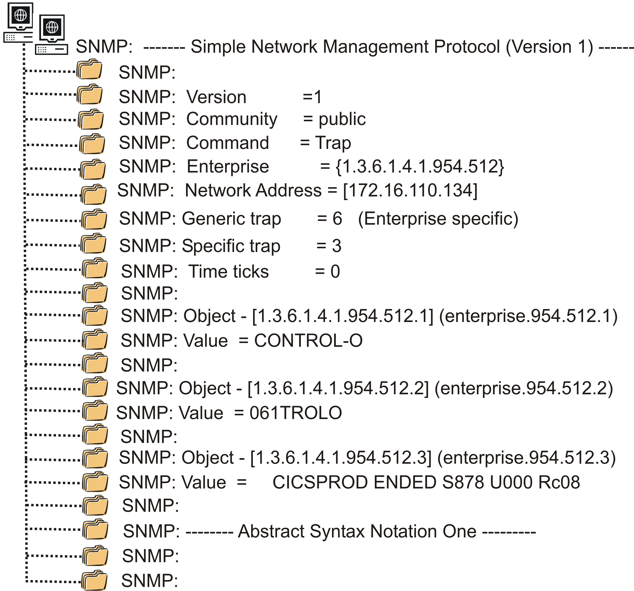
IOA MIB Definitions
Following is a MIB for the SNMP traps sent by the following statements:
-
DO SNMP statement of Control-O
-
DO SHOUT TO U-S:<snmp destination> statement of Control-M.
The MIB is provided in member IOAMIB in the SAMPLE library.
The MIB is used by the software on the trap recipient side to interpret the fields of the trap message.
IOA-MIB DEFINITIONS ::= BEGIN
-- "This file contains the enterprise specific traps (SNMPv1) sent by
--  Control-M and Control-O on the Mainframe."

IMPORTS
        TRAP-TYPE
               FROM RFC-1215
        OBJECT-TYPE
               FROM RFC1155-SMI
        DisplayString
               FROM RFC1213-MIB;

-- The OBJECT ID definitions of the enterprise:

IOA            OBJECT IDENTIFIER ::= { enterprises 954 }
IOAtraps       OBJECT IDENTIFIER ::= { IOA 512 }

-- The three specific traps that can be sent:

veryurgentTrap TRAP-TYPE
       ENTERPRISE IOAtraps
       VARIABLES { product,monitor,text }
       DESCRIPTION "very urgent trap"
       ::= 1

urgentTrap TRAP-TYPE
       ENTERPRISE IOAtraps
       VARIABLES { product,monitor,text }
       DESCRIPTION "urgent trap"
       ::= 2

regularTrap TRAP-TYPE
       ENTERPRISE IOAtraps
       VARIABLES { product,monitor,text }
       DESCRIPTION "regular trap"
       ::= 3
-- The three variables that are included in each trap:

product OBJECT-TYPE
        SYNTAX DisplayString
        ACCESS read-only
        STATUS mandatory
        DESCRIPTION "This is the product name, CONTROL-M or CONTROL-O"
        ::={IOAtraps 1}

monitor OBJECT-TYPE
        SYNTAX DisplayString
        ACCESS read-only
        STATUS mandatory
        DESCRIPTION "This is the job name of the CONTROL-M/O monitor"
        ::={IOAtraps 2}

text   OBJECT-TYPE
        SYNTAX DisplayString
        ACCESS read-only
        STATUS mandatory
        DESCRIPTION "This is the actual text (message) of the trap"
        ::={IOAtraps 3}
 END
Support for SNMPv3 Traps
Control-O and Control-M support SNMPv3 traps by activating the SNMP SUBAGENT feature. When activated, SNMP messages that are generated by DO SNMP statements in Control-O rules or DO SHOUT to U-S statements in Control-M rules, are sent to an SNMP Master Agent.
The SNMP Master Agent is an SNMPD or OSNMPD Server on an OS/390 or z/OS computer, which usually runs on the same mainframe on which Control-O or Control-M resides. Once the messages are received by an SNMP Master Agent, they are forwarded to the SNMP TRAP listeners defined during setup of the SNMP Master Agent.
When the SUBAGENT feature is activated, Control-O and Control-M take on the role of an SNMP sub-agent. Control-O or Control-M send the SNMP traps to the Master Agent, and the Master Agent sends the traps to the SNMP listeners.
The communications between Control-O or Control-M, and the SNMP Master Agent, are carried out by UDP and TCP/IP. The protocol used to communicate with the SNMP Master Agent is the Distributed Protocol Interface (DPI) V1.1.
Activating the SNMPv3 Traps Feature
-
Activate this feature by changing the MODE statement in the IOAPARM member to MODE=SUBAGENT. This can be performed through ICE in the following step:
-
IOA Customization
-
Major step: 1 IOAPARM Post-Installation
-
Minor Step: 3 Specify parameters for "Mail" options
-
-
Additionally, specify valid values for the following SNMP parameters in IOAPARM:
-
host is the hostname or IP address of the host where the Master Agent runs
Default: 127.0.0.1 (the local host) -
port is the SNMP port on which the Master Agent listens for SNMP requests Default: 161
-
community is the community name defined in the Master Agent setup
Default: public
-
When a MODE=SUBAGENT statement is specified in the IOAPARM member then all other NICK and GROUP statements in the SNMPDEST member are ignored.
If MODE is not set to SUBAGENT then it must be set to any other non-blank value, such as MODE=ALONE.
You can switch between activating and deactivating SUBAGENT MODE by changing the MODE parameter and recycling the corresponding monitor(s). If Control-M is used for sending SNMP traps, stop Control-M monitor and then restart it. If Control-O is used for sending SNMP traps, start a new Control-O monitor without stopping the currently running Control-O monitor.
Replacing the Current Destination Tables
When you want to modify or replace either the Dynamic Destination table or the Mail Destination table, you must follow the procedures described in this section.
Replacing the Dynamic Destination Table (IOADEST)
The Dynamic Destination table is loaded when the respective INCONTROL product monitor is started. To replace the current Dynamic Destination table with a new one, use the appropriate operator command for each INCONTROL product installed at your site, as described in the following table:
Table 53 Operator Commands for Replacing the Dynamic Destination member
|
Command Syntax |
Product |
|---|---|
|
F CONTROLM,NEWDEST |
Control‑M |
|
F CONTROLD,NEWDEST |
Control‑D |
|
F CONTROLO,NEWDEST |
Control‑O |
|
F IOAFMON,NEWDEST |
The IOA Functional monitor used by Control‑M/Tape |
The IOADEST table is reloaded and an accompanying message is displayed on the operator console from which the modify command was issued, when the monitor resumes job processing.
Mail Destination Table (MAILDEST)
The Mail Destination table is loaded when the INCONTROL product monitor is started. To replace the current Mail Destination table with a new one, use the appropriate operator command for each INCONTROL product installed at your site.
Table 54 Operator Commands for Loading a New Mail Destination Table
|
Command Syntax |
Product |
|---|---|
|
Copy
|
Control‑M |
|
Copy
|
Control‑O |
|
Copy
|
Control-D |
After a few seconds, a message about the result of the operation is displayed on the operator console from which the modify command was issued.
Message Destination Parameters in IOAPARM
After completing installation, but before sending messages, you must define the appropriate parameters in the IOAPARM member in the IOA PARM library. For email messages, specify the parameters in the MAIL section of IOAPARM describe in the table. For SNMP messages, specify the parameters in the SNMP section of IOAPARM described in the second table. A sample MAIL section of the IOAPARM member is shown below.
Table 55 Parameters in the MAIL section of the IOAPARM member
|
Parameter |
Description |
|---|---|
|
SMTPNAME |
Global parameter. 1 through 8 characters. Has the same value that the ExtWrtName parameter is set to in the CSSMTP configuration. If ExtWrtName is omitted, then by default, SMTPNAME is equal to the local SMTP STC name. Mandatory. |
|
DFLTSFFX |
Global parameter. 1 through 50 characters. The default suffix of the local company e-mail address, in the format mail-id.domain.com. Mandatory. Do not include the @ character. |
|
DFLTRPTO |
This field can hold up to 60 characters. The default full Reply To email address. On replying, this parameter overrides the From address and can be used where a possible reply to an actual address is needed. |
|
DFLTSNDR |
This field can hold up to 25 characters. This parameter enables the site to set a default sender name to be used in the FROM line of all emails sent by the INCONTROL monitors (for example, Control-M monitor) using the DO MAIL function. If this parameter does not appear in the MAILDEST parameter member or if it is left empty, the rule or job owner is used as the sender's name. |
|
OWNRSUFX |
Identifying information that is appended as a suffix to the name of the owner (the owner ID of the Control-M job). The value of this parameter will be appended to the name of the owner of the Control-M job definition. Up to 30 characters. |
|
HOSTNAME |
Global parameter. 1 through 8 characters. Name of the TCP host. Mandatory. |
|
CLASS |
Class of sysout from IOAMAIL to SMTP. 1 character. This must be a JES non-held class. |
|
DEST |
Destination for output of IOAMAIL. 1 through 8 characters. |
|
FORM |
Location of SYSOUT. 1 through 4 characters. The SYSOUT file that is directed to the SMTP will include the value of the FORM parameter. |
|
ENVELOPE |
Determines how IOAMAIL envelopes the mail message and which skeleton members are used. Valid values are:
In both cases, the skeleton member IOASMTPA is used for attachment data. For more information about the Skeleton members, see SMTP Skeleton Member. |
|
TIMEZONE |
Time zone used to set message transmission time. 5 characters can be used to identify a recognizable time zone. Default: LCL (local time zone) |
|
ATSIGN |
The AT SIGN (@) value that will be used as separator between the name and its address. It is useful when a site uses a pagecode in which the @ character is not X'7C'. |
|
ATCHSET |
Character set For example, ISO-8859-1. |
|
ATCHENC |
Character encoding. For example, 8. |
|
CTMLMAIL |
Specifies whether Control-M will write a message to the IOA Log whenever it sends a mail message. Email can be sent via the DO EMAIL, DO SHOUT, or SHOUT WHEN statements. Values:
|
Table 56 Parameters in the SNMP section of the IOAPARM member
|
Parameter |
Description |
|---|---|
|
MODE |
Global parameter. 1 through 8 characters. Mode of SNMP. Mandatory. For example, SUBAGENT. |
|
HOST |
Global parameter. IP address or the host name. Mandatory. Host name (1 through 64 characters) or IP address (standard dotted-decimal notation) of an SNMP destination. |
|
PORT |
SNMP port number (1 through 65535). If not specified, SNMP port number defaults to 162. |
|
COMMUNTY |
This field can hold up to 32 characters. Community in Master Agent setup. If this parameter does not appear in the MAILDEST parameter member or if it is left empty, the rule or job owner is used as the sender's name. |
Figure 5 Sample MAIL section in IOAPARM
 *-------------------------------------
 *        MAIL parameters
 *-------------------------------------
 MAIL     SMTPNAME=SMTP,           Name of SMTP STC
 * The suffix of company's mail address:
           DFLTSFFX=BMC.COM,
 * Reply-To Email Address:
          [email protected],
          DFLTSNDR=bmc_sender,     The default 'From' name
          OWNRSUFX=,               To be appended to DFLTSNDR
          HOSTNAME=MVS3,           Host Name
          CLASS=A,                 Class of SMTP sysout
          DEST=LOCAL,              Destination for mail
          FORM=,                   FORM name for sysout
          ENVELOPE=IBM,            EMAIL format: IBM or CA
          TIMEZONE=,               Indicates the time zone
          ATSIGN=@,                Separator the owner from domain
          ATCHSET=ISO-8859-1,      Character set
          ATCHENC=8                Character encoding
 *-------------------------------------
SMTP Skeleton Member
This member is used for skeletons on the SMTP protocol.
Main skeleton members:
-
IOASMTPI is used if the system is set up to use the IBM format for SMTP.
-
IOASMTPC is used if the system is set up to use the CA format for SMTP.
Attachment skeleton member:
-
IOASMTPA is used in both cases (IBM format and CA format) only if attachment of the SYSOUT is required.
-
A single "*" at the start of a line in the skeleton members, not followed by "#", signifies a comment, and such a line is ignored by the program.
-
Lines that begin with "*#" in IOASMTPI or IOASMTPC are replaced by the corresponding lines from IOASMTPA if an attachment of the SYSOUT is required.
General IP parameters
The IP section in IOAPARM affects the following components:
-
SNMP
-
Immediate PC file transfers from online (Option U).
-
Delayed PC file transfers by Control-D File Transfer Monitor.
Table 56a Parameters in the IP section of the IOAPARM member
|
Parameter |
Description |
|---|---|
|
ISOCKAPI |
TCP/IP socket API type. Valid values:
When SAS is specified, SAS/C-written modules are used and TCP/IP support will be at the same level as in INCONTROL Version 8.0.00 (IPv6 not supported). When IBM is specified or implied, SNMP and Control-D use IBM C-written modules and support IPv6 and dual TCP/IP stacks. |
|
ISTACK |
TCP/IP stack name. This is the started task name of a TCP/IP stack that is active on the z/OS system. If specified, stack affinity is established. Default: The z/OS system's default TCP/IP stack is used. If the z/OS system is not configured for dual stack mode, then the parameter is ignored. But if it is and the stack is not running, then the file or SNMP transmission will not be processed. Warning: Specifying a stack might affect connectivity and hostname resolution. Consult your network administrator. |
|
IPVMODE |
TCP/IP protocol implementation level. Valid values:
When IPV4 is specified, IPv6 is not supported. |
IOAMAIL
IOAMAIL can be called by Control‑M and Control‑M/Analyzer, using appropriate subparameters under the DO MAIL or DO SHOUT parameters in a job scheduling definition.
IOAAPI can also be used as an entry point to the IOAMAIL facility. For more information on IOAAPI, see IOAAPI.
Specifying a MAIL Destination
The destinations for e-mail messages sent by IOAMAIL can be specified using several methods, enabling you to send a single e-mail message to several destinations. Different methods can be used for the destinations.
IOAMAIL e-mail destinations can be specified using:
-
a fully specified destination name
-
Example: [email protected]
-
-
a user name, without specifying any more information
-
IOAMAIL uses the DFLTSFFX parameter in the IOAPARM member as the default suffix for the user name. The result is a fully specified destination name.
-
Example
-
If you specify joe_smith, and the default suffix in the DFLTSFFX parameter is acme.com, IOAMAIL completes the resulting e-mail address as [email protected]. (Note that the @ character is taken from the ATSIGN parameter in the IOAPARM member.)
-
-
a nickname, without specifying any more information
-
IOAMAIL searches for the nickname in the set of predefined nicknames in the MAILDEST member. Each nickname and full e-mail address are specified in separate lines in that member.
-
For example, if Joe Smith has the e-mail address [email protected], and is to be given the nickname JOE, the definition will appear in the MAILDEST member as
-
NICK=JOE
[email protected] -
If the destination of an IOAMAIL e-mail is then specified as joe, the e-mail address results in [email protected].
-
-
a GROUP name, without specifying any more information
-
Each IOAMAIL GROUP consists of a group of e-mail recipients. Such a group can comprise any number of e-mail destinations. Each such destination can be defined by reference to
-
-
a full e-mail address
-
a user name, where the DFLTSFFX parameter in the IOAPARM member is used as the suffix
-
an IOAMAIL nickname specified as described above
Each destination must be prefixed with the notation TO or CC. When prefixed TO, the e-mail is sent to that destination as an addressee. When prefixed CC, the e-mail is sent to that destination as a copy.
For more information on the MAILDEST member, see The Mail Destination Table
IOA support for DO REMEDY
The DO REMEDY option in Control-M for z/OS enables creation of a problem ticket in the Remedy Help Desk system by sending a formatted e-mail to a special mailbox that is defined for this purpose. For more information about the DO REMEDY option, see the Control-M for z/OS User Guide.
The Remedy Email Engine reads the incoming message sent to this mailbox and creates problem tickets in the Remedy system, according to the details in each message.
To set up IOA support for DO REMEDY
-
Create an account on a POP3 mail server (for example, Microsoft Exchange Server) and record the following details:
-
Server name or IP address of the POP3 server (for incoming mail)
-
Server name or IP address of the SMTP server (for outgoing mail)
-
Server port number used for connecting to the POP3 server (for incoming mail)
-
Server port number used for connecting to the SMTP server (for outgoing mail)
-
Mailbox name and password
-
E-mail address of this new account
BMC recommends that you ensure that the new mail account has been set up correctly by trying to access the account from Microsoft Outlook. In Outlook, select Tools=> E-mail Accounts=> Add a new E-mail account=> POP3. After you have filled in the details, press Test Account Settings.
-
-
Install and configure the Remedy Email Engine.
-
Ensure that the Java SDK is already installed on the computer where the Remedy Email Engine will be installed.
For detailed instructions about installing the Remedy Email Engine, see the Action Request System 6.3 Remedy Email Engine Guide.
Remedy Email Engine configuration guidelines
-
Do not specify an RPC port during the first part of the Remedy Email Engine installation.
-
Define the same name for the incoming and outgoing mailboxes during the mailbox configuration part of the Remedy Email Engine installation.
-
When you configure the Remedy Email Engine, specify only the host name (without the domain name) as the SMTP server.
-
BMC recommends that until DO REMEDY has been tested to work successfully, instead of starting the Remedy Email Engine as a service, start it by running the following batch file. Set the debug flag so that debugging messages will go to the command window.
Edit the emailstart.bat file and add the -Dmail.debug=true option after "%JavaPath%\java":
Copy"%JavaPath%\java" -Dmail.debug=true -cp
emaildaemon.jar;arapi63.jar;arutil63.jar;activation.jar;mail.jar;imap
.jar;smtp.jar;pop3.jar;armapi63.jar
com.remedy.arsys.emaildaemon.EmailDaemonThe default location of the emailstart.bat file is C:\Program Files\AR System\AREmail.
-
There are additional parameters in the Remedy Email Engine mailbox configuration that cannot be set up in the initial prompt windows. You can access the setup values later by selecting Start=> Programs=> Action Request System=> ARSystem User. After logging on, perform the following steps:
-
Select Open=> Find and specify AR System Email Mailbox Configuration.
-
Select the entry that has type Form and click the Search icon. This process should find two mailboxes: Incoming and Outgoing.
-
Select the Incoming mailbox and change Polling Interval (Minutes) to 1.
-
Press Advanced Configuration.
-
Change Reply With Result to No and save your changes.
-
Restart the Remedy Email Engine.
-
-
-
Copy members REMCONFD and REMTMPL from the IOA.BASE.GENERAL library to the IOA.PARM library.
-
Create a copy of REMCONFD in the IOA.PARM library, and name it REMCONF.
-
Configure the parameters in member REMCONF, as described in REMCONF member.
-
Create a copy of REMTMPL in the IOA.PARM library, and name it REMTMPLx, where x is the suffix specified in the REMTPLS parameter of the REMCONF member.
-
Configure the email template in the REMTMPLx member, as described in REMTMPLx member.
-
Define the nickname and email address defined in REMMAIL parameter of REMCONF member in the MAILDEST member (see note below).
-
Recycle the Control-M Monitor.
The following MAILDEST parameters, which are related to the Remedy interface in version 6.3.01 and earlier, are no longer supported: RMxSRV, RMxUSR, RMxPSW, RMxSCM, RMxSRC, RMxSTS, RMxTYP. In this list, the value of x may be M, D, or O. If these parameters are set in the MAILDEST member, they will be ignored.
Understanding the DO REMEDY configuration members
The Remedy interface contains the following configuration members:
-
REMCONF member contains general customization parameters for Remedy. For details, see REMCONF member.
-
REMTMPLx member or members contain formatted email templates. For details, see REMTMPLx member.
REMCONF member
The REMCONF member contains general customization parameters for Remedy.
The REMCONF member contains separate sections for the different IOA products. Each section begins with the COMPID field, and all parameters that follow that field relate to the product specified in it.
A sample member named REMCONFD is provided in IOA.BASE.GENERAL library, which must be manually copied as REMCONF in order to use it. A default REMCONF member is not provided, to avoid overwriting. An asterisk in column 1 indicates a comment.
Table 57 REMCONF parameters
|
Name |
Description |
|---|---|
|
COMPID |
Begins a component section for an IOA product. Mandatory. The only valid value is M (Control-M). |
|
REMMAIL |
Nickname of the Remedy email address. Mandatory. Must be defined as a regular email address in the MAILDEST member in the IOA.PARM library. |
|
REMMSUB |
Email subject, composed of free text. Default: null. Limited to 60 characters. |
|
REMTMPLS |
A single character used as a suffix for pointing to the email template to be used when tickets are opened in Remedy. Mandatory. The email template member that will be used is REMTMPLx, where x is the specified suffix. The member will be used from the IOA.PARM library. |
|
REMTRNL |
Translate value for URGENCY=L (low). Mandatory. Limited to 60 characters. Composed of free text (not null). Text must be surrounded by single quotes. |
|
REMTRNM |
Translate value for URGENCY=M (medium). Mandatory. Limited to 60 characters. Composed of free text (not null). Text must be surrounded by single quotes. |
|
REMTRNH |
Translate value for URGENCY=H (high). Mandatory. Limited to 60 characters. Composed of free text (not null). Text must be surrounded by single quotes. |
|
REMTRNU |
Translate value for URGENCY=U (urgent). Mandatory. Limited to 60 characters. Composed of free text (not null). Text must be surrounded by single quotes. |
|
REMTRNB |
Translate value for URGENCY= (blank). Mandatory. Limited to 60 characters. Composed of free text (not null). Text must be surrounded by single quotes. |
Sample REMCONF member
The values specified in the REMTRNx parameter are used to replace the URGENCY value specified in the rule Control-M rule with the value that should be used in the Remedy ticket. Refer to "%%URGENCY%%" in REMTMPLx member.
***************************************************************
** REMCONF - Remedy Interface Configuration                  **
**                                                           **
** The member should be copied as REMCONF and to reside in   **
** the IOA.PARM library.                                     **
**                                                           **
** Please refer to the INCONTROL for z/OS Administrator      **
** Guide for more information.                               **
**                                                           **
** Notes:                                                    **
** ------                                                    **
**                                                           **
** (1) A sample of the a Remedy Email template (pointed by   **
**     the REMTMPLS= parameter) can be found in member       **
**     REMTMPL.                                              **
**                                                           **
** (2) Use the following REMTRNx settings for                **
**     Remedy release 6:                                     **
**                                                           **
**       REMTRNL='Low'                                       **
**       REMTRNM='Medium'                                    **
**       REMTRNH='High'                                      **
**       REMTRNU='Urgent'                                    **
**       REMTRNB='Medium'                                    **
**                                                           **
**     Use the following REMTRNx settings for                **
**     Remedy release 7:                                     **
**                                                           **
**       REMTRNL='4-Low'                                     **
**       REMTRNM='3-Medium'                                  **
**       REMTRNH='2-High'                                    **
**       REMTRNU='1-Urgent'                                  **
**       REMTRNB='3-Medium'                                  **
**                                                           **
** (3) Email nick name defined by parameter REMMAIL= should  **
**     be defined in member MAILDEST.                        **
**                                                           **
***************************************************************
**
** Control-M Section
**
  COMPID=M
    REMMAIL=CTMRMDY
    REMMSUB=
    REMTMPLS=M
    REMTRNL='Low'
    REMTRNM='Medium'
    REMTRNH='High'
    REMTRNU='Urgent'
    REMTRNB='Medium'
The sample REMCONFD member is similar.
REMTMPLx member
The REMTMPLx member holds the email template to be used for opening a ticket in Remedy. The REMTMPLS parameter in the REMCONF member points to the REMTMPLx email template member, where x is a free suffix pointing to the required member.
Basic configuration information (such as Remedy server name, schema name, user name, and password) is an integral part of the template.
The member supports mixed case characters (CAPS OFF).
Each line is limited to 70 alphanumeric characters.
A sample template named REMTMPL is provided, and includes separate samples to be used with Remedy 6 and Remedy 7. Instructions on how to configure the member, including the configuration parameters, are included as comments. The sample must be manually copied as REMTMPLx, where x is the suffix specified in the REMTPLS parameter.
The email will be sent to the address pointed by the nickname specified in the REMMAIL parameter, and the email subject is set as specified in the REMMSUB parameter (both of which are located in the REMCONF member).
When the email is built, the template strings are replaced with the values as described in the table.
Table 58 REMTMPL template variables
|
String in template |
Replace by Value |
Comments |
|---|---|---|
|
%%SUMM%% |
The SUMM field as specified in the Control-M rule. |
Mandatory. No default. |
|
%%DESC%% |
The DESC field as specified in the Control-M rule. |
Mandatory. No default. |
|
%%URGENCY%% |
The URGENCY field as specified in the Control-M rule. This takes place after the appropriate translation using the REMTRNx parameters in the REMCONF member. |
Default: the value specified in the REMTRNB parameter in the REMCONF member. |
|
%%USER%% |
The user ID that created the Control-M rule that issued the Remedy ticket opening request. |
Mandatory. No default. |
Sample template
********************************************************************
** REMTMPLx - Remedy Email Template                               **
**                                                                **
** This is a sample of a Remedy Email template to be used in      **
** order to open a ticket in Remedy.                              **
**                                                                **
** The email template should reside in IOA.PARM library and to    **
** be named as REMTMPLx where x is the charater specified in      **
** parameter REMTMPLS= in member IOA.PARM(REMCONF).               **
**                                                                **
** This sample includes 2 separate sections:                      **
**  - The first section should be used with Remedy release 6.     **
**  - The second section should be used with Remedy release 7.    **
**                                                                **
**----------------------------------------------------------------**
** Steps needed to be done to customize the template:             **
**                                                                **
** a.  Select the sample appropriate to your Remedy               **
**     level (6 or 7).                                            **
**                                                                **
** b.  Remove (or comment using an asterisk in column 1)          **
**     the sample related to the Remedy level not used on         **
**     your site.                                                 **
**                                                                **
** c.  Fill in the customization parameters as defined in         **
**     your site:                                                 **
**                                                                **
**      - The Remedy schema name used for opening the ticket      **
**      - The Remedy server name                                  **
**      - The Remedy user name                                    **
**      - The Remedy User password                                **
**                                                                **
** d. Add additional Remedy fields that are required on           **
**    on your site as additional lines at the bottom of           **
**    the template.                                               **
**                                                                **
** e. The member should be placed in the IOA.PARM library         **
**    and to be named REMTMPLx where X is the suffix              **
**    specified in parameter REMTMPLS in member REMCONF           **
**    which resides in the same library.                          **
**                                                                **
** Please refer to the INCONTROL for z/OS Administrator           **
** Guide for more information.                                    **
**                                                                **
********************************************************************
** Remedy 6 sample                                                **
** ---------------                                                **
** Use the following section for Remedy release 6.                **
** Don't forget to remove the section for Remedy release 7 below. **
********************************************************************
Schema: HPD:HelpDesk
Server: remsrvr
Login: Demo
Password:
Action: Submit
Format: Short
Summary* !        8!: %%SUMM%%
Description* !240000007!: %%DESC%%
Category* !200000003!: Software
Type* !200000004!: Other
Item* !200000005!: Other
Login*+ !240000005!: %%USER%%
Name*+ !240000001!: %%USER%%
Source* !260000128!: Email
Solution Details !260000503!:
Status* !        7!: New
Case Type* !260000130!: Incident
Urgency !240000009!: %%URGENCY%%
**
********************************************************************
** Remedy 7 sample                                                **
** ---------------                                                **
** Use the following section for Remedy release 7.                **
** Don't forget to remove the section for Remedy release 6 above. **
********************************************************************
char-set: windows-1252
Schema: HPD:IncidentInterface_Create
Server: remsrvr
Login: Demo
Password:
Action: Submit
Description !1000000000!: %%SUMM%%
Service Type !1000000099!: User Service Request
Status !         7!: New
Details !1000000151!: %%DESC%%
First Name* !1000000019!: App
Last Name* !1000000018!: Admin
First Name+ !1000005783!: %%USER%%
Last Name+ !1000005782!: %%USER%%
Impact* !1000000163!: 3-Moderate/Limited
Urgency* !1000000162!: %%URGENCY%%
!1000000076!: CREATE
**
********************************************************************
** Version 7.6.04                                                 **
** If you want to specify values for the First Name+ and          **
** Last Name+ parameters in the REMTMPLx member, you must define  **
** these values as user with valid First and Last names in Remedy,**
** then remove the asterisks from the First Name+ and Last Name+  **
** fields, and then specify values of the defined First and Last  **
** names.                                                         **
********************************************************************
char-set: windows-1252
Schema: HPD:IncidentInterface_Create
Server: remsrvr
Login: Demo
Password:
Action: Submit
Description !1000000000!: %%SUMM%%
Status !         7!: New
Details !1000000151!: %%DESC%%
First Name* !1000000019!: App
Last Name* !1000000018!: Admin
*Uncomment the  First Name+ and Last Name+ if defined in Remedy
*First Name+ !1000005783!: %%USER%%
*Last Name+ !1000005782!: %%USER%%
Service Type !1000000099!:1
Impact* !1000000163!: %%URGENCY%%
Urgency* !1000000162!: %%URGENCY%%
!1000000076!: CREATE
RepSource !1000000215!:email
The sample REMTMPL member is similar.
In the sample provided for Remedy version 7.6.04, the lines for the First Name+ and Last Name+ parameters are commented out with asterisks (*) so that by default a Remedy ticket is produced.
If you want to specify values for the First Name+ and Last Name+ parameters in the REMTMPLx member, you must define these values as a user with valid first and last names in Remedy, then remove the asterisks from the First Name+ and Last Name+ fields, and specify the values of the defined First and Last names.
IOAAPI
IOAAPI, the IOA Application Program Interface, provides an interface to some IOA services.
Supported Services
IOAAPI currently supports the services described in the following table:
Table 59 Services Supported by IOAAPI
|
Service |
Description |
|---|---|
|
COND |
Processes a condition file |
|
|
Sends messages by e-mail |
|
LOG |
Selects records from the log |
Access to IOAAPI
IOAAPI can be accessed by the following means:
-
a batch program
-
a batch statement
-
use of the TSO command processor
-
a user application program
Service Types Syntax
A service call is made using the following syntax:
service_type service_parmswhere
-
service_type is one of the supported services
-
service_parms are parameters sent along with the service_type
To write a comment in a call string, place an * (asterisk) before the first character. Use this technique if, for example, you want a call string to be omitted from one run of a job.
COND Service
The following is the syntax of a request for the COND service:
COND request_type condition_name date
where:
-
request_type is one of the following types of request:
-
ADD
-
DELETE
-
CHECK
-
condition_name is the name of the condition, from 1 through 40 characters
-
date is the date in mmdd format
-
-
Return Codes
The ADD request returns condition code 0 when successfully executed and the condition code does not exist. If the condition_name already exists, the condition code is 8.
The DELETE request returns condition code 0 when successfully executed and the condition name exists, unless there was no condition_name, in which case the condition code is 8.
Details of all the COND return codes appear in the following table:
Table 60 IOAAPI COND Return Codes
|
Return Code |
Explanation |
|---|---|
|
0 |
OK |
|
4 through 56 |
CTMURS error code |
|
The CHECK request returns condition code 8 when the condition_name does not exist. If it does exist, the code returned is 0. |
|
|
100 |
PARM string parsing error |
|
104 |
Unable to get storage |
|
108 |
Unable to load module |
|
112 |
Unable to build MCT |
|
116 |
Failed to open a file |
|
120 |
Error in calling sequence for command processor |
|
124 |
Unrecognized service type |
|
128 |
IEANTXX error |
|
132 |
Error in IF statement |
Examples
COND ADD A_LONG_CONDITION_NAME 0822
COND DELETE CONDITION_ALPHA 1231
COND CHECK ANY-CONDITION 0407
MAIL Service
Before using this service, ensure that you are familiar with IOAMAIL.
The MAIL service can only be used in batch and API runs.
The following is the syntax of a request for the MAIL service:
MAIL request_type(content)where
-
request_type is one of the types of request shown in the following table
-
content of the request type, as explained under "Description" in the following table
Table 61 MAIL Request Types
|
Request Type |
Description |
|---|---|
|
TO |
Mandatory. Address of recipient of the e-mail, specified in one of the ways described in IOAMAIL. Many TO requests can be specified in successive lines in one MAIL request. |
|
CC |
Optional. Address of recipient of a copy of the e-mail, specified in one of IOAMAIL ways described in IOAMAIL. Many CC requests can be specified in successive lines in one MAIL request. |
|
SUBJ |
Optional. Text for the subject field of the e-mail. If more than one SUBJ is specified, the last specified is used. |
|
TEXT |
Mandatory. Text for the body of the e-mail message. Up to 10 TEXT lines can be specified. |
|
SEND |
Mandatory. This Request Type has no text field. It sends the prepared e-mail. The message subject and text lines of the e-mail are cleared after sending is complete. |
|
NEWL |
This Request Type has no text field. It clears the recipient lists, both TO and CC. |
Return Codes
Details of all the MAIL return codes appear in the table.
Table 62 IOAAPI MAIL Return Codes
|
Return Code |
Explanation |
|---|---|
|
0 |
OK |
|
4 |
From IOAMAIL |
|
8 |
From IOASMTP |
|
100 |
PARM string parsing error |
|
104 |
Unable to get storage |
|
108 |
Unable to load module |
|
140 |
Attempting to request MAIL by means of a PARM or from TSO command processor |
|
144 |
Too many text lines |
|
148 |
Unrecognized MAIL parameter |
The following is an example of a MAIL request:
MAIL TO [email protected] TO GEORGE
MAIL CC CLARA
MAIL SUBJ subject-header-text
MAIL TEXT text-line1
MAIL TEXT text-line2
MAIL TEXT text-line3
MAIL SEND
LOG Service
The LOG service can only be used in batch and API runs. The syntax of a request for the LOG service is
LOG request_type [parm1] [parm2]where
-
request_type is one of the types of request shown in the tablebelow
-
parm1 and parm2 depend on the type of request specified as request_type
Table 63 LOG Service Request Types
|
Request Type |
Description |
|---|---|
|
DATE |
Only records between the two dates specified are to be selected. If DATE is not specified, records of any date can be selected. The syntax of the request is Copy
|
|
TIME |
Only records between the two times specified are to be selected. If DATE is not specified, the TIME parameter is ignored. If DATE is specified but TIME is not specified, all times can be selected. The syntax of the request is Copy
where hh follows the 24-hour clock format. |
|
CODE |
Provides a list of message codes. Depending on the syntax of the request, this request code may (using CODE IN) specify the message codes to be included in the list, or (using CODE NOT IN) those to be excluded from the list. The syntax of the request is Copy
or Copy
When many CODE requests are specified, the program joins them into one list containing a maximum of 100 codes. However, all CODE requests must be of the same type, that is, they must all be either IN or NOT IN. If CODE is not specified, all codes can be selected. |
|
FILE |
All selected log records are written to a file. The user must supply a JCL DD statement specifying the file. The syntax of the request is Copy
The default value of ddname is DAAPIOUT. The DAAPIOUT default should not be used when the selected log records have to be written to a file. The file should be allocated with LRECL=200 and RECFM=FB. |
|
RECORD |
The records selected are passed to the calling API. This request type is ignored where there is no API. FILE and RECORD are mutually exclusive. If neither is specified in an API environment, the default is RECORD. |
|
FIND |
Perform the selection of log records as specified by the other parameters (that is, DATE, TIME, CODE, FILE, and RECORD). If FILE was specified, all records are written to file. If RECORD was specified, the first record is pointed by the register R1. The following records are passed by the NEXT request. |
|
NEXT |
Passes one log record to the calling program. This request type is valid only in an API environment. On return to the API, if the record was passed OK, the value in register R15 is zero, and R1 points to the next record. When the end of the LOG is reached, the value in register R15 is 4. |
Return Codes
Details of all the LOG return codes appear in the table.
Table 64 IOAAPI LOG Return Codes
|
Return Code |
Explanation |
|---|---|
|
0 |
OK. |
|
4 |
In RECORD mode, end of log reached. |
|
8 |
Error. This return code is accompanied by an explanatory message. |
|
100 |
Parameter string error. |
|
104 |
Unable to get storage. |
|
116 |
Failed to open a file. |
|
140 |
Calling sequence for a CP IN error |
|
148 |
Request type unknown. |
|
152 |
Too many codes in list. |
|
156 |
The request includes both CODE IN and CODE NOT IN request types. |
|
160 |
Error in the DATE or TIME request. |
|
164 |
Either both FILE and RECORD request types requested, or neither was requested. |
|
168 |
The request included a NEXT without a preceding FIND. |
|
172 |
FIND was called twice. |
The following is an example of a LOG request:
LOG DATE BETWEEN 010815 AND 010831
LOG TIME BETWEEN 0800 AND 1800
LOG CODE IN SEL154L SQR606I
LOG CODE IN YQR312I
LOG FILE MYFILE
LOG FIND
Using a Batch Program
Within a batch program, a service request is submitted as the PARM field specification in an EXEC statement.
//EXAM1      EXEC PGM=IOAAPI
//     PARM=’COND ADD COND1 0401’
//STEPLIB DD DISP=SHR,DSN=dataset1
//     DD DISP=SHR,DSN=dataset2
//DAAPIOUT DD SYSOUT=*
//DAPARM DD DISP=SHR,DSN=dataset3
//DACNDF DD DISP=SHR,DSN=dataset4
//DALOG DD DISP=SHR,DSN=dataset5
where
-
dataset1 and dataset2 are STEPLIB libraries, set on installation
-
dataset3 is the Parameters Dataset file, and is mandatory
-
dataset4 is the Conditions file used for COND requests
-
dataset5 is the Log file used for LOG requests
Only one request can be made in a batch program.
Using Batch Statements
Requests are passed as an input file. Each record is 80 bytes in length, but only the first 71 bytes are used.
The following example illustrates the use of a batch statement to issue a series of requests:
//EXAM2     EXEC PGM=IOAAPI
//STEPLIB DD DISP=SHR,DSN=dataset1
//     DD DISP=SHR,DSN=dataset2
//DAAPIOUT DD SYSOUT=*
//DAPARM DD DISP=SHR,DSN=dataset3
//DACNDF DD DISP=SHR,DSN=dataset4
//DALOG DD DISP=SHR,DSN=dataset5
//DAAPIPRM DD *
     COND DELETE COND2 0115
     COND ADD COND3 0701
     COND CHECK COND4 1231
     MAIL TO USER2
     MAIL CC [email protected]
     MAIL SUBJ RUN ENDED
     MAIL TEXT RUN OF TODAY FINISHED OK
     MAIL SEND
     LOG DATE BETWEEN 010401 AND 010415
     LOG CODE IN MTO356I MTO357I
     LOG FILE PRINT
     LOG FIND
//
where
-
dataset1 and dataset2 are STEPLIB libraries, set on installation
-
dataset3 is the Parameters dataset file; this must be present
-
dataset4 is the Conditions file used for COND requests
-
dataset5 is the Log file used for LOG requests
Conditional Input
Requests passed from a batch statement can be conditional, using the following syntax:
IF LASTCC condition number THEN
      statement_1
      statement_2
      statement_3
      .....
ELSE
      statement_4
      statement_5
      statement_6
      .....
ENDIF
where
-
LASTCC is the condition code returned by the last executed request
-
condition is either EQ (Equal) or NE (Not Equal)
-
number is a numeric value from 1 through 3 digits, for example 4, 04, or 004
Tokens in the IF statement must be separated by blanks. Nested IF statements are not supported. The whole IF statement must reside in the same input record.
ELSE and its group of statements are optional. If used, it must be the only token in a record.
ENDIF must be the only token in a record.
COND CHECK CONDITION_A 0104
IF LASTCC EQ 8 THEN
     COND ADD CONDITION_A 0104
ELSE
     COND ADD CONDITION_B 0104
     MAIL TO USER1
     MAIL TEXT CONDITION_B ADDED
     MAIL SEND
ENDIF
Using the TSO Command Processor
A request can be made using the TSO command processor. The command is passed as a PARM to the command processor.
The format of the command is
IOAAPI COND condition_request condition_name dateUsing a User Application Program
Any number of requests can be made using a user application program.
In this guide, CLnn means a character field nn characters in length, padded with blanks to the right.
When the request is made, the following array of addresses is passed:
-
A(string1), where string1 is CL8'IOAAPI'
-
A(MCTADDR)
-
A(string2), where string2 is one of the following, as appropriate:
-
CL8'COND'
-
CL8'MAIL'
-
CL8'LOG'
-
In the case of each of the services to which these strings refer, that is, COND, MAIL, and LOG, additional addresses are passed. These additional addresses vary according to the service requested, as explained in the following sections.
COND Service Additional Addresses
For more information on the COND service, see COND Service.
The additional addresses that are passed when the COND service is requested are:
-
A(string3C), where string3C is CL8'request_type'
-
A(string4C), where string4C is CL39'condition_name'
A(string5C), where string5C is CL4'date'
The request_type, condition_name, and date strings have the meanings explained in COND Service.
MAIL Service Additional Addresses
For more information on the MAIL service, see MAIL Service.
Additional addresses that are passed when the MAIL service is requested are:
-
A(string3M) where string3M is CL8'request_type'
-
A(string4M) where string4M is CL70' content'
The request_type and content strings have the meanings explained in MAIL Service.
LOG Service Additional Addresses
For more information on the LOG service, see LOG Service.
The additional addresses that are passed when the LOG service is requested depend on the request type, as follows:
-
A(string3L) where string3L is CL8'request_type'
-
A(string4L) and A(string5L)
where
-
request_type is one of the LOG request types described in LOG Service.
-
the contents of string4L and string5L depend on the type of request specified in string3L as the request_type, as explained in LOG Service.
DATE Request Type Additional Addresses
In the case of the DATE request type, the additional addresses are as follows:
-
A(string3LD), where string3LD is CL8'DATE'
-
A(string4LD), where string4LD is the DATE BETWEEN ("from") date in the format CL8'yymmdd'
-
A(string5LD), where string5LD is the DATE AND ("until") date in the format CL8'yymmdd'
For more information on DATE, DATE BETWEEN, and DATE AND, see LOG Service.
TIME Request Type Additional Addresses
In the case of request type TIME, the additional addresses are as follows:
-
A(string3LT), where string3LT is CL8'TIME'
-
A(string4LT), where string4LT is the TIME BETWEEN ("from") time in the format CL8'hhmm'
-
A(string5LT), where string5LT is the TIME AND ("until") time in the format CL8'hhmm'
For more information on TIME, TIME BETWEEN, and TIME AND, see LOG Service
CODE Request Type Additional Addresses
In the case of request type CODE, the additional addresses are as follows:
-
A(string3LC), where string3LC is CL8'CODE'
-
A(string4LC), where string4LC is either CL8'IN' or CL8'NOT IN'
-
A(string5LC), where string5LC is CL70'code1 code2 code3 ...'
For more information on CODE, IN, and NOT IN, see LOG Service.
FILE Request Type Additional Addresses
In the case of request type FILE, the additional addresses are as follows:
-
A(string3LFL), where string3LFL is CL8'FILE'
-
A(string4LFL), where string4LFL is CL8'ddname'
The string ddname is a DDname of up to 8 characters, and is fully explained, together with its default value of PRINT, in LOG Service.
RECORD Request Type Additional Addresses
In the case of request type RECORD, there is a single additional address, namely, A(string3LR), where string3LR is CL8'RECORD'.
For more information, see LOG Service.
FIND Request Type Additional Addresses
In the case of request type FIND, there is a single additional address, namely, A(string3LFN), where string3LFN is CL8'FIND'.
For more information, see LOG Service.
NEXT Request Type Additional Addresses
In the case of request type NEXT, there is a single additional address, namely, A(string3LN), where string3LN is CL8'NEXT'.
For more information, see LOG Service
IOA Variable Database Facility
The IOA Variable Database facility is comprised of a series of screens and a set of files that enable you to view, create and modify AutoEdit variables that are made available globally to INCONTROL products.
The IOA Variable Database facility is available to Control‑M only with the CMEM monitor active, or when the Control‑O monitor is active.
IOA variable databases are stored in a common storage area on a computer, and are organized into databases. Changes to the value of an AutoEdit variable in an IOA variable database can be accessed by all Control‑M jobs or Control‑O rules on that computer, or, if desired, in the Sysplex if that computer is part of a Sysplex.
When an INCONTROL product starts, the product reads the databases defined in the IOA Variable Database facility and loads the databases’ AutoEdit variables into memory.
Control‑O users can create and access an unlimited number of AutoEdit databases. Other INCONTROL products, such as Control‑M, can only access one AutoEdit database, named IOAVAR.
IOA Variable Database facility databases are specified in the global member list, which is the list of members referenced by DD statement DAGLBLST of the INCONTROL product monitor procedure (currently, either CONTROLO or CTMCMEM). For more information about the global member list, see Defining a New Database.
The IOA Variable Database facility consists of the following files, which are allocated during IOA installation. These files are used to copy information into memory on each computer in which an INCONTROL product is working.
Table 65 IOA Variable Database Facility Files
|
File |
Description |
|---|---|
|
Database file (DBS) |
Contains information about each AutoEdit database, listed in the Definition file. This information is displayed in the List of Databases screen. |
|
Column file (COL) |
Contains information about columns in all databases listed in the Columns file. Columns represent the attributes (fields) stored in each database. The columns for a specific database are displayed in the List of Columns screen for that database. The IOAVAR database file, which is the only database Control‑M (and other INCONTROL products) can access, has two fixed columns: VARNAME and VALUE. The columns of other databases, accessible by Control‑O only, can be defined as you need. |
|
Variables file (VAR) |
This file stores the actual values for each AutoEdit variable in the database. This information is displayed in the Display screen. |
The IOA Variable Database facility files are IOA Access Method files. Each file consists of two operating system files: a data component and an index component. For more information about the IOA Access Method, see IOA Concepts and Components.
Updates and additions made to the AutoEdit variables directly in memory (such as by rules or KOA scripts) are kept in memory by the INCONTROL product and are available to all other jobs, rules, and so on. While the INCONTROL product is active, a specific database (or all databases) can be reloaded from or written to the IOA Variable Database facility files using operator commands LOADGLOBAL and WRITEGLOBAL. When the INCONTROL product is stopped, command WRITEGLOBAL is automatically performed to update all databases with the latest information.
If Control‑O is installed, the CMEM facility is executed by the Control‑O monitor instead of the CMEM monitor. In this case, references in this section to the CMEM monitor apply to the Control‑O monitor, and operator commands contain the string CONTROLO instead of CTMCMEM.
Also, AutoEdit databases are not stored as partitioned datasets. Therefore, the AutoEdit variables stored in these databases cannot be accessed by Control‑M %%LIBSYM and %%MEMSYM control statements. For Control‑M to access these variables, you must explicitly state its path name and variable name in job definition statements such as SET VAR and DO SET.
The complete format for accessing an AutoEdit variable stored in a database is
%%\<product>\<application>\<group>\<memname>\varname>
When specifying the name of an AutoEdit variable, you can use shortcuts. For example, if the variable is in the current directory, you do not need to specify the entire path name (the variable name alone suffices). For more detailed information on the path name, see Displaying the Values of Databases Screen.
Availability and Implementation Across INCONTROL Products
The IOA Variable Database facility is available for the following INCONTROL products:
Table 66 Availability of the IOA Variable Database Facility
|
Product |
Implementation Notes |
|---|---|
|
Control‑M with CMEM |
The only database that Control‑M can access is the IOAVAR database. |
|
Control‑O |
Control‑O can access any number of databases. These databases are structured in row and column format (the typical database structure) and can be of standard type, XAE Type 1, or XAE Type 2. When both Control‑O and Control‑M (CMEM) are installed, Control‑M can still only access the IOAVAR database. In addition to variables stored in databases, Control‑O can also access variables stored in global members. For more information, see Control-O. |
IOAVAR Database
The IOAVAR database, which is loaded into memory because it is specified in member IOAGLBVL in the IOAENV library, is unlike other databases in the IOA Variable Database facility.
-
It is the only database that ControlM can access.
-
It is the only database that CMEM or Control-O automatically issues the WRITEGLOBAL command, after changes are made to the database in-memory, to ensure that the disk version is up-to-date.
-
It consists of a series of variable names and corresponding variable values, instead of user-defined rows and columns (fields).
The IOAVAR can be defined as either DBINOUT (standard database) or S2INOUT (XAE Type 2 database) in member IOAGLBVL in the global member list (the concatenation of files specified in DD statement DAGLBLST).
When using IOAVAR in a Sysplex environment consisting of multiple LPARs, define IOAVAR as S2INOUT. XAE allows for resolution of variables on a Sysplex-wide level by utilizing Coupling Facility structures.
When using IOAVAR on a single LPAR it should be defined as DBINOUT.
WARNING: Loading IOAVAR defined as DBINOUT in multiple LPARs in a Sysplex creates a serious integrity exposure. It may result in each LPAR having a different image of the database (different variables names, different variable values) and in one LPAR overwriting the other LPAR’s database when issuing WRITEGLOBAL (automatically or manually).
For more information about the global member list and XAE databases, see Defining a New Database and Using XAE Type Databases Instead of Standard Type Databases, respectively.
Sharing the Global Variables database
The IOA and Control-O Global Variables database can be shared between Control-M, Control-O, online users, the Control-M application server, IOA APIs, and Control-O XAM. The Control-O or CMEM monitors using shared disks in non‑SYSPLEX environments and in the Coupling Facility in SYSPLEX, can share the Global Variables database. The global variables are loaded and held in memory, which is separate on each LPAR where Control-O or CMEM is being run.
Navigating and Using the IOA Variable Database Facility
To enter the IOA Variable Database facility, select option IV in the IOA Primary Option menu. The IOA Variables entry panel is displayed.
Figure 6 IOA Variables Entry Panel
 ----------------------- IOA Variables - ENTRY PANEL  ---------------------
(IVCOMMAND ===>


SPECIFY DATABASE NAME

DATABASE ===>                 (Blank for Database selection list)


MODE     ===>                 (Blank or ADMIN for Administration mode)


USE THE COMMAND "SHPF" TO SEE PFK ASSIGNMENT 16.21.43-
To display the list of all databases: Press Enter. The List of Databases screen is displayed. For more information, see List of Databases Screen.
-
ControlO installations can access an unlimited number of databases. ControlM and other INCONTROL product installations can access the IOAVAR database only (even if other databases are displayed).
-
To display the Values of Database screen of a specific database: Type the database name in the DATABASE field on the Entry Panel and press Enter.
-
An asterisk (*) can be used as a mask character in the DATABASE field of this screen.
When entering either the List of Databases screen or the Values of Database screen, you can either enter as a regular user or an administrator, as follows:
-
To enter the IOA Variables Database facility as a regular user, leave the MODE field blank. This enables you to view and update variables in the databases, but you cannot perform administrative functions (add or delete variables).
-
To enter the IOA Variables Database facility with full administrator functionality, type ADMIN in the MODE field.
-
Security module IOASE42 prevents regular users from accessing the IOA Variables Database facility as an administrator. For more information on this security module, see the INCONTROL for z/OS Security Guide.
-
In ADMIN mode, only those variables actually written to the IOA Global Variable database are displayed. For example, if using the SET command of the Control-M CTMAPI utility, you prepare a global variable to be written to the database, without subsequently issuing the CKP command, such a variable is not displayed in ADMIN mode.
-
List of Databases Screen
Figure 7 List of Databases Screen
LIST OF DATABASES -----  IOA VARIABLES IN USE  -----------------------------(IV)
COMMAND ===>                                                    SCROLL===> CRSR
OPT NAME                  DESCRIPTION
    COSALLMT              COSMOS - DEMO - METHODS DATABASE
    COSALLPR              COSMOS - DEMO - PREREQUISITES DATABASE
    COSIMGOB              COSMOS - DEMO - SYSIMAGE WORKING DATABAS
    IOAVAR                IOA GLOBAL VARIABLE DATABASE
    PRDALLMT              COSMOS - PROD - METHODS DATABASE
    PRDALLPR              COSMOS - PROD - PREREQUISITES DATABASE
    PRDSTCOB              COSMOS - PROD - STC WORKING DATABASE
    PRDSTCSD              COSMOS - PROD - STC SOURCE DATABASE
    PRDVTMOB              COSMOS - PROD - VTAM WORKING DATABASE
    PRDVTMSD              COSMOS - PROD - VTAM SOURCE DATABASE
    TUTORIAL              AUTOEDIT DATABASES - TUTORIAL
    XAES1D01              XESXAE - DEMO - S1 - TEMP
    XAES1D02              XESXAE - DEMO - S1 - INPUT
    XAES1D03              XESXAE - DEMO - S1 - PROT (S1PROT SAME A
    XAES1D04              XESXAE - DEMO - S1 - INOUT (S1INOUT SAME
    XAES2D01              XESXAE - DEMO - S2 - TEMP
    XAES2D02              XESXAE - DEMO - S2 - INPUT
    XAES2D03              XESXAE - DEMO - S2 - PROT (S2PROT SAME A
    XAES2D04              XESXAE - DEMO - S2 - INOUT
===== >>>>>>>>>>>>>>>>>>>>>>>  NO MORE DATABASES  <<<<<<<<<<<<<<<<<<<<<< =====
OPTIONS:  S SELECT   I INSERT   U UPDATE   V VIEW VARS                08.15.55u
The List of Databases screen displays a list of the databases currently defined. This screen can be entered using the IOA Variables entry panel or when returning from the List of Columns screen. For more information, see List of Columns Screen.
A short description is displayed for each database. This description is specified either when creating a new database, or through Option U. For more information, see Options of the Values of Database Screen.
For a database to be loaded into memory, the database name must be specified in one of the members referenced and concatenated by the DAGLBLST DD statement of the product’s monitor.
Options of the List of Databases Screen
The following options, listed at the bottom of the screen, can be applied to any row in the List of Databases screen. Specify the desired option in the OPT field next to the database name, and press Enter.
Table 67 Options of the List of Databases Screen
|
Option |
Description |
|---|---|
|
S (SELECT) |
Display and edit the list of the columns in the database. For more information, see List of Columns Screen. |
|
I (INSERT) |
Insert a new database in the list. The New Database window is displayed, prompting you to specify database name, description, and the maximum number of rows. The new database is added after the database that was marked with an "I". When the List of Databases screen is redisplayed, the databases are sorted in alphabetical order. To redisplay the List of Databases screen, exit and then reenter it. For more information on inserting a new database, see Inserting a New Variable Database. |
|
U (UPDATE) |
Update the description of the current database. For more information, see Updating Database Descriptions, and Updating Contents of a Database in Memory. |
|
V (VIEW VARS) |
Display the variables of the database. This option displays the Values of Database screen. For more information, see Displaying the Values of Databases Screen |
List of Columns Screen
Figure 8 List of Columns Screen
LIST OF COLUMNS     IOA DATABASE FACILITY           DATABASE: COSSTCSD     (IV)
COMMAND ===>                                                    SCROLL===> CRSR
     OPT NAME ----------------------------------------------------------------------
         CPU
         OBJECT
         DESIRED
         ATIPL
         NOTIPL
         MODE
         CLASS
         GROUP
         APPL
         DETAIL
         DEBUG
===== >>>>>>>>>>>>>>>>>>   NO MORE COLUMNS IN DATABASE <<<<<<<<<<<<<<<<< =====


OPTIONS:  S SELECT   I INSERT                                          16.44.27
The List of Columns screen displays the list of columns in a database. This screen can be entered by specifying a database name in the IOA Database Facility entry panel, or by specifying option S (SELECT) next to a database name in the List of Databases screen. This screen is also displayed when returning from the Column Definition screen. For a description of this screen, see Column Definition Screen.
The column names listed on this screen represent variable names (also known as database attributes) used in the variable database. The variables listed in the Values of Database screen represent actual variable values. For a of this screen see Displaying the Values of Databases Screen.
This screen supports up and down scrolling conventions.
Options of the List of Columns Screen
The following options, listed at the bottom of the screen, can be applied to any row in the List of Columns screen:
Table 68 Options of the List of Columns Screen
|
Option |
Description |
|---|---|
|
S (SELECT) |
Display and edit information about the selected column in the Variable Database screen. For more information, see Column Definition Screen . |
|
I (INSERT) |
Insert a new column in this variable database. For more information, ssee Inserting a New Variable Database. |
Column Definition Screen
The Column Definition screen allows you to define and order columns. This screen can be entered by selecting either option S (SELECT) in order to edit or option I (INSERT) from the List of Columns screen.
For information on displaying and editing an existing column definition, see Displaying and Editing a Column Definition.
For information on defining a new Variable Database column, see Defining a New Variable Database Column.
Because the column names VARNAME and VALUE in the IOAVAR database are fixed, this screen is only useful for INCONTROL products that can access multiple databases, such as Control‑O.
Displaying and Editing a Column Definition
To display and edit information for a selected column, specify option S (SELECT) next to the preceding column name in the Column Definition screen, and press Enter. The IOA Column Definition screen is displayed:
Figure 9 Displaying Information in the IOA Column Definition Screen
---------------------------  IOA COLUMN DEFINITION  ---------------------(IV.S)
COMMAND ===>                                                    SCROLL===> CRSR
+-----------------------------------------------------------------------------+
| NAME     TSOUSER                DATABASE TUTORIAL                           |
| CREATED    /  /   -   :  :      BY    M86                                   |
| COLUMN ORDER 2645134                                                        |
| DESC     TSO USERID                                                         |
============= >>>>>>>>>> BOTTOM OF COLUMN DEFINITION <<<<<<<<<<<< =============

 PLEASE FILL IN COLUMN DEFINITION                                      16.44.38
Edit any of the following fields in the Column Definition screen:
Table 69 Fields in the Column Definition Screen
|
Field |
Description |
|---|---|
|
NAME |
Column name. For display purposes only. |
|
DATABASE |
Name of database in which the column exists. For display purposes only. |
|
CREATED |
Date and time this column was created. For display purposes only. |
|
BY |
User ID that created the column. For display purposes only. |
|
COLUMN ORDER |
Number representing the column’s order in the database. |
|
DESC |
Description of the column. |
To exit the Column Definition screen without implementing any changes, type CAN (CANCEL) in the COMMAND line and press Enter, or press PF04/PF16.
Inserting a New Variable Database
In the OPT field on the List of Databases Screen, enter I to insert a new variable database. The New Database window is displayed.
Figure 10 New Database Window
LIST OF DATABASES --  IOA DATABASE FACILITY   -----------------------------(IV)
COMMAND ===>    +-----------------------------------------------------------+  SR
  OPT NAME      |     SPECIFY A NAME AND DESCRIPTION FOR THE NEW DATABASE   |
   I  COSALLMT  |                                                           |
      COSALLPR  |   NEW DATABASE NAME                     CREATE    (Y/N)   |
      COSIMGOB  |                                                           |
      COSIMGSD  |   DESCRIPTION                                             |
      COSSTCOB  |                                                           |
      COSSTCSD  |   NUMBER OF ROWS 00000100                                 |
      COSVTMOB  |                                                           |
      COSVTMSD  +-----------------------------------------------------------+
===== >>>>>>>>>>>>>>>>>>>>>>>  NO MORE DATABASES  <<<<<<<<<<<<<<<<<<<<<< =====


OPTIONS:  S SELECT   I INSERT   U UPDATE   V VIEW VARS                  12.04.36
The following fields are displayed in this window:
Table 70 Fields of the IOA Variable Database New Database Window
|
Field |
Description |
|---|---|
|
NEW DATABASE NAME |
Name of the new variable database. Up to eight characters can be specified. Mandatory. |
|
CREATE |
Whether to create the new variable database. Mandatory. Valid values are: Y (Yes) – Create the new variable database. N (No) – Exit the New Database window without creating the new variable database. |
|
DESCRIPTION |
Free text description of the new database. This description is displayed in the List of Databases screen. Up to 40 characters can be specified. Optional. |
|
NUMBER OF ROWS |
Maximum number of rows for the database. Mandatory. The value specified in this field is used to determine the amount of storage space allocated for the variable database. |
The new database is inserted after the database for which the I (INSERT) option was specified. The list of databases is alphabetized the next time the List of Databases screen is displayed.
New Variable Databases are added to the files on disk. To make variables in a new database immediately available to Control‑O rules, add the name of the new database to the DAGLBLST DD statement in the Control‑O Monitor procedure, and specify the following command:
F CONTROLO,LOADGLOBAL=dbnamewhere dbname is the name of the new database.
For more information, see Chapter Control-O.
To populate the new database with database columns, see Defining a New Variable Database Column.
Defining a New Variable Database Column
To define a new column for a variable database, specify option I (INSERT) next to the preceding column name in the List of Columns screen, and press Enter.
If you are defining a new column for a variable database that has not yet been populated, specify option I next to the blank column name in the List of Columns screen.
The IOA Column Definition screen is displayed. This screen enables you to define a new column to be added to the current variable database.
The IOA Column Definition screen is displayed. This screen enables you to define a new column to be added to the current variable database.
-----------------------  IOA   COLUMN DEFINITION  -----------------------(IV.S)
COMMAND ===>                                                    SCROLL===> CRSR
     +-----------------------------------------------------------------------------+
       NAME     OBJECT                 DATABASE COSSTCSD
       CREATED  08/08/00 - 16:51:51    BY    N25
       COLUMN ORDER 0000000
       DESC
============= >>>>>>>>>> BOTTOM OF COLUMN DEFINITION <<<<<<<<<<<< =============


PLEASE FILL IN COLUMN DEFINITION                                      16.51.51
The following fields are displayed in the Column Definition screen.
When defining a new column, values for fields CREATED, DATABASE and BY are automatically inserted and cannot be modified in this screen.
Table 71 Fields of the Column Definition Screen
|
Field |
Description |
|---|---|
|
NAME |
Name of the column. Up to eight characters can be specified. Mandatory. |
|
DATABASE |
Name of the variable database containing the new column. |
|
CREATED |
Date and time of column creation. |
|
DESC |
Free text description of the column. Up to 40 characters can be specified. Optional. |
|
BY |
User ID of the user who added the column. |
|
COLUMN ORDER |
Column position in the database. |
To add the column, specify the necessary information and press Enter.
To exit this screen without adding a column to the variable database, specify CAN (Cancel) in the COMMAND field of this screen and press Enter.
Updating Database Descriptions
In the OPT field on the List of Databases Screen, specify U to update the description of a variable database. The Update Database Description Window is displayed.
Figure 12 IOA Variable Database Update Database Description Window
LIST OF DATABASES -----  IOA DATABASE FACILITY ------------------------------(IV)
COMMAND ===>      +-----------------------------------------------------------+SR
    OPT NAME      |          UPDATE THE DATABASE DESCRIPTION                  |
        CCCC      |                                                           |
        COSALLMT  |   DATABASE NAME COSDM2SR                UPDATE Y  (Y/N)   |
        COSALLPR  |                                                           |
        COSDM2AC  |   DESCRIPTION  THIS IS A SAMPLE DESCRIPTION               |
        COSDM2PR  |                                                           |
        COSDM3PR  |   NUMBER OF ROWS 00001000                                 |
        COSDM4PR  |                                                           |
        COSDM2RS  +-----------------------------------------------------------+
     U  COSIMGOB              COSMOS - SYSIMAGE OBJECTS
        COSIMGSD              COSMOS - VTAM OBJECTS SOURCE
        COSIMGSR              COSMOS - VTAM OBJECTS SOURCE
        COSMOSPR              COSMOS - PREREQUISITES DATABASE
        COSSTCOB              COSMOS - STC RUNNING OBJECTS
        COSSTCSD              COSMOS - STC OBJECTS SOURCE
===== >>>>>>>>>>>>>>>>>>>>>>>  NO MORE DATABASES  <<<<<<<<<<<<<<<<<<<<<< =====


 OPTIONS:  S SELECT   I INSERT   U UPDATE   V VIEW VARS                 08.41.55
The following fields are displayed in this window:
Table 72 Fields of the Update Database Description Window
|
Field |
Description |
|---|---|
|
DATABASE NAME |
Name of the variable database. This field cannot be modified. |
|
UPDATE |
Whether to update the variable database description. Mandatory. Valid values: Y (Yes) – Update the variable database description. N (No) – Exit the Update Database Description window without updating the variable database description. |
|
DESCRIPTION |
New description of the variable database. Up to 40 characters can be specified. |
|
NUMBER OF ROWS |
Maximum number of rows for the database. Mandatory. The value specified in this field is used to determine the amount of storage space allocated for the variable database. |
Displaying the Values of Databases Screen
To enter this screen, type option V (VIEW VARS) in the List of Databases screen next to the database you want to display, and press Enter. The variables in the selected database are displayed.
Figure 13 Control-O Values of Database Screen
VALUES OF DATABASE: TUTORIAL                                             (IV.V)
COMMAND ===>                                                    SCROLL===> CRSR
ROW       NAME      TSOUSER   TELEXT

00001000 JOHN      S01       125
00002000 JOE       S02       225
00003000 ALICE     S03       325
00004000 PETER     S04       425
00005000 BENJAMIN  S05       525
======== >>>>>>>>>>>>>>> NO MORE ROWS FOR THIS DATABASE <<<<<<<<<<<<<< ========

OPTIONS:  Z ZOOM     I INSERT   D DELETE   R REPEAT                    16.34.46
The Values of Database screen displays all variables in the selected database.
The column names represent attributes that describe the variable. The rows represent actual values for this variable. Variable values are loaded into memory automatically at Control‑O or CMEM Monitor startup.
Standard up or down scrolling conventions are supported in this screen.
Use the scrolling PFKeys to scroll the information on the screen left (PF10/PF22) and right (PF11/PF23).
Display for Database IOAVAR Only
If you select the IOAVAR database, the following screen is displayed:
Figure 14 Control-M Values of Database Screen (Database IOAVAR)
VALUES OF DATABASE: IOAVAR                                               (IV.V)
COMMAND ===>                                                    SCROLL===> CRSR
ROW       VARNAME                                 VALUE
00022889 %%\M\DEBUG\WORK\MART                    N19GLB4
00023866 %%\M\DEBUG\WORK\VAR1                    N19GLOBAL
00024902 %%\M\DEBUG\WORK\VAR2                    N19GLB
00025863 %%\M\DEBUG\WORK\VAR3                    N19GLB1
00026943 %%\M\DEBUG\WORK\VAR4                    N19GLBVAR12345
00027792 %%\M\DEBUG\WORK\VAR5                    N19GLB3
00028972 %%\M\DEBUG\WORK\VAR6                    N19GLB4
00029831 %%\M\DEBUG\WORK\N19GLTS1\VAR1           N19GLOBAL2
00030765 %%\M\DEBUG\VAR2                         N19GLOBAL3
00031985 %%\M\DEBUG\WORK\VAR7                    N19GLB2
00032972 %%\M\DEBUG\WORK\N19GLTS1\VAR8           GLBVAR7896
00033769 %%\M\DEBUG\VAR11                        N19GLB5
00034919 %%\M\DEBUG\WORK\PRM7                    IOA600
00035955 %%\M\DEBUG\WORK\PRM8                    ODATE
00036932 %%\M\DEBUG\WORK\PRM9                    DRIVER
00037778 %%\M\DEBUG\WORK\N19GLTS1\PRM10          GLBVAR7896
00038808 %%\M\DEBUG\TRAN                         IALL
======== >>>>>>>>>>>>>>> NO MORE ROWS FOR THIS DATABASE <<<<<<<<<<<<<< ========

OPTIONS:  Z ZOOM     I INSERT   D DELETE   R REPEAT                    14.21.37
For database IOAVAR, the Values of Database screen displays the following information about the variables in the database:
Table 73 Fields of the IOA Values of Database Screen
|
Field |
Description |
|---|---|
|
ROW |
Each variable is assigned its own row in the database. This column displays the row number of the variable. |
|
VARNAME |
The variable path and name, with the following format: %%\M\app_name\group_name\job_name\var_name where
All levels in the path within the VARNAME string are separated by a \ (backslash). Up to 30 characters of VARNAME are displayed. If VARNAME longer, the full variable path and name can be viewed in the Variable Zoom screen, which is described in Variable Database Zoom Screen. |
|
VALUE |
Value of the variable. Up to thirty characters of the value are displayed. If the value is longer, the full value can be viewed in the Variable Zoom screen, which is described in Variable Database Zoom Screen. The value of the variable may specify a character string value that contains any printable character. When creating an IOA Global variable using the CTMAPI utility, and blanks are needed as part of the value, they should be coded using the %%BLANKnn AutoEdit parameter. See the Control-M for z/OS User Guide for more information about the CTMAPI utility and the %%BLANKnn AutoEdit parameter. |
Row Numbers in the Values of Database Screen
Row numbers in a variable database are initially incremented by 1000.
-
When a new row is inserted, it is assigned an intermediate number incremented by 100.
-
Rows inserted between row numbers with a hundreds value are assigned numbers incremented by ten.
-
Rows inserted between row numbers with a tens value are assigned numbers incremented by one.
For example, a row inserted immediately after row 2000 is assigned a number of 2100.
A maximum of 999 rows can be inserted between two original rows in a variable database. Row numbers can be refreshed (that is, they can be assigned new numbers incremented by 1000) as follows:
Unload the IOA Variable Database facility’s Variables file by running job IOAVARUL in the IOA JCL library. This job invokes utility IOADUL.
Reload the file by running job IOAVARLD in the IOA JCL library. This job runs utility IOADLD with parameter RENUM specified.
For more information about utilities IOADUL and IOADLD, see the INCONTROL for z/OS Utilities Guide.
Options of the Values of Database Screen
The following options can be applied to any row in the Values of Database screen (Screen IV.V). Specify an option in the first (leftmost) column of the screen and press Enter.
Table 74 Options of the Values of Database Screen
|
Option |
Description |
|---|---|
|
Z (ZOOM) |
Show each value in a row on its own line, displaying the entire content of each variable. Variables can be edited in this display as well. You cannot zoom in and edit variables in the IOAVAR database through screen IV. |
|
I (INSERT) |
Insert a new row in the database. |
|
D (DELETE) |
Delete the row for which this option is specified. |
|
R (REPEAT) |
Insert a new row that is identical to the one for which this option is specified. |
Variable Database Zoom Screen
The value of each variable can be up to 140 characters in length, but only the first eight characters of each variable value are displayed. The Variable Database Zoom screen enables display of the full variable value. To display the full variable value, specify option Z (Zoom) next to the desired row in the Display screen. The Zoom screen is displayed.
Figure 15 Variable Database Zoom Screen
VALUES OF DATABASE: COSALLMT ROW:  87932454                         (IV.V.Z)
COMMAND ===>                                                    SCROLL===> CRSR
     O NAME      VALUE
     U DESIRED   UP
     U CURRENT   UNKNOWN
     U DESIRED
     U OBJDB     COSVTMOB
     U ACTCLASS
     U METCLASS
     U METHOD    COSMET13
======== >>>>>>>>>>>>>>>> NO MORE COLUMNS IN THIS ROW <<<<<<<<<<<<<<<< ========

OPTIONS:  A ADDITIONAL INFORMATION                                     08.31.07
The following predefined display types are available for the Variable Database Zoom screen:
Table 75 Display Types of the Variable Database Zoom Screen
|
Type |
Description |
|---|---|
|
D (Default display type) |
Includes the first 64 characters of the value of each variable in the selected database row. A second line containing the remainder of the variable value (up to 76 characters) can be displayed using option A (Additional Information). |
|
B (Blank Line display type) |
Displays the second line for all variables, regardless of whether or not it contains additional information. |
While in the Variable Database Zoom screen, the display type can be changed using the DISPLAY command. Format of the command is:
DISPLAY xwhere x is the identifying letter for the desired type.
DISPLAY can be abbreviated to DI.
For a list of display types, enter DISPLAY ? to show the Display Options window. To select a display type in the window, specify S (SELECT) in the Option field next to the ID. To exit the window without selecting a display type, press PF03/PF15 (END).
DI Bdisplays the Blank Line display type
The Default display of the Variable Database Zoom screen includes the first 64 characters of the value of each variable in the selected database row.
The following option is available in the Variable Database Zoom screen:
Table 76 Options of the Variable Database Zoom Screen
|
Option |
Description |
|---|---|
|
A (Additional Information) |
Display a second line for the selected variable. The second line contains the remainder (up to 76 characters) of the selected variable’s value. |
To exit the Variable Database Zoom screen without implementing any changes specify CAN (cancel) in the COMMAND line and press ENTER.
To enable changes to a variable database loaded in memory to be immediately accessible by Control‑O rules, the modified database must be reloaded by use of the following operator command:
F CONTROLO,LOADGLOBAL=dbnameWARNING: Issuing LOADGLOBAL is hazardous in a live system!
Changes to the databases (for example, through %%SET in JCL, DO SET, or SET VAR) are accumulated in memory and are written to disk during the next WRITEGLOBAL command (performed automatically for the IOAVAR database at set intervals). Between the changes and the WRITEGLOBAL command is a time window in which the LOADGLOBAL command will delete the changes. BMC recommends only using the LOADGLOBAL command for updating a database during a scheduled downtime.
Variables in a variable database can also be updated or modified using DO SET statements in Control‑O rules, or through SETOGLB statements in a KSL/KOA script. For more information, see DO SET in the parameters description chapter of the Control‑O User Guide.
Use the following operator command to save changes made to a variable database in memory:
F CONTROLO,WRITEGLOBAL=dbnameTo exit the Variable Zoom screen without implementing any changes, type CAN (CANCEL) in the COMMAND line and press Enter.
Loading AutoEdit Variable Databases
Use one of the following operator commands to load an AutoEdit database into memory:
-
If ControlO is not installed, use
CopyF CTMCMEM,LOADGLOBAL[=dbname] -
If ControlO is installed, use
CopyF CONTROLO,LOADGLOBAL[=dbname]where dbname indicates the databases to be loaded. Valid values:
-
name - The name of a specific database to load.
-
ALL - All databases listed in the concatenation referenced by DD statement DAGLBLST are loaded. If ControlO is being used, ControlO members are loaded.
-
<none> - Only the default member, $GLOBAL, is loaded.
-
WARNING: Issuing LOADGLOBAL is hazardous in a live system!
Changes to the databases (for example, through %%SET in JCL, DO SET, or SET VAR) are accumulated in memory and are written to disk during the next WRITEGLOBAL command (performed automatically for the IOAVAR database at set intervals). Between the changes and the WRITEGLOBAL command is a time window in which the LOADGLOBAL command will delete the changes. BMC recommends only using the LOADGLOBAL command for updating a database during a scheduled downtime.
Updating AutoEdit Variable Databases
Use one of the following operator commands to update an AutoEdit variable database with the current status of the AutoEdit variables in memory:
-
If ControlO is not installed, use
CopyF CTMCMEM,WRITEGLOBAL[=dbname] -
If ControlO is installed, use
CopyF CONTROLO,WRITEGLOBAL[=dbname]where dbname indicates the databases to be updated. Valid values:
-
name - Name of a specific database to be updated.
-
ALL - All databases (and, if using ControlO, members) listed in the concatenation referenced by DD statement DAGLBLST are updated.
-
<none> - Only member $GLOBAL, the default member, is updated.
-
If command WRITEGLOBAL is used to update a database, only variables that have been modified are written to the database files, enabling more efficient use of computer resources.
Note that for the IOAVAR database, CMEM or Control-O automatically issues the WRITEGLOBAL command after changes are made to the database in-memory, to ensure that the disk version is up-to-date.
Defining a New Database
In some cases it is desirable to isolate the AutoEdit variables of certain jobs and/or rules from other jobs and rules. This can be done to enable the use of checkpoints or to perform initialization on an application basis. To isolate these variables, define a new AutoEdit variable database specifically for the AutoEdit variables you want to keep separate.
Only Control‑O users can define new IOA AutoEdit variable databases. User of other INCONTROL products can access one database, called IOAVAR.
To define a new AutoEdit variable database, use the IOA Variable Database facility, and add the name of the new database to the global member list, which is a concatenation of three members referenced by DD statement DAGLBLST: IOAGLBVL, CTOGLBVL and DAGLBLST.
The global member list is the list of members referenced by DD statement DAGLBLST of the INCONTROL product monitor procedure, which is currently either CONTROLO or CTMCMEM. DD statement DAGLBLST points to a concatenation of the following members:
Table 77 Global Member List
|
Global Member |
Contents |
|---|---|
|
IOAGLBVL |
Contains a list of databases that are mandatory for users of all INCONTROL products, other than Control‑O. |
|
CTOGLBVL |
Contains a list of databases that are mandatory for Control‑O users. |
|
DAGLBLST |
Contains a list of members that are optional for Control‑O users. |
Each line of the global member list describes a database. The format of each line is
database <filetype+attribute>Table 78 Fields of Global Member List Lines
|
Field |
Description |
|---|---|
|
database |
Name of the database. |
|
filetype |
File type of global database. Valid values: DB - Standard database. S1 - XAE Type 1 database. This file type is only available for Control‑O. S2 - XAE Type 2 database. |
|
attribute |
Type of database. Valid values: INOUT - The database is loaded and updated using commands LOADGLOBAL and WRITEGLOBAL. INPUT - The database can be loaded but cannot be written back. This option can be used for storing AutoEdit variables whose initial values are specified in the database and do not require checkpointing. The value of each AutoEdit variable can be changed and new AutoEdit variables can be added to the database during the INCONTROL product session, but these new values and new variables are not saved when the product is stopped. PROT - The database cannot be updated during the INCONTROL product session and no new AutoEdit variables can be assigned to the database. This option can be used for a database containing AutoEdit variables that are "constants. TEMP - The database does not reside on the disk and therefore cannot be loaded or written back. This attribute is useful for a database containing AutoEdit variables that do not need to be saved after the INCONTROL product session is stopped. |
Below is a screen segment that contains sample content for member DAGLBLST of the Control‑O PARM library.
Figure 16 Sample Content for Member DAGLBLST
Command ===>                                                  Scroll ===> CSR 000001
***********************************************************************
000002 *       ADD LIST OF POOLS
000003 READONLY    INPUT      A READ-ONLY MEMBER
000004 * ********************************************************************
000005 * *         COSMOS RELATED POOLS                                     *
000006 * ********************************************************************
000007 *
000008 *           DEMO DATABASES
000009 *
000010 COSWORKV    TEMP       COSMOS - WORKING VARIABLES
000011 COSALLPR    DBINPUT    COSMOS - DEMO PREREQUISITES DATABASE
000012 COSALLMT    DBINPUT    COSMOS - DEMO METHODS DATABASE
000013 COSSTCOB    S1TEMP     COSMOS - DEMO STC WORKING DATABASE
000014 COSVTMOB    S1TEMP     COSMOS - DEMO VTAM WORKING DATABASE
000015 COSIMGOB    DBTEMP     COSMOS - DEMO SYSIMAGE WORKING DATABASE
000016 COSSTCSD    DBINPUT    COSMOS - DEMO STC SOURCE DATABASE
000017 COSVTMSD    DBINPUT    COSMOS - DEMO VTAM SOURCE DATABASE
000018 COSIMGSD    DBINOUT    COSMOS - DEMO SYSIMAGE SOURCE DATABASE
000019 *
000020 *           PROD DATABASES
000021 *
000022 * PRDALLPR  DBINPUT    COSMOS - PROD PREREQUISITES DATABASE
000023 * PRDALLMT  DBINPUT    COSMOS - PROD METHODS DATABASE
000024 * PRDSTCOB  DBTEMP     COSMOS - PROD STC WORKING DATABASE
000025 * PRDVTMOB  DBTEMP     COSMOS - PROD VTAM WORKING DATABASE
000026 * PRDSTCSD  DBINPUT    COSMOS - PROD STC SOURCE DATABASE
000027 * PRDVTMSD  DBINPUT    COSMOS - PROD VTAM SOURCE DATABASE
000028 *
000029 * ********************************************************************
000030 * *         COSMOS SAMPLE DEFINITION FOR SYSPLEX-WIDE MANAGEMENT     *
000031 * ********************************************************************
000032 *
000033 *           DEMO DATABASES
000034 *
000035 * COSSTCOB  S1TEMP     COSMOS - DEMO STC WORKING DATABASE FOR SYSPLEX
000036 * COSVTMOB  S1TEMP     COSMOS - DEMO VTAM WORKING DATABASE FOR SYSPLEX
000037 * ********************************************************************
000038 * *         TUTORIAL RELATED POOLS                                   *
000039 * ********************************************************************
000040 TUTORIAL    DBINPUT   TUTORIAL
000041 * ********************************************************************
000042 * *         XAE TEST RELATED POOLS                                   *
000043 * ********************************************************************
000044   XAES1D01  S1TEMP    XESXAE - DEMO - S1 - TEMP
000045 * XAES1D02  S1INPUT   XESXAE - DEMO - S1 - INPUT
000046 * XAES1D03  S1PROT    XESXAE - DEMO - S1 - PROT (SAME AS DBPROT)
000047 * XAES1D04  S1INOUT   XESXAE - DEMO - S1 - INOUT (SAME AS DBINOUT)
000048   XAES2D01  S2TEMP    XESXAE - DEMO - S2 - TEMP
000049   XAES2D02  S2INPUT   XESXAE - DEMO - S2 - INPUT
000050 * XAES2D03  S2PROT    XESXAE - DEMO - S2 - PROT (SAME AS DBPROT)
000051 * XAES2D04  S2INOUT   XESXAE - DEMO - S2 - INOUT
After defining and listing the new database, you must activate it with one of the following operator commands:
-
If ControlO is not installed, use
CopyF CTMCMEM,LOADGLOBAL[=dbname] -
If ControlO is installed, use
CopyF CONTROLO,LOADGLOBAL[=dbname]where dbname is the name of the database.
Updating Contents of a Database in Memory
To implement changes to a variable database that has already been loaded into memory, so that the changes are immediately accessible by Control‑M jobs and other INCONTROL products:
-
Reload the modified database using one of the following operator commands:
-
If ControlO is not installed, use
CopyF CTMCMEM,LOADGLOBAL[=dbname] -
If ControlO is installed, use
CopyF CONTROLO,LOADGLOBAL[=dbname]where dbname is the name of the database.
Variables in a variable database can also be updated or modified through DO SET statements in Control‑M jobs, or through SETOGLB statements in a KSL/KOA script. For more information, see the DO SET parameter in the job production parameters chapter of the Control‑M for z/OS User Guide.
-
-
Use one of the following operator commands to save changes made to the database in memory:
Access to the IV screen is blocked in MODE ADMIN in INCONTROL version 9.0.21.300 or later, due to the potential risks that can result from updating the IOAVAR physical database in a live system. Such updates can lead to loss of variables or blank variable names.
The following discussion concentrates on the IOAVAR database which is used by Control-M, but similar problems might occur with Control-O only pools.
The following scenario can lead to loss of variables:
The IOAVAR database can be changed in the following ways:
-
By Control-M SET operations (SET VAR in the Job Scheduling Definition, %%SET and %%SETB in the JCL) that change the live database in memory.
These changes are saved in the physical database when the WRITEGLOBAL=IOAVAR command is automatically issued.
Only a WRITEGLOBAL saves these changes to the database.
-
By manually changing the physical database via screen IV in MODE ADMIN in a version earlier than 9.0.21.300. These manual changes are brought to the live database in memory by a LOADGLOBAL command.
A LOADGLOBAL=IOAVAR is performed automatically when Control-O/CMEM starts.
A LOADGLOBAL=IOAVAR can be issued manually when changes that are made to the physical database must be brought into the live database in memory while the system is active.
A LOADGLOBAL=IOAVAR replaces the entire existing copy of the database in memory.
It is hazardous to update the IOAVAR physical database using screen IV in MODE ADMIN in a live system and issue a LOADGLOBAL because in a live system an IOAVAR variable might be updated at any time and if the LOADGLOBAL is issued just before the WRITEGLOBAL is issued, it will cause recent changes that have not yet been saved with the WRITEGLOBAL to be wiped out.
The following scenario can lead to blank variable names:
When a variable is deleted from the database via IV screen in MODE ADMIN in a live system in a version earlier than 9.0.21.300, and until a LOADGLOBAL=IOAVAR is issued, the variable remains in memory. If the deleted variable is added or updated by Control-M before the LOADGLOBAL=IOAVAR is issued, the variable will still be found in memory, and only the VALUE of the variable will be updated. The WRITEGLOBAL=IOAVAR writes only the value of changed or updated variables to the database (even if the value has not actually changed).
The end result will be that the physical database will include only the VALUE of the IOAVAR variable which has been deleted and updated but without its VARNAME which has been deleted. When viewed in IV screen in MODE ADMIN, blanks will appear in the VARNAME field.
Using XAE Type Databases Instead of Standard Type Databases
The use of XAE databases enables systems in a Sysplex to access and update AutoEdit variables throughout the Sysplex. The AutoEdit variables are held in Coupling Facility structures and can be accessed by all systems connected to the Sysplex. For more information, see the AutoEdit facility chapter in the Control-O User Guide.
A Comparison of XAE Databases
This topic presents three possible XAE configurations for the IOA Variable Database facility’s databases
-
no Sysplex
-
XAE Type 1 database in a Sysplex, which is available only for ControlO
-
XAE Type 2 database in a Sysplex
No Sysplex
At sites where no Sysplex is installed, or when the database is not shared between systems in the Sysplex, only the jobs and rules on each CPU have access to the variables on that system only. There is no access between jobs and rules from one system to another. In this configuration, a standard database is sufficient.
XAE Type 1 Database in a Sysplex
At sites where a Sysplex, an XAE Type 1 database and the Coupling facility are defined
-
All jobs and rules can access (resolve) all AutoEdit variables in the database, regardless of the system on which the variables were originally created.
-
Only the jobs and rules on the system that originally created the AutoEdit variables can update these variables.
The following figure shows a XAE Type 1 Database in a Sysplex:
Figure 17 XAE Type 1 Database in a Sysplex
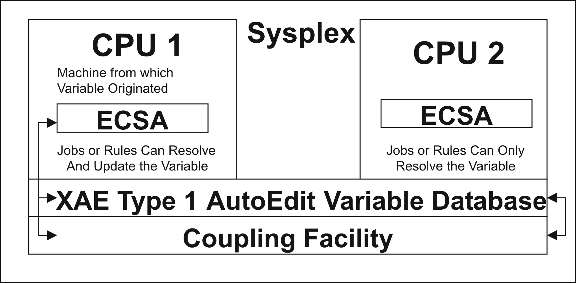
XAE Type 2 Database in a Sysplex
At sites where a Sysplex, an XAE Type 2 database and the Coupling facility are defined, all rules and jobs can access (resolve) and update all AutoEdit variables, regardless of the system on which the AutoEdit variables were originally created.
The following figure shows a XAE Type 2 Database in a Sysplex:
Figure 18 XAE Type 2 Database in a Sysplex
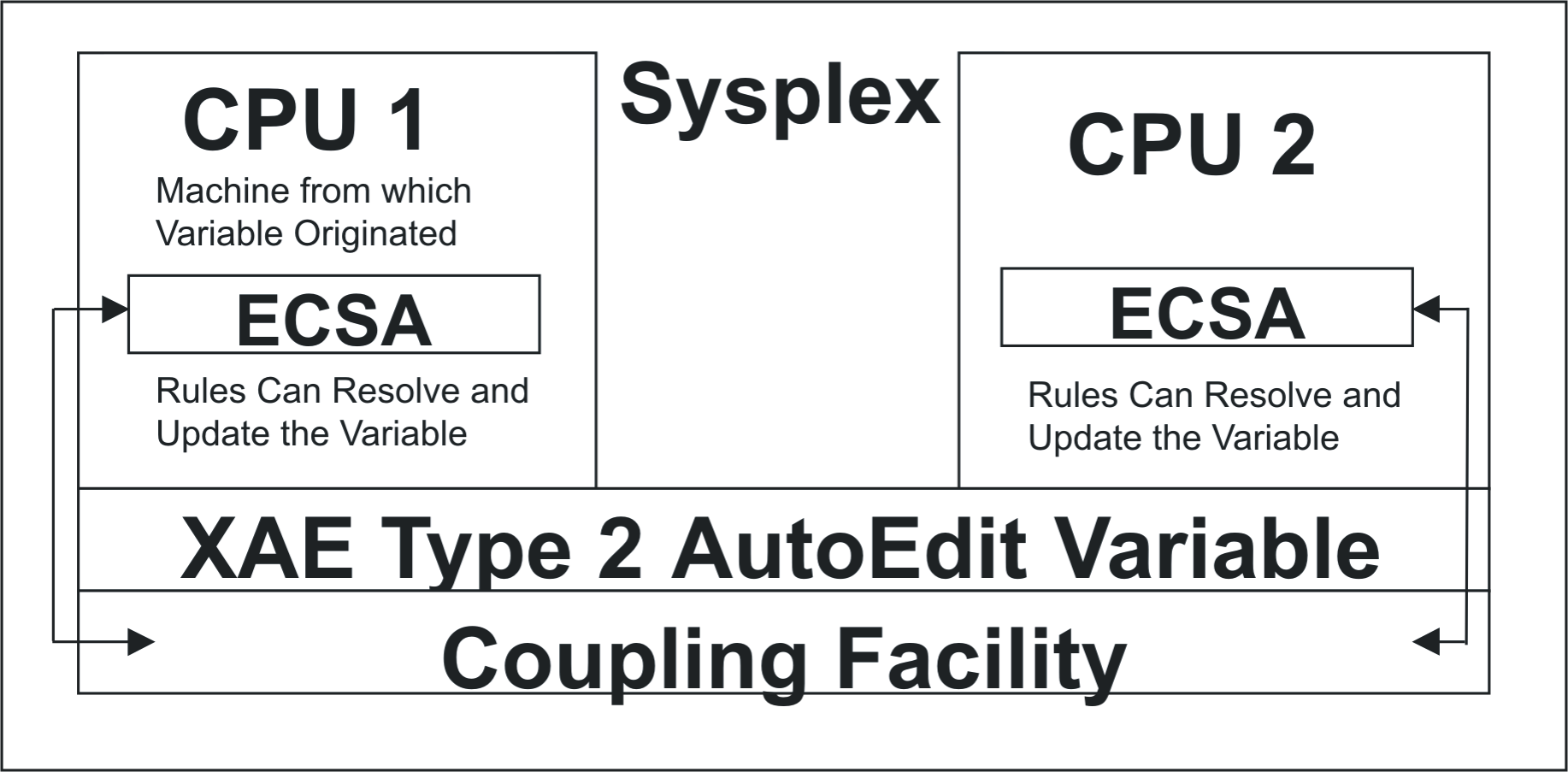
Performance Issues
Running the XAE facility can impact INCONTROL product performance. In some cases, the impact may be negligible. For a description of issues of impact, see Using an XAE Type 1 Database and Using an XAE Type 2 Database.
Using system-managed rebuild or duplexing rebuild for the XAE structures will have the following performance impacts:
-
When the structures are duplexed, each update of a variable updates both copies of the structures.
-
During the system-managed rebuild or duplexing rebuild process, the structures are inaccessible. Requests to access variables will be suspended until the rebuild process ends.
-
If Control-O or CMEM is started or stopped when a system-managed process is performed on its structures, Control-O or CMEM initialization or termination will be suspended until the system-managed process ends and the structures are accessible again.
Using Standard Databases
If you use standard databases to store AutoEdit variables, the variables are stored in the Extended Common Service Area (ECSA) and are resolved based on their current values in ECSA. This option provides the best performance, but does not facilitate direct sharing of variables among Sysplex participants.
Using an XAE Type 1 Database
If you use an XAE Type 1 database to store AutoEdit variables, the variables are stored both in the Extended Common Service Area (ECSA) and using the Coupling facility.
The advantage to this method of storing AutoEdit variables is that resolving the variables from the originating, owning, machine (from ECSA) is not costly in terms of performance.
The disadvantages to this method include the following:
-
More resources are used than when using a standard AutoEdit database. This is because in addition to writing the variable contents to ECSA, the variable has to be updated in a List structure in the Coupling facility.
-
Resolving variables from a machine other than the originating, owning, machine is more costly in terms of performance, because the list in the Coupling facility must be read instead of resolving the value directly from ECSA.
Using an XAE Type 2 Database
If you use an XAE Type 2 database to store AutoEdit variables, the variables are stored both in the Common Service Area (CSA) and using the Coupling facility.
Resolving variables, regardless of from which machine, is always more expensive than with XES Type 1. This is because
-
In the best case scenario, the system checks a directory-only caching mechanism implemented with a lock or cache XES structure pair to know if the ECSA copy of the variable is still valid.
-
In the worst case scenario, the system must both record your interest in that variable, read the Coupling facility for the latest copy and keep that copy in ECSA).
Setting variables, regardless of from which machine, is always more costly than with XES Type 1. This is because, in addition to updating the ECSA, the system
-
updates a directory-only caching mechanism implemented with a lock or cache XES structure pair, to invalidate the ECSA values stored in other computers
-
updates the Coupling facility
Serializing the usage of XAE Type 2 database variables requires that you obtain both per-CPU latches and Sysplex-wide locks that can suspend and delay the execution of an address space. Make sure to avoid the excessive delay of important system address spaces.
Calculating the Disk Space Required for the Variable Database
Installation of the IOA Variable Database is preceded by calculation steps that aid in determining the necessary space for the IO access method files.
The IOA Variable Database facility is composed of three IOA Access Method files (each of which requires two additional files, one for the data component and one for the index component, see IOA Variable Database Facility). Each time you add a new database in the List of Databases screen (of Screen IV) you are actually adding a new record to the Database (DBS) file. Each time you add a new column to an existing database in the List of Columns screen (of Screen IV) you are actually adding a new record to the Column (COL) file. Each time you do one of the following actions, you are actually adding a new record to the Variables (VAR) file:
-
Directly add a new variable to an existing database in the display screen of Screen IV.
-
Indirectly add a new variable to an existing database by executing a WRITEGLOBAL operation, for which a new value for this column/row was not previously defined.
To properly calculate the space required you either need to do one of the following:
-
Estimate the average number of databases, columns and rows for the planned databases, and provide this estimate as input to the calculation steps in ICE.
-
Rely on values obtained empirically from previous releases or experimentation with the facility.
Enlarging IOA Variable Databases
There are different IOA Variable Database types; each is specified in the DAGLBLST concatenation of the Control-O or CMEM monitor. Each database type, shown in the following list, may require different kinds and amounts of resources to provide their respective functionality:
-
DBINOUT
-
DBINPUT
-
DBPROT
-
DBTEMP
-
S1INOUT
-
S1INPUT
-
S1PROT
-
S1TEMP
-
S2INOUT
-
S2INPUT
-
S2PROT
-
S2TEMP
-
When allocating (or enlarging) an IOA Variable Database, you need to know which additional demand you are adding, and on which particular resources or combination of them. This is required to allocate them appropriately. Included among the resources to be considered when preparing to enlarge or allocate an IOA Variable Database are the
-
amount of ECSA needed to store the variables
-
size of the required navigation control structure to the variables
-
amount of ECSA needed for navigation control structures to the variables
-
disk space
-
coupling facility space
Each of these considerations is explained as follows:
-
Calculating the amount of ECSA needed to store the variables.
-
Calculating the size of the required navigation control structure to the variables.
Calculating the amount of ECSA needed to store the variables.
IOA Variable databases are spreadsheet-like matrixes, where the value stored at the intersection of a specific row number and a specific column name (a slot) represents an atomic variable.
ECSA required for a single variable
The amount of ECSA required to store a single atomic variable is 16 bytes of control information, plus the number of characters in the variable column name, plus the number of characters in the value of the variable in that column.
For example, if a variable in the MYCOL column name has 7 characters in its value, that variable will require a total of 28 bytes of ECSA. This total is computed, for purposes of this example, by adding the 16 bytes required for control information, to the 5 characters in the length of MYCOL column name string, plus the number of characters in the value of the variable in that column, which in this example is 7.
The total size of a single variable slot is limited to 256 characters. Therefore, 240 characters is the maximum that the variable name plus the variable value may occupy.
This calculation is the same for all the database types shown below:
-
DBINOUT
-
DBINPUT
-
DBPROT
-
DBTEMP
-
S1INOUT
-
S1INPUT
-
S1PROT
-
S1TEMP
-
S2INOUT
-
S2INPUT
-
S2PROT
-
S2TEMP
ECSA required for all variables in a single IOA Variable database
You can estimate the ECSA required by a single IOA Variable database by calculating the number of columns, multiplied by the number of rows, multiplied by the average size of a variable, as explained above. To this figure, you must add a figure obtained by adding 1 to the number of columns, and multiplying that result by 256.
When calculating the average size, either consider the empty slots as zero length, or do not count them in the average but multiply the (higher) average without the empty slots by a factor < 1, to represent the slot occupancy percentage.
This calculation is the same for all the database types shown below:
-
DBINOUT
-
DBINPUT
-
DBPROT
-
DBTEMP
-
S1INOUT
-
S1INPUT
-
S1PROT
-
S1TEMP
-
S2INOUT
-
S2INPUT
-
S2PROT
-
S2TEMP
ECSA required for all variables in all IOA Variable databases
You can calculate the ECSA requirements for all variables in all IOA Variable databases simply by adding together the ECSA requirements for each individual IOA Variable database.
Calculating the size of the required navigation control structure to the variables.
One of the attributes defined for an IOA Variable database is the NUMBER OF ROWS. The NUMBER OF ROWS is set using the =IV screen, when you add or update a new Variable IOA Database. The NUMBER OF ROWS specified for the IOA Variable Database is the primary input required to calculate the size, in ECSA, of a navigation control structure. The NUMBER OF ROWS attribute enables you to
-
set a limit on the amount of rows that can be added to a database, and indicate an AutoEdit error if that limit is exceeded
-
determine the ECSA space required to allocate a control structure, which helps to easily navigate the databases
This value plays the same role for all the database types shown below:
-
DBINOUT
-
DBINPUT
-
DBPROT
-
DBTEMP
-
S1INOUT
-
S1INPUT
-
S1PROT
-
S1TEMP
-
S2INOUT
-
S2INPUT
-
S2PROT
-
S2TEMP
ECSA required for the control structure of a single IOA Variable Database
The amount of ECSA required to allocate the navigation control structure for a single IOA Variable database is determined by multiplying 16, which is the number of bytes of control information, times the number of rows defined in the database, times the number of columns defined in the database.
This allocation is the same for all the database types shown below:
-
DBINOUT
-
DBINPUT
-
DBPROT
-
DBTEMP
-
S1INOUT
-
S1INPUT
-
S1PROT
-
S1TEMP
-
S2INOUT
-
S2INPUT
-
S2PROT
-
S2TEMP
ECSA required for the control structures of all IOA Variable Databases
You can calculate the ECSA requirements for the control structures of all IOA Variable databases simply by adding together the ECSA requirements of the control structures of each individual IOA Variable database.
Calculating disk space
The database types listed below require disk space for the hardening of the IOA Variable Databases on disk:
-
DBINOUT
-
DBINPUT
-
DBPROT
-
S1INOUT
-
S1INPUT
-
S1PROT
-
S2INOUT
-
S2INPUT
-
S2PROT
The following database types are temporary. They require only ECSA memory, and do not require disk space for the hardening of the IOA Variable Databases on disk.
-
DBTEMP
-
S1TEMP
-
S2TEMP
When disk space is required it can be estimated using the same space calculations discussed in ICE steps 7.1, 7.2, and 7.3 of the IOA installation. The largest consumer of disk space is the Variables file, which is calculated in step 7.3.
Calculating coupling facility space
Different database types require different space allocations. The following table outlines those requirements:
Table 79 Coupling Facility Space Allocation Requirements
|
Database Type |
List Structure Space Required |
Lock Structure Space Required |
Cache Structure Space Required |
Coupling Facility Space Required |
|---|---|---|---|---|
|
DBINOUT |
NO |
NO |
NO |
NO |
|
DBINPUT |
NO |
NO |
NO |
NO |
|
DBPROT |
NO |
NO |
NO |
NO |
|
DBTEMP |
NO |
NO |
NO |
NO |
|
S1INOUT |
YES |
NO |
NO |
YES |
|
S1INPUT |
YES |
NO |
NO |
YES |
|
S1PROT |
YES |
NO |
NO |
YES |
|
S1TEMP |
YES |
NO |
NO |
YES |
|
S2INOUT |
YES |
YES |
YES |
YES |
|
S2INPUT |
YES |
YES |
YES |
YES |
|
S2PROT |
YES |
YES |
YES |
YES |
|
S1TEMP |
YES |
YES |
YES |
YES |
When coupling facility space is required it can be estimated using the same space calculations discussed in ICE step 7.7.
Implementing the increase in size
When you increase the value of the NUMBER OF ROWS attribute you
-
increase ECSA consumption
-
increase the disk space consumption
-
increase the coupling facility space required
Implementing size increases when space was overallocated
However, if the disk space and coupling facility space were overallocated, it is not always necessary to re-allocate them. In such cases, it is enough to issue an F CONTROLO,LOADGLOBAL=xxxxx command in one computer, if the database is a XAE Type 2 database, or in all computers, if the database is Type 1, where xxxxx is the name of the database whose NUMBER OF ROWS has changed.
Updating a database using LOADGLOBAL is hazardous in a live system! For a detailed discussion, see Updating Contents of a Database in Memory.
Implementing size increases when insufficient space was allocated
The following steps outline the procedure for implementing size increases when an insufficient amount of space was originally allocated:
-
To de-allocate the files, bring down the Control-O or CMEM monitor.
-
If more coupling facility space is required, update the CFRM policy and IOAPLEX definitions accordingly, and activate the CFRM policy. For an example of how to execute this process, see ICE steps 7.8 and 7.10. If additional coupling facility space is not required, skip this step.
-
If more disk space is required continue with the next step. Else continue with step 11.
-
Back up your IOA Variable databases.
-
Unload the databases to flat files. To do so, submit jobs IOADBSUL, IOACOLUL, and IOAVARUL from the IOAprefix.JCL library. This creates three sequential files named IOAprefix.FLAT.DBSD, IOAprefix.FLAT.COLD, and IOAprefix.FLAT.VARD respectively.
-
Rename the IOA Access Method files
-
Format the databases using jobs IOADBSBF, IOACOLBF, and IOAVARBF from ICE customization, with the newly calculated size.
-
Load the databases from the flat files using jobs IOADBSLD, IOACOLLD, and IOAVARLD from the IOAprefix.JCL library.
-
Build the indexes with jobs IOADBSBI, IOACOLBI, and IOAVARBI from the IOAprefix.JCL library.
-
Enter Screen IV from the IOA Main Menu, and verify that the databases contain the same data as before.
-
Bring up the Control-O or the CMEM monitors
Expanding Various IOA Files
The following IOA files can be expanded using ICE:
-
IOA Conditions file (CND) (For the procedure, see the IOA file customization section in the INCONTROL for z/OS Installation Guide: Customizing.)
-
IOA Log file (LOG)
-
IOA Manual Conditions file (NRS)
-
IOA Database file (DBS)
-
IOA Columns file (COL)
-
IOA Variable file (VAR)
Perform the following the steps to expand IOA files.
For complete details about the DBS, COL, and VAR files, see Enlarging IOA Variable Databases.
-
Close all monitors and IOA activities.
-
When expanding the IOA Manual Conditions file (NRS), there is no need to close any monitors or IOA activities.
-
When expanding the IOA Variables Database, shut down only CMEM and the ControlO monitors. However, keep in mind that when these monitors are stopped, ControlM is not able to access the AutoEdit variables in the database.
-
-
Rename the old file that you want to expand. If you are expanding the IOA Database, Columns, and/or Variables files, unload the following files to sequential files accordingly:
-
IOADBSUL in IOA.JCL library for the Database file.
-
IOACOLUL in IOA.JCL library for the Columns file.
-
IOAVARUL in IOA.JCL library for the Variables file.
-
-
Delete or Rename the old file that you want to expand. If you are expanding the IOA Variable Database facility’s Columns and/or Variables files, do the following to unload these files to sequential files accordingly:
-
Using ICE, select Customization. Enter IOA in the Product field, select Product Customization, and then select major step2, "Customize Dataset Parameters." Perform the minor steps in order for each file you want to expand.
-
Perform minor step1, "Customization Instructions," which provides an overview of the process.
-
If you are expanding the IOA Log file, perform minor step2, "IOA Log File Space Calculation."
-
-
Perform minor step3, "IOA Dataset Parameters," which lets you specify values that ICE uses to calculate the appropriate file size. During this step, specify a question mark (?) in any parameter field for help.
Modify only the parameters relevant for the files you want to expand. The following table lists parameters that can be changed in this step:
Table 80 Parameters that can be changed in this step
Parameter
Description
Relevant File
CNDREC#
Number of records in the IOA Conditions file
Conditions file
NRSREC#
Number of records per day in the IOA Manual Conditions file
Manual Conditions file
DUALDB
Mirror Database = Y (Yes) or N (No)
Dual Conditions file
-
If you are expanding the IOA Database, Columns and Variables files, perform minor steps4 through 6, respectively.
-
Perform minor step7, "Save Parameters into Product Libraries," to save the parameter values that you specified in minor step3.
-
Minor steps8 through14 are jobs that perform the expansion. Perform only those steps relevant to the files you want to expand.
Table 81 File Expansion Jobs
Files
Job
Parameter Description
Conditions file
FORMCND in the IOA INSTALL library
This job allocates and formats a new Conditions file (CND/CKP) with the new size. If the user has Control‑M installed and is utilizing the Journaling feature, the Journal Conditions file must also be expanded. For details see Expanding Control-M Files.
Log file
FORMLOG in the IOA INSTALL library
This job allocates and formats a new Log file (LOG) with the new size.
Manual Conditions file
FORMNRS in the IOA INSTALL library
This job allocates and formats a new Manual Conditions file (NRS) with the new size.
Databases file
IOADBDBS in the IOA INSTALL library
This job allocates and formats a new Databases file (DBS) with the new size.
Columns file
IOADBCOL in the IOA INSTALL library
This job allocates and formats a new Columns file (COL) with the new size.
Variables file
IOADBVAR in the IOA INSTALL library
This job allocates and formats a new Variables file (VAR) with the new size.
-
Copy the old files into the new ones according to the instructions below:
Table 82 Copy Methods
Files
Copy Method
Conditions file
Copy using utility IOACCND. For information about utility IOACCND, see the INCONTROL for z/OS Utilities Guide.
Log file
Copy using utility IOACPLOG in the IOA JCL library. For information about utility IOACPLOG, see the INCONTROL for z/OS Utilities Guide.
Manual Conditions file
Run utility IOALDNRS to load the manual conditions into the new Manual Conditions (NRS) file.
Databases file
Load sequential file IOADBSLD and build index IOADBSBI into the IOA.JCL library.
Columns file
Load sequential file IOACOLLD and build index IOACOLBI into the IOA.JCL library.
Variables file
Load sequential file IOAVARLD and build index IOAVARBI into the IOA.JCL library.
-
Start the monitors and issue other relevant modify commands.
CMEM-related maintenance
For details on maintaining (adding, deleting, or changing) the CPU list, SMFIDs, JES SIDs, and communication files, see the INCONTROL for z/OS Installation Guide.
IOA Log Index
The IOA Log Index provides direct access to specific records or ranges of records in the IOA Log file.
This feature significantly decreases the number of required I/O operations, thereby saving reading time and CPU.
The IOA Log Index has the following impact on the retrieval of IOA Log messages:
Table 82a IOA Log Index impact
|
Scenario |
Impact |
|---|---|
|
Index not active or log file not indexed |
When getting log messages, all log messages for the specific time period are read serially. |
|
Index is active and log file is indexed |
When getting log messages, only the required log messages are read and then the unindexed log messages (if they exist) are read serially. |
Activating the IOA Log Index
To activate the Log Index, run the IOALOGXC utility once with parameter FUNC=ACT.
After the initial activation, run the IOALOGI utility periodically to build the index.
Note that the IOA Log Index is used only if it is in active status AND its records are indexed.
Checking the status of the IOA Log Index
To check the status of the IOA Log Index, you can use the IOAVERFY utility. Run utility IOAVERFY with parameter VERIFY FILE LOG to print the following details:
-
Status of the IOA Log Index
-
Date and time of the last run of the IOALOGI utility
-
Percent of indexing of the IOA LOG file
Alternatively, the Control-M interface to the IBM Health Checker offers an IOA Log Index File Status check (CTM_<monitorName>_IOALOG_INDEX) that provides you with information about the status of the IOA Log Index.
The following messages are examples of messages returned by the Health Checker:
-
IOA Log Index is not active:
CopyCTMH1BI_HC IOALOG INDEX FILE CONDITION
IOALOG index file current status:
=================================
IOALOG index is not active.
* Medium Severity Exception *
CTMH1DE_HC CURRENT STATUS OF IOALOG INDEX IS "NOT ACTIVE" -
IOA Log Index is active but the log is not sufficiently indexed:
CopyCTMH1BI_HC IOALOG INDEX FILE CONDITION
IOALOG index file current status:
=================================
IOALOG is currently 52.1% indexed.
* Medium Severity Exception *
CTMH1EE_HC CURRENT STATUS OF IOALOG INDEX IS BELOW THRESHOLD OF 85% -
IOA Log Index is active and the log is sufficiently indexed:
CopyCTMH1BI_HC IOALOG INDEX FILE CONDITION
IOALOG index file current status:
=================================
IOALOG is currently 89.9% indexed.
CTMH1CI_HC CURRENT STATUS OF IOALOG INDEX IS "OK"
Problem Determination
Control‑O is supplied with internal debugging (trace) facilities that provide the ability to print an internal debugging trace and to print the contents of Control‑O internal data areas. Under normal circumstances, the trace facilities are dormant. However, if required (that is, if BMC Customer Support has requested debugging information), you can activate the trace facilities by performing the following steps:
Do one of the following:
-
Start a new ControlO monitor with the following operator command:
CopyS CONTROLO,TRACE=levelThe ControlO monitor passes control to the new ControlO monitor and shuts down.
-
Issue the following operator command:
CopyF CONTROLO,TRACE=levelThe required trace level is supplied by BMC Customer Support. It can be any value from 000 to 255 (000 specifies no debugging).
You should not regularly activate ControlO with the TRACE parameter, because a JES problem may cause ControlO to become suspended while waiting for JES.
Debugging information is printed to files referenced by DD statements DATRACE and DADUMP of the ControlO procedure.
-
When you finish your problem determination procedures, start a new ControlO using operator command
CopyS CONTROLOor specify operator command
CopyF CONTROLO,TRACE=00
Internal Trace facility
IOA provides an internal Trace facility that can print internal tracing records and the contents of internal data areas. Under normal circumstances, the Trace facility is dormant. However, if required, that is, if BMC Customer Support has requested tracing information, the Trace facility can be activated.
Use these facilities only when requested by BMC Customer Support.
Tracing can be requested for specific components. Each component has its own identifying numbers for purposes of producing the trace. These numbers are called trace levels. One or more trace levels can be activated at the same time. Trace levels can be modified during execution.
BMC Customer Support provides you with a list of the trace levels that are used, depending on the problem encountered.
Internal tracing can be activated when the monitor is started or during monitor execution, and it can be modified or stopped during monitor execution. The internal trace setting can be displayed.
Activating the internal Trace facility
The IOA Online Monitor and each of the INCONTROL products has its own operator commands that initiate the internal Trace facility. Some products also differentiate between which operator commands are issued, depending on whether the product's monitor is active or inactive. For information on initiating the Trace facility for an INCONTROL product, see the chapter that discusses that product.
For example, to initiate the internal Trace facility in Control‑M, enter the command
F CONTROLM,TRACE=levelSimilarly, to initiate the internal Trace facility for the IOA Online Monitor, enter the command
F IOAOMON,TRACE=levelIn such a command, level is the list of trace levels to be activated or deactivated. Each INCONTROL product has different numbers of levels. For example, the Control‑M Trace facility has 128 levels (that is, from 1 through 128, inclusive).
Numbers are used to activate or deactivate the trace. Positive numbers activate the trace; negative numbers deactivate the trace. Valid level values are
-
any number between 1 and that product's maximum number of levels, or a range of numbers, such as 10:15, to activate the trace. The level is added to the levels already set.
-
any number between -1 and the negative value of that product's maximum number of levels, or a range of numbers, such as-20:-25, to deactivate the trace. The level is removed from the active levels.
The following table gives examples of how to specify the levels that are on or off:
Table 83 Examples of turning Trace levels on and off
|
Level |
Example |
|---|---|
|
x |
Trace level to turn on. TRACE=3 turns on trace level 3. |
|
-x |
Trace level to turn off. TRACE=‑3 turns off trace level 3. |
|
(x:y) |
|
|
Range of trace levels to turn on, where x is the first level in the range and y is the last level in the range. TRACE=(1:10) turns on trace levels 1 through 10. |
|
|
(‑x:‑y) |
Range of trace levels to turn off, where x is the first level in the range and y is the last level in the range. TRACE=(‑1:‑10) turns off trace levels 1 through 10. |
|
(x,y,z,...)
|
Multiple trace levels to turn on. TRACE=(3,5,29) turns on trace levels 3, 5 and 29. |
|
(‑x,‑y,‑z,...) |
Multiple trace levels to turn off. TRACE=(‑3,‑5,‑29) turns off trace levels 3, 5 and 29. |
When the trace level set is completed, the following messages are displayed on the console, along with other product-specific messages (depending on the parameters specified):
IOAD01I TRACE LEVELS SET AS FOLLOWS:
IOAD02I 00nn:00mm – TURNED on or off
Trace facility output
Tracing information is written to one or more of the following locations, depending on which trace levels were turned on:
-
DD statement DATRACE of the INCONTROL product's procedure.
-
DD statement DADUMP of the INCONTROL product's procedure.
-
SYSDATA of the INCONTROL product's started task.
Stopping the internal trace
When you have finished the problem determination procedures, internal tracing is stopped.
Use the following operator command to stop internal tracing in Control‑M:
F CONTROLM,TRACE=(-1:-128)When tracing is stopped, the following messages are displayed on the console, along with any other product-specific messages:
IOAD01I TRACE LEVELS SET AS FOLLOWS:
IOAD02I 0001:1024 – TURNED OFF
Displaying the internal Trace setting
The internal trace setting (level, DBGJOB value, and DBGPIPE value) can be displayed for a specific monitor.
Operator commands exist for each INCONTROL product for displaying the internal trace setting.
Use the following operator command to display the internal trace setting in Control‑M:
F CONTROLM,TRACE=SHOWThe following messages are produced as the result of the SHOW command, along with any other product-specific messages:
IOAD03I PRESENT TRACE LEVELS ARE AS FOLLOWS:
IOAD04I level:level – on or off
IOAD04I level:level – on or off
Identity Level (IDL) facility
The IDL facility is a diagnostic tool that can be used to determine, store, monitor, and display the maintenance level of the INCONTROL code running in an address space. This section describes:
IDL features
The IDL facility includes features that run automatically, and additional features that can be implemented by specific IDL modify commands.
Automatic features
The IDL facility automatically
-
performs level identification of each CSECT of the code running in an address space
-
creates level data snapshots and places them in storage at predefined checkpoints, which makes this data available the moment an address space abends
-
detects level changes between snaps
-
detects changes in address space configuration (list of running tasks) between subsequent snaps
Additional features
With the IDL modify commands (See Modify commands), the IDL facility can be used to
-
perform service functions in order to tune IDL facility behavior (see DABAPI and DUP)
-
change or set a default group ID (see DEFGROUP)
-
display level data of a specific module, modules, CSECT, or CSECTs (see SHOWCSECT and SHOWMODULE)
-
display the level data of a predefined group of modules, as listed in the IOALSUM Summary Table (see SHOWGROUP)
-
display level data (see SHOWLEVEL)
-
perform service functions useful when monitoring an address space or when finding problems (see SHOWMEMORY)
-
display a full list of tasks and modules currently running in an address space (see SHOWMODULES)
-
display modules or CSECTs that cannot be identified (see SHOWSHORT and SHOWUNKNOWN)
-
display level data snapshots (see SHOWSNAP)
-
create level data snapshots and place them in storage by means of a modify command (see SNAP)
Output
The IDL facility provides the following output features:
-
DAPRIDL output – automatically sent, except in specially noted cases, into a dynamically allocated DAPRIDLDDstatement.
-
DABAPI output – If TRACE=499 is set at product start-up, DABAPI output will be activated and IBM Binder API diagnostic messages will be issued. (See DABAPI)
Modify commands
Modify commands supported by the IDL facility are issued using the following syntax:
F <ioagate>,IDL=<modify-command>[=<optional parameter>]In this syntax
-
ioagate – started task name
-
modify-command – specific IDL modify command, listed alphabetically, below
-
optional parameter – optional parameter that may be available for some of the modify commands, described below, where applicable
DABAPI
The DABAPI IDL modify command enables or disables the DABAPI additional diagnostic output file. When enabled, original IBM Binder API diagnostic messages are sent to this output. The DABAPI IDL modify command syntax is:
DABAPI={ENABLE|DISABLE}Shown below is an example of the output of the DABAPI command:
DEFGROUP
The DEFGROUP IDL modify command changes or sets a new group ID of modules that were predefined in the IOALSUM Summary Table. The DEFGROUP IDL modify command syntax is:
DEFGROUP[=<group id>]Shown below is an example of the output of the DEFGROUP command:
IOAL00I IDL FACILITY RECEIVED REQUEST(DEFGROUP=IOA)
IOAL2VI DUPLICATE MODULEs WILL BE IGNORED; DEFAULT GROUP ID(IOA)
IOAL0RI IDL REQUEST(DEFGROUP=IOA)           PROCESSED SUCCESSFULLY
DUP
The DUP IDL modify command enables or disables handling of duplicate modules. When enabled, each instance of a module running in an address space, including those that repeat, is handled by the IDL facility. The DUP IDL modify command syntax is:
DUP= {HANDLE | IGNORE}Shown below is an example of the output of the DUP command:
IOAL2WI HANDLING OF DUPLICATE MODULES HAS BEEN ENABLED
IOAL00I IDL FACILITY RECEIVED REQUEST(DUP=HANDLE)
LISTVDET
The LISTVDET IDL modify command provides you with detailed information about storage memory allocations. The report is issued in the file referred by the DD card DAPRENV.
This command does not require any parameters.
Every allocated block is listed by TCB and subpool number. The following information is displayed on the operator console from which the modify command was issued:
-
TCB
-
SUBPOOL: Subpool number
-
FROMADDRESS: Address from which the dataset is allocated
-
LENGTH: Size of the dataset (both above and below the line)
LISTVSUM
The LISTVSUM IDL modify command provides you with a summary of information about storage memory allocations. The report is issued in the file referred by the DD card DAPRENV.
This command does not require any parameters.
The generated summary storage map lists totals for all allocated blocks.
HELP
The HELP IDL modify command displays a list of IDL modify commands that are available for use. BMC recommends that you use this command as appropriate. The HELP IDL modify command syntax is:
HELPShown below is an example of the output of the HELP command:
SHOWMODULES - SHOW MAP OF THE ADDRESS SPACE
SHOWGROUP   - SHOW IDL INFO ABOUT PRE-DEFINED SUMMARY MODULES
SHOWSNAP    - SHOW CONTENTS OF THE LAST IDL SNAP
HELP        - SHOW LIST OF AVAILABLE MODIFY COMMANDS
SHOWMEMORY= - PRINT MEMORY OR MODULE INTO DATRACE
REFRSUMMARY
The REFRSUMMARY IDL modify command dynamically refreshes the IOALSUM Summary Table. BMC recommends that you use this command as appropriate. The REFRSUMMARY IDL modify command syntax is:
REFRSUMMARYShown below is an example of the output of the REFRSUMMARY command:
IDL FACILITY RECEIVED REQUEST(REFRSUMMARY) SHOWCSECT
The SHOWCSECT (and WTOSECT) IDL modify commands display, in either DAPRIDL or WTO output, respectively, IDL information about a specific CSECT or multiple CSECTs[*]. An asterisk (*) can be used as a mask character when specifying the parameter. The command syntax of the SHOWCSECT and WTOCSECT IDL modify commands is:
SHOWCSECT={<name>|<mask>}
WTOCSECT={<name>|<mask>}
Shown below is an example of the output of the SHOWCSECT command:
IDL FACILITY RECEIVED REQUEST(SHOWCSECT=IOAMR*)
MODULE   CSECT    OFFSET LENGTH DATE         TIME   RELEASE APAR   LNG
-------- -------- ------ ------ --------     -----  ------- ------ ---
IOAMRO   IOAMRO   000000 001A92 02/17/04     14.24  6.2 BI2590 ASM
IDL REQUEST(SHOWCSECT=IOAMR*) PROCESSED SUCCESSFULLY, 01.80 sec CPU used; Items:0001/0918
SHOWFOREIGN
The SHOWFOREIGN IDL modify command displays IDL information about foreign (non-BMC) CSECTs. The SHOWFOREIGN IDL command syntax is:
SHOWFOREIGNShown below is an example of the output of the SHOWFOREIGN command:
MODULE   CSECT    OFFSET LENGTH
-------- -------- ------ ------
ECADCMPR L$C#TRN  004BA8 000008 Foreign             belongs to SAS
ECADCMPR L$CARGS@ 004BB0 000214 Foreign             belongs to SAS
ECADCMPR L$CARGS+ 004E68 000034 Foreign             belongs to SAS
SHOWFULL
The SHOWFULL IDL modify command displays full IDL information about the entire code currently running in an address space, including information about unknown, unidentified, foreign, and short CSECTs. The SHOWFULL IDL command syntax is:
SHOWFULLSHOWGROUP
The SHOWGROUP IDL modify command displays IDL information about a group of modules that were predefined in the IOALSUM Summary Table under the selected group ID. The default group ID is used when no group is given in the modify command, as described in the section on the DEFGROUPcommand. BMC recommends that you use this command as appropriate. The SHOWGROUP IDL command syntax is:
SHOWGROUP[=<group id>]Shown below is an example of the output of the SHOWGROUP command:
IDL FACILITY RECEIVED REQUEST(SHOWGROUP=MCT)
IOAL02I GROUPID: MCT
MODULE   CSECT    OFFSET LENGTH DATE         TIME   RELEASE APAR   LNG FROM
-------- -------- ------ ------ --------     -----  ------- ------ ---  ----
IOAENV   IOAENV   000000 001BD8 11/09/03     13.38  6.2     II0873 ASM (storage)
IOAMRO   IOAMRO   000000 001A92 02/17/04     14.24  6.2     BI2590 ASM
IOAMRO   H2TIMER  001A98 000346 03/21/00     13.27  6.2     IOA600 ASM
IOAPRML  IOAPRML  000000 00304A 04/20/04     21.37  6.2     II0906 ASM (library)
IOAPRML  IOAPRS   003050 001360 03/21/00     13.39  6.2     IOA600 ASM
IOALLOC  IOALLOC  000000 002578 03/30/04     17.52  6.2     II0902 ASM (library)
IOAMIO   IOAMIO   000000 000A3C 11/05/03     11.52  6.2     II0862 ASM (library)
In the rightmost column of the SHOWGROUP output
(storage) means that the IDL facility located this module in an address space
a column with no entry describes an internal CSECT
(library) means that the IDL facility failed to locate this module in an address space to retrieve the level information.
The IDL facility therefore has to load the information from a library and to delete later.
SHOWLEVEL
The SHOWLEVEL (and WTOLEVEL) IDL modify commands display, in either DAPRIDL or WTO output, respectively, level information about the code currently running in an address space. BMC recommends that you use this command as appropriate. The command syntax of the SHOWLEVEL and WTOLEVEL IDL modify commands is:
SHOWLEVEL
WTOLEVEL
Shown below is an example of the output of the SHOWLEVEL command:
IDL FACILITY RECEIVED REQUEST(SHOWLEVEL)
MODULE   CSECT    OFFSET LENGTH DATE         TIME   RELEASE APAR    LNG
-------- -------- ------ ------ --------     -----  ------- ------  ---
ECAGTW   ECAGTW   000000 002B18 04/25/04     17.27  6.2     N03     ASM
ECAGTW   CTMRSV   002B18 000300 03/21/00     13.10  6.2     IOA600  ASM
ECAGTW   CTMXAGR  002E18 000190 03/21/00     12.53  6.2     IOA600  ASM
ECAGTW   IOATRCS  002FA8 001D99 03/21/00     14.05  6.2     IOA600  ASM
ECAGTW   IOADUMP  0053F8 00167D 11/20/00     10.16  6.2     II0610  ASM
ECAGTW   IOAHEX   006A78 000321 03/12/02     19.35  6.2     WD3399  ASM
ECALIDL  ECALIDL  000000 00021C 04/17/04     14.08  6.2     N03     ASM
ECALAST  ECALAST  000000 0031F8 01/11/04     13.13  6.2     BG0232  ASM
SHOWMEMORY
The SHOWMEMORY IDL modify command prints memory, module, or control block information into DATRACE output. Default size is 256 bytes. BMC recommends that you use this command as appropriate. The SHOWMEMORY IDL command syntax is:
SHOWMEMORY= {<module>|<address>|<control block>}[,{size | FULL}]Shown below is an example of the SHOWMEMORY command, followed by DATRACE output:
FACILITY RECEIVED REQUEST(SHOWMEMORY=IOAMRO)
DATRACE output:
SHOWMEMORY=IOAMRO          Address=000371D8 Size=256
000371D8 (+0000) B24000E0 18A118CF 41B00FFF 41BCB001  *   \ ~          *
000371E8 (+0010) 47F0C030 C9D6C1D4 D9D64040 60F0F261  * 0{ IOAMRO  -02/*
000371F8 (+0020) F1F761F0 F460F1F4 4BF2F440 40400700  *17/04-14.24     *
00037208 (+0030) 47F0C0A0 C9D6C1D4 D9D64040 406040F0  * 0{ IOAMRO   - 0*
00037218 (+0040) F261F1F7 61F0F440 F1F44BF2 F4406040  *2/17/04 14.24 - *
00037228 (+0050) C3D6D5E3 D9D6D360 C96B40D9 C5D340F6  *Control-I, REL 6*
The MCT and IDL control blocks are currently supported. If no size is specified for a control block identified by a keyword, its full size is printed.
You can use the ",FULL" keyword for a module. For example, you can print an entire module (subject to a 32,767 byte size limitation) if you enter the SHOWMEMORY=<module name>,FULL command.
SHOWMODULE
The SHOWMODULE (and WTOMODULE) IDL modify commands display, in either DAPRIDL or WTO output, IDL information about a specific module or multiple modules. An asterisk (*) can be used as a mask character when specifying the parameter. The SHOWMODULE and WTOMODULE IDL command syntax is:
SHOWMODULE= {<name>|<mask>}
WTOMODULE= {<name>|<mask>}
Shown below is an example of the output of the SHOWMODULE command:
IDL FACILITY RECEIVED REQUEST(SHOWMODULE=IOAMRO)
MODULE   CSECT    OFFSET LENGTH DATE         TIME   RELEASE APAR   LNG
-------- -------- ------ ------ --------     -----  ------- ------ ---
IOAMRO   IOAMRO   000000 001A92 02/17/04     14.24  6.2     BI2590 ASM
IOAMRO   H2TIMER  001A98 000346 03/21/00     13.27  6.2     IOA600 ASM
IOAMRO   IEANTRT  001DE0 000046 Foreign belongs to IBM
SHOWMODULES
The SHOWMODULES IDL modify command displays a map of an address space, that is, a full list of tasks and modules currently running in an address space. BMC recommends that you use this command as appropriate. The command syntax of the SHOWMODULES IDL modify commands is:
SHOWMODULESShown below is an example of the output of the SHOWMODULES command:
Address Space: A60GATED.A60GATED-GATEWAY(STC20438)  System ID: OS35  OS/390 02.10
Module     TCB    CB  Owner  EPAddrss Length SP  Use Attributes Resident AMODE Alias
--------   ------ --  ------ -------- ------ --- --- ---------- -------- ----- -
IEAVAR00   9FE0A8 RB* OS2.10 879941C8 002420 252 193 Rent     L FLPA >16    31
IEFSD060   9FFBF8 RB         80E57940 00E8C0 000 000 Rent     L PLPA        31
IEESB605   ...    RB* 9FE0A8 00E68000 0049C0 000 000 Rent     L PLPA        24
ECAGTW     9F94C8 RB* 9FFBF8 00007380 01FC80 251 001      AC1 L JPA        ANY
ECALAST    ...    LLE        97532A60 0035A0 251 001      AC1 L JPA  >16    31
ECAXMI     ...    LLE        80034B90 001470 251 001          L JPA         31
SHOWSHORT
The SHOWSHORT IDL modify command displays IDL information about of CSECTs that are too short to be identified. The command syntax of the SHOWSHORT IDL modify commands is:
SHOWSHORTShown below is an example of the output of the SHOWSHORT command:
IDL FACILITY RECEIVED REQUEST(SHOWSHORT)
MODULE   CSECT    OFFSET LENGTH
-------- -------- ------ ------
IOADBSB# IOADBSB# 000000 000010 Short
IOADBIB# IOADBIB# 000000 000010 Short
SHOWSNAP
The SHOWSNAP IDL modify command displays the contents of the last IDL snapshot written into storage. The command syntax of the SHOWSNAP IDL modify commands is:
SHOWSNAPShown below is an example of the output of the SHOWSNAP command:
IDL FACILITY RECEIVED REQUEST(SHOWSNAP)
IDL SNAP data created: 25/04/2004 17:32:07 Mode:DUP  (or NOD)
     TCB:009F94C8
Module   CSECT    Offset Length Created:timestamp Release  APAR
ECAGTW   ECAGTW   000000 002B18 04/25/04    17.27 6.1.12  N03
ECAGTW   CTMRSV   002B18 000300 03/21/00    13.10 6.1.00 IOA600
ECAGTW   CTMXAGR  002E18 000190 03/21/00    12.53 6.1.00 IOA600
ECAGTW   IOATRCS  002FA8 001D99 03/21/00    14.05 6.1.00 IOA600
ECAGTW   IOADUMP  0053F8 00167D 11/20/00    10.16 6.1.02 II0610
ECAGTW   IOAHEX   006A78 000321 03/12/02    19.35 6.1.02 WD3399
ECALAST  ECALAST  000000 0031F8 01/11/04    13.13 6.1.10 BG0232
ECALAST  CTMXAGR  0031F8 000190 03/21/00    12.53 6.1.00 IOA600
SHOWUNIDENT
The SHOWUNIDENT IDL modify command displays IDL information about unidentified, but otherwise known, IDL facility CSECTs. BMC recommends that you use this command as appropriate. The command syntax of the SHOWUNIDENT IDL modify commands is:
SHOWUNIDENTShown below is an example of the output of the SHOWUNIDENT command:
IDL FACILITY RECEIVED REQUEST(SHOWUNIDENT)
MODULE   CSECT    OFFSET LENGTH
-------- -------- ------ ------
ECAGTW   ECAEPARS 004D48 0006B0 Unidentified
ECAGTW   IOAPAR   006DA0 0009A6 Unidentified
ECADCMPR ECANCMP@ 001F40 000380 Unidentified
ECADCMPR ECANCMP+ 0024E8 000034 Unidentified
SHOWUNKNOWN
The SHOWUNKNOWN IDL modify command displays IDL information about objects that are not defined in the table of INCONTROL prefixes, that is, CSECTs that are unknown to the IDL facility. The command syntax of the SHOWUNKNOWN IDL modify commands is:
SHOWUNKNOWNShown below is an example of the output of the SHOWUNKNOWN command:
MODULE   CSECT    OFFSET LENGTH
-------- -------- ------ ------
ECAGTW   WORKAREA 007748 000218 Unknown
ECAGTW   MODIFY   007960 000DB4 Unknown
ECAGTW   SHOWSTAT 00A5B8 0011D7 Unknown
SNAP
The SNAP IDL modify command repairs and writes the IDL snapshot into memory. BMC recommends that you use this command as appropriate. The command syntax of the SHOWUNKNOWN IDL modify commands is:
SNAPShown below is an example of the output of the SNAP command:
IDL FACILITY RECEIVED REQUEST(SNAP)
NEW TASK(ECACMC/9A9448)   STARTED SINCE LAST IDL SNAP(17:32:07-25/04/2004)
257 kb OF IDL DATA SUCCESSFULLY SNAPPED AT(1860E000-22:58:33-25/04/2004) 014.36 sec CPU
WTOCSECT
The WTOCSECT IDL modify command is described as part of SHOWCSECT. An asterisk (*) can be used as a mask character when specifying the parameter.
WTOLEVEL
The WTOLEVEL IDL modify command is described as part of SHOWLEVEL. An asterisk (*) can be used as a mask character when specifying the parameter.
WTOMODULE
The WTOMODULE IDL modify command is described as part of SHOWMODULE. An asterisk (*) can be used as a mask character when specifying the parameter.
External tables
The following external tables affect IDL functionality:
-
IOALIDS – Table of prefixes, owners, and identification strings that resides in a IOA load library
-
IOALSUM – Source summary table that resides in a IOA IOAENV library
The IDL facility can function without reference to any other external parameters.
IOALIDS table
The IOALIDS table of prefixes, owners, and identification strings is the main source upon which functioning of the IDL facility is based, in order to identify the running code. IOALIDS is provided as a load module that cannot be customized by a user.
The table has the following parts:
-
Prefixes of the INCONTROL code
-
Owners of CSECTs
-
Identification strings
IOALSUM table
The IOALSUM IOAENV source member (Summary table) contains a list of groups of modules about which level information can be issued by the SHOWGROUP modify command (see SHOWGROUP). The default group ID can be assigned by the DEFGROUP modify command, as shown in DEFGROUP. If there is a need to update the table it should be copied into the IOA PARM library and changed there. The IOALSUM table can be refreshed dynamically by using the REFRSUMMARY modify command (REFRSUMMARY) without need to recycle an address space.
The following code shows an example of an IOALSUM Summary Table:
Table 84 IOALSUM Summary Table
SUMMARY GROUP=CTO,        DISPLAY=(CTOAIDT,CTOWTO,CTOXCF,CTOAPI,CTOAODT,
        DFSAOE00,IGDACSDC,IGDACSMC,IGDACSSC,DFSAOUE0)

SUMMARY GROUP=CTT,
        DISPLAY=(IOADBS,IOADBI,CTTDBT,CTTSYS,CTTHBLK,CTTCUP,CTTTRC)

SUMMARY GROUP=IOA,
        DISPLAY=(IOAENV,IOAMRO,IOAPRML,IOALLOC,IOAMIO)

SUMMARY GROUP=ECA,
        DISPLAY=(ECAGTW,ECAMBX,ECAAMGR,ECACOMT,ECACMGRP)
Up to 28 modules can be specified in one group. The group ID is an arbitrary three‑character string. At least one IOA group with a unique ID must be coded in the IOALSUM Summary table.
Messages
The following message groups are issued by the IDL facility:
-
Common informative and error messages: IOAL00I- IOAL0ZS, IOAL1ZW, IOAL2XW – IOAL2ZI, IOAL30W
-
Binder API error messages: IOAL10W- IOAL1YW, IOAL31W – IOAL3HW
-
Modify commands description messages: IOAL21I- IOAL2PI
For more information about these messages, see the INCONTROL for z/OS Messages Manual.
IOA systems comparison facilities
BMC provides the following tools to compare members between two IOA environments to find the differences that can point to existing problems or missing corrections (PTFs):
xxxPARM comparison
This service compares xxxPARM members of the same type to find the differences. For example, the service can be used to compare an IOA environment with an IOA production environment, or a backup library with an operational library. Specific changes can then be undone.
To run the service, do one of the following:
-
From ISPF, execute command REXX IOACMPP
-
Execute batch job IOACMPPJ
For more details about the IOACMPP utility, see the INCONTROL for z/OS Utilities Guide.
Modules level comparison
The purpose of the service is to compare the level information of modules presented in two different IOA load data sets from two different systems. The level information is retrieved using the IDL facility. For more information, see Identity Level (IDL) facility.
For more details about the IOACLVLutility, see the INCONTROL for z/OS Utilities Guide.
Structure
The system consists of the following components:
-
IOACLVLG – The job collects the level information of modules presented in an IOA load data set. It calls the IOACLVLG procedure to collect the level information of the compared load data set. The IOAGLVL, SORT, and ICETOOL programs are called by the procedure to generate the report. The output includes the module name, CSECT name, version number, APAR, IOA QNAME, and INSTID. The control variables in the job must be customized by the user. See the section about activating the utility in the description of the IOACLVL utility in the INCONTROL for z/OS Utilities Guide for a detailed description of the control variables, and the IOACLVLG job example for a sample a customized job. The job is located in the IOA SAMPLE library.
-
IOACLVLC – The job compares the level information of modules presented in two different IOA load data sets. It calls the IOACLVLC procedure to compare the module-level information generated by the IOACLVLG job on two compared systems. The SORT and ICETOOL programs are called by the procedure to generate the report. The output includes the module name, CSECT name, version number, APAR, IOA QNAME, and INSTID. The control variables part of the job must be customized by the user. See the section about activating the utility in the description of the IOACLVL utility in the INCONTROL for z/OS Utilities Guide for a detailed description of the control variables, and the IOACLVLC job example for a sample a customized job. The job is located in the IOA SAMPLE library.
-
IOAGLVL – The program generates the level information for all modules in the STEPLIB data set and fills the temporary data set allocated to the DAPRMDF DDname with the parameters for the SORT utility that will be invoked during the following step. The program is called by the IOACLVLG procedure. The output includes the module name, CSECT name, version number, APAR, IOA QANAME, and SETID. The load module of the program is located in the IOA load data set.
-
IOACLVLT – The member contains the control statement for the ICETOOL utility that is invoked by the IOACLVLG procedure, to remove duplicate entries from the output of the IOAGLVL program. The member is located in the IOA PROCLIB data set, and must not be changed by the user.
-
IOACLVLS – The member contains the control statement for the SORT utility that is invoked by the IOACLVLC procedure, to sort and merge the level information of two compared load data sets. The member is located in the IOA PROCLIB data set, and must not be changed by the user.
-
IOACLVLI – The member contains the control statement for the ICETOOL utility that is invoked by the IOACLVLC procedure, to extract the unique entries from the resulting output. The member located in the IOA PROCLIB data set, and must not be changed by the user.
 Communities
 Support Center
 YouTube
 Twitter
 Facebook
 LinkedIn