Online Facilities
This chapter includes the following topics:
Overview of Online Facility
The following pages describe the main features available under the Online facility.
IOA Features
This section discusses the IOA features common to all INCONTROL products.
General IOA Features
General IOA features include:
-
Customization
-
Environment Support
-
Terminal Support
-
Special Character Usage on Terminals
-
Color Support
-
Prefixing
-
Character Masking
Customization (IOA)
IOA screens, constants, messages, colors, commands, and PFKey definitions can be site-modified to adapt them to local needs. For further details, see the INCONTROL for z/OS Installation Guide: Installing.
INCONTROL products can be customized globally, that is, for the whole site, using the INCONTROL Installation and Customization Engine (ICE), according to profile variables defined during installation.
In addition, INCONTROL products can be customized to respond differently to individual users if these profile variables are specified in user profile members.
For example, depending on the setting of a variable in a particular user profile member, upon exit from a screen in which changes have been requested, this INCONTROL product may either perform the requested changes automatically or display a confirmation window before performing the changes.
Customization issues are discussed in the INCONTROL for z/OS Installation Guide: Customizing.
Environment Support
The Online facility can be activated under the following environments:
-
TSO (native)
-
TSO/ISPF
-
ROSCOE/ETSO
-
CICS
-
VTAM
-
IMS/DC
-
IDMS/DC
-
COM-PLETE
Cross memory interfaces (to the Online monitor) are optional under native TSO, TSO/ISPF, and ROSCOE/ETSO. They are always used under the other environments.
There are slight differences in the operation of the Online facility under the different environments. Special notes are provided in this guide where applicable.
Terminal Support
IOA supports the following models of IBM 3270 terminals:
-
Model 2 – 24 lines, 80 columns
-
Model 4 – 43 lines, 80 columns
-
Model 3 – 32 lines, 80 columns
-
Model 5 – 27 lines, 132 columns
When using the IOA online facility under IMS/DC and IDMS/DC, all model types display 24 lines and 80 columns.
IOA adjusts to the screen size in order to use the maximum available data area on the screen.
Special Character Usage on Terminals
In certain cases, special keyboard characters, such as $, #, and @, are assigned special meanings. The characters specified appear on standard American terminals but may not be available on other keyboards. In addition, some special characters on your keyboard may be assigned different hexadecimal values than the ones recognized by IOA. Special keyboard mapping requirements, and a complete discussion of the conventions used in this guide, are shown in Conventions Used in This Guide.
Color Support
When INCONTROL products are activated from a screen with extended seven-color support, they make extensive use of the color attributes of the screen. The concept of management by color is emphasized in INCONTROL screens.
Like all screen attributes, the color attribute for each field is defined externally to the program and can be locally modified by the site.
IOA does not automatically recognize IMS/DC and IDMS/DC terminals as supporting extended color attributes. If your IMS/DC or IDMS/DC terminal supports extended color attributes and you want IOA to recognize this, refer to the INCONTROL for z/OS Administrator Guide for more information.
At this time, IOA does not support extended color attributes under COM-PLETE.
Due to ISPF characteristics, color changes cannot occur in adjacent columns but must be separated by an attribute byte without color, that is, black. Therefore, some IOA screens have a different appearance under ISPF than under other online environments, such as native TSO and CICS.
Prefixing
For fields that automatically support prefixing, selection strings are always treated as prefixes. Selection is made if a segment of the text beginning with the first letter, that is, any prefix, matches the selection criteria.
Assume the following names exist: A3, A4, M, M01, M03, M12, M13, M22, M23, M30, M33, M103, M135, M301.
Table 16 Prefixing Examples
|
Entry |
Matching Value |
|---|---|
|
Blank |
All of the above values |
|
A |
A3, A4 |
|
M |
M, M01, M03, M12, M13, M22, M23, M30, M33, M103, M135, M301 |
|
M1 |
M12, M13, M103, M135 |
|
M13 |
M13, M135 |
If a field supports prefixing, this fact is indicated in its description.
Character Masking
For fields that support masking, mask characters function as follows:
-
* represents any number of characters, including no characters
-
? represents any one character
For fields that do not automatically support prefixing, a prefix value can be specified by ending the selection string with an asterisk.
Assume the following names exist: A3, M, M3, M01, M03, M13, M23, M33, M103, M435, M2243.
Table 17 Masking Examples
|
Entry |
Matching values |
|---|---|
|
* |
All the above values |
|
M?3 |
M03, M13, M23, M33 |
|
M?3* |
M03, M13, M23, M33, M435 |
|
M??3 |
M103 |
|
M*3 |
M3, M03, M13, M23, M33, M103, M2243 |
|
M* |
M, M3, M01, M03, M13, M23, M33, M103, M435, M2243 Since the last character in this example is *, M is treated as a prefix. |
If a field supports masking, this fact is indicated in its description.
IOA Entry Panel
Enter the IOA Online facility according to the instructions of your INCONTROL administrator. Upon entering the IOA Online facility, the IOA entry panel may be displayed.
Display of the IOA Entry Panel is optional. If your INCONTROL administrator determined that the entry panel is bypassed, the IOA Primary Option menu, which is discussed in the following section, is displayed.
Figure 2 IOA Entry Panel
 ---------------------------  IOA ENTRY PANEL  -------------------------------


         +-----------------------------------------------------------+
         |                                                           |
         |          USER ID      ===>                                |
         |                                                           |
         |          PASSWORD     ===>                                |
         |                                                           |
         |          NEW PASSWORD ===>           ===>                 |
         |                                                           |
         +-----------------------------------------------------------+


      PLEASE FILL IN USER ID AND PASSWORD AND PRESS ENTER             18.30.18
Type your user ID and password and press Enter. If you enter a correct user ID and password, the IOA Primary Option menu is displayed.
The IOA Online facility allows three attempts to enter a valid user ID and password combination. After the third unsuccessful attempt, the program is terminated.
To change a password, type the new password twice: Once in the NEW PASSWORD field and once in the confirmation field to the right of the NEW PASSWORD field.
IOA Primary Option Menu
The IOA Primary Option menu is the primary interface to functions available under the various INCONTROL products. The options displayed in the menu depend on the INCONTROL products installed at the site, and the functions and facilities that have been authorized to you.
Entering =1 in the command line of any other screen returns you to the IOA Primary Option Menu that is displayed at your site.
If only Control-M is installed at your site, and you are authorized to access all functions and facilities, the following screen is displayed:
Figure 3 IOA Primary Option Menu Where Only Control-M Is Installed
---------------------       IOA PRIMARY OPTION MENU       ------------------(1)
OPTION ===>                                               USER        N22A
                                                          DATE        19.08.18


  2   JOB SCHEDULE DEF      CTM Job Scheduling Definition
  3   ACTIVE ENV.           CTM Active Environment Display
  4   COND/RES              IOA Conditions/Resources Display
  5   LOG                   IOA Log Display
  6   TSO                   Enter TSO Command
  7   MANUAL COND           IOA Manual Conditions Display
  8   CALENDAR DEF          IOA Calendar Definition
 IV   VARIABLE DATABASE     IOA Variable Database Definition Facility
  C   CMEM DEFINITION       CTM Event Manager Rule Definition
  W   WORKLOAD MANAGEMENT   CTM Workload Management


COMMANDS:  X - EXIT, HELP, INFO, SET  OR CHOOSE A MENU OPTION          17.59.32
To select an option, type the option number or letters in the OPTION field and press Enter. Alternatively, for a number option, press the PFKey with the same number. For example, to select the LOG option, press PF05/PF17.
Your INCONTROL administrator can limit the options displayed on a user-by-user basis, and can alter option numbers and customize option descriptions. Product-supplied default options are discussed in this guide.
Certain IOA commands, functions, and facilities (options) are shared by all INCONTROL products. These shared IOA commands, functions and facilities are described later in this chapter, and outlined in Table 18.
Table 18 INCONTROL Shared IOA Functions and Facilities
|
Option |
Function |
Description |
|---|---|---|
|
4 |
COND/RES |
Display and update the status of the IOA Conditions file and the Control-M Resources file. |
|
5 |
LOG |
View audit trail information about jobs, missions, and rules scheduled under the supervision of INCONTROL products. |
|
6 |
TSO |
Perform TSO commands. If the Online facility is activated as an ISPF application, this option is displayed as UTILITIES, and it activates the IOA Online utilities under ISPF. If the Online facility is not activated under TSO or TSO/ISPF, option 6 is inactive. |
|
7 |
MANUAL COND |
Display the list of prerequisite conditions that must be confirmed manually by operations personnel. |
|
8 |
CALENDAR DEF |
Define scheduling calendars. |
|
IV |
VARIABLE DATABASE |
Define, display, and update IOA Database variables. This option is available only if Control-M or Control-O is installed. |
|
X |
EXIT |
Exit the Online facility. |
|
INFO |
INFO |
Display a window of information about installed INCONTROL products. For more details on the information displayed by this command, see IOA Version Information. |
|
SET |
SET |
Displays the IOA Set Command Panel, enabling you to set and stop TRACE levels, choose the language that is used in online screens, and to set the representation of special characters ($ and \) that will be used in online screens. For more details, see IOA SET Command Panel. |
The following commands, functions, and facilities (options) are applicable to Control-M:
Table 19 Control-M Functions and Facilities
|
Option |
Function |
Description |
|---|---|---|
|
2 |
JOB SCHEDULE DEF |
Define and modify job production parameters. |
|
3 |
JOB STATUS |
Display and update status of jobs scheduled under Control-M. |
|
C |
CMEM DEFINITION |
Define and modify CMEM rules. |
|
W |
WORKLOAD MANAGEMENT |
Define and modify Workload Policies and Load-Indexes. |
The following IOA Primary Option menu is displayed at sites supporting all currently available INCONTROL mainframe products.
Figure 4 IOA Primary Option Menu When All INCONTROL Products Are Installed
---------------------       IOA PRIMARY OPTION MENU       ------------------(1)
OPTION ===>                                               USER        N06

IOA                        Control-D/V                Control-O

  4  COND/RES                A  MISSION STATUS         OR  RULE DEFINITION
  5  LOG                     M  MISSION DEF            OM  MSG STATISTICS
  6  TSO                     R  REPORT DEF             OS  RULE STATUS
  7  MANUAL COND             T  RECIPIENT TREE         OL  AUTOMATION LOG
  8  CALENDAR DEF            U  USER REPORTS           OA  AUTOMATION OPTS
 IV  VARIABLE DATABASE       F  PC PACKET STATUS       OC  COSMOS STATUS
                            DO  OBJECTS                OK  KOA RECORDER


Control-M & CTM/Restart    Control-M/Analyzer         Control-M/Tape
& Control-M/JCL Verify
  2  JOB SCHEDULE DEF       BB  BALANCING STATUS       TR  RULE DEFINITION
  3  ACTIVE ENV.            BM  MISSION DEF            TP  POOL DEFINITION
  C  CMEM DEFINITION        BV  DB VARIABLE DEF        TV  VAULT DEFINITION
  W  WORKLOAD MANAGEMENT    BR  RULE DEFINITION        TI  INQ/UPD MEDIA DB
 JD  JCL VERIFY DEFAULTS    BA  RULE ACTIVITY          TC  CHECK IN EXT VOL
 JV  JCL VERIFICATION
 JR  JCL VERIFY RULES


COMMANDS:  X - EXIT, HELP, INFO, SET  OR CHOOSE A MENU OPTION          16.20.21
Additional options that are available on the IOA Primary Option Menu only when additional INCONTROL products are installed are listed in the following series of tables. For a description of the options for other INCONTROL products, see the user guides of the respective products.
Table 20 Control-M JCL Verify Functions and Facilities
|
Option |
Name |
Description |
|---|---|---|
|
JD |
JCL VERIFY DEFAULTS |
Adjust the verification criteria settings or accept the current ones. The default settings are specified in the CTJPARM member. |
|
JV |
JCL VERIFICATION |
Activate the JCL verification, reformatting, or enforcement process on job members. |
|
JR |
JCL VERIFY RULES |
Define rules for site standard verification, reformatting, or enforcement. |
Table 20a Control-D and Control-V Functions and Facilities
|
Option |
Name |
Description |
|---|---|---|
|
A |
MISSION STATUS |
Display and update active mission status. |
|
M |
MISSION DEF |
Define migration, printing, backup, and restore missions. |
|
R |
REPORT DEF |
Define decollating missions (including indexing). |
|
T |
RECIPIENT TREE |
Display and update the recipient tree. |
|
U |
USER REPORTS |
Display and update the status of user reports. View reports online. |
|
F |
PC PACKET STATUS |
Display the status of reports (packets) scheduled for transfer from the mainframe to a PC. |
|
DO |
OBJECTS |
Manage Control-D objects. |
Table 20b Control-M/Analyzer Functions and Facilities
|
Option |
Name |
Description |
|---|---|---|
|
BB |
BALANCING STATUS |
Display and update the status of active balancing missions. |
|
BM |
MISSION DEF |
Define balancing missions. |
|
BV |
DB VARIABLE DEF |
Define, display and update Database variables. |
|
BR |
RULE DEFINITION |
Define balancing rules. |
|
BA |
RULE ACTIVITY |
Display rule activity and the result of invoking Control-M/Analyzer rules. |
Table 20c Control-O Functions and Facilities
|
Option |
Name |
Description |
|---|---|---|
|
OR |
RULE DEFINITION |
Define rules. |
|
OM |
MSG STATISTICS |
View message statistics. |
|
OS |
RULE STATUS |
View the Rule Status screen. |
|
OL |
AUTOMATION LOG |
Display commands, messages and/or traces. |
|
OA |
AUTOMATION OPTS |
Display available operator productivity tools. |
|
OC |
COSMOS STATUS |
Display or modify the status of COSMOS-controlled objects and databases. |
|
OK |
KOA RECORDER |
Record VTAM scripts. This option is available only under IOATSO, and not under IOAISPF or IOAMON. |
Table 20d Control-M/Tape Functions and Facilities
|
Option |
Name |
Description |
|---|---|---|
|
TR |
RULE DEFINITION |
Define rules. |
|
TP |
POOL DEFINITION |
Define pools. |
|
TV |
VAULT DEFINITION |
Define vaults. |
|
TI |
INQ/UPD MEDIA DB |
Display the Inquire/Update screen. |
|
TC |
CHECK IN EXT VOL |
Check in external volumes. |
IOA Version Information
Enter INFO (or I) in the OPTION field of the IOA Primary Option menu to display the IOA Version Information window, as illustrated in Figure 5.
The Information window provides the following basic information about the installed INCONTROL products:
-
Name of each product or component
-
Compatibility mode version of the product, as set during installation or upgrade
-
Security status, whether Active or Inactive
In addition, the following basic system information is displayed:
-
The unique IOA QNAME of the current environment
-
IOA TRAN-ID
-
Security Product name
-
Logged-on USER-ID
-
User-selected language
-
OS type and version
-
System SMF-ID, name, and date
-
CPU ID
To exit the Information window and return to the IOA Primary Option menu, press Enter or END (PF03/PF15).
Figure 5 IOA Version Information
 ---------------------       IOA PRIMARY OPTION MENU       ------------------(1)
 OPTION ===>                                               USER        U05
       +------------------------------------------------------------------+
 IOA   |          IOA Version  9.0.18.100  Information and Status         |
       |                                                                  |
   4  C|                           Running Mode Security                  |
   5  L|    IOA                       9.0.18    Active                    |
   6  U|    CDAM                      9.0                                 |
   7  M|    IOAGATE                   9.0.18                              |
   8  C|    CONTROL-M                 9.0.18    Active                    |
  IV  V|    CONTROL-M/Restart         9.0                                 |
       |    Control-M JCL Verify      9.0                                 |
       |    CONTROL-M/Analyzer        9.0       Active                    |
       |    CONTROL-M/Tape            9.0       Active                    |
 Contro|    CONTROL-D                 9.0.18    Active                    |
 & Cont|    CONTROL-V                 9.0                                 |
   2  J|    CONTROL-O                 9.0       Active                    |
   3  A|                                                                  |
   C  C|    IOA QNAME  IOAR900   TRAN-ID            Sec.Prod. RACF        |N
   W  W|    USER-ID    U05       LANGUAGE ENG       OS  z/OS    02.01.00  |B
  JD  J|    SMF-ID     MVS8      SYSTEM NAME  MVS8                        |L
  JV  J|    DATE       14.06.18  CPUID 02CE07 2965                        |
  JR  J|                                                                  |
       +------------------------------------------------------------------+


 COMMANDS: X - EXIT, HELP, INFO, SET OR CHOOSE A MENU OPTION            13.53.32
Multi-Screen Control
It is not necessary to return to the IOA Primary Option menu to move from one online facility to another.
To speed up transfer of control between screens of different facilities and to enable you to manage several online facilities at the same time, transfer control commands can be specified. Transfer commands take you directly from your current screen to the requested screen. Transfer commands can be used to reach any screen that can be accessed by the IOA Primary Option menu at your site.
Each transfer control command consists of an equal sign immediately followed by one of the options of the IOA Primary Option menu, which represents the target screen of the transfer. For example, from any screen, enter:
Table 21 IOA Transfer Control Commands
|
Command |
Description |
|---|---|
|
=5 |
to access the IOA Log screen |
|
=4 |
to access the IOA Conditions/Resources screen |
|
=1 |
to access the IOA Primary Option menu |
If you use a transfer command to reach another screen, the state of the current screen remains unchanged when you return to it by another transfer command.
The INCONTROL administrator can globally deactivate any or all of the transfer commands.
Fast Exit from the IOA Online Facility
To exit immediately from the IOA Online facility, type =X on the command line and press Enter.
In most cases, the =X command has the same effect as pressing END (PF03/PF15) in all open screens and then entering X (Exit) in the IOA Primary Option menu. Any window, such as the Exit Option window, that would be displayed when exiting an open screen is displayed when the =X command is entered.
However, when the =X command is entered while definition screens such as the Calendar Definition screen are open, changes to the open definition screens are cancelled. Changes currently in definition facility list screens, for example, changes to previously closed definition screens, are not cancelled. Those screens and all other open screens are treated as if END (PF03/PF15) has been entered.
The =X command is intentionally not supported on certain screens.
Screen Layout
Most IOA screens are divided into four basic areas. The example used in this section is the IOA Log screen.
Table 22 Basic IOA Screen Areas
|
Screen Area |
Description |
|---|---|
|
Screen Description and Message Line |
This line at the top of the screen describes the purpose of the screen (in the example screen, "IOA Log"). A screen identifier may appear in the upper right corner (in the example screen, 5). This line is also used to display messages. |
|
Screen Header and Command Area |
This area is used for online commands, and, where applicable, headings of the screen data. |
|
Data Area |
On some screens, the data area can be scrolled. For more information, see Scrolling Commands. |
|
Screen Bottom |
This area of the screen usually contains a list of available commands or options (In the example screen, SHOW, TABLE, CATEGORY, and SHPF), or a brief explanation about screen usage. The current time is displayed in the lower right corner. |
Figure 6 IOA Log Screen
FILTER:            ---------------- IOA LOG  -------------------------------(5)
COMMAND ===>                                                    SCROLL===> CRSR
SHOW LIMIT ON ==>                                          DATE 291201 - 010102
DATE   TIME   ODATE  USERID   CODE    ------ M E S S A G E --------------------
311201 184915 311201 K48      SUB13AI JOB K48RUN1 / OID=005W9 SUBMITTER STARTED
                                       PROCESSING JOB ON SYSTEM: OS35
311201 184915 311201 K48      SUB133I JOB K48RUN1 K48RUN /27255 OID=005W9
                                      SUBMITTED FROM LIBRARY (P) K48.LIB.JOB
311201 184918 311201 K48      SPY28GI JOB K48RUN1 K48RUN /27255 OID=005W9 TAPE
                                      DRIVE UNITS USED=00 00
311201 184918 311201 K48      SPY281I JOB K48RUN1 K48RUN /27255 OID=005W9 START
                                       01365.1849 STOP 01365.1849 CPU 0MIN
                                      00.05SEC SRB 0MIN 00.00SEC 0.00 4AOS35
311201 184918 311201 K48      SPY254I JOB K48RUN1 K48RUN /27255 OID=005W9
                                      SCANNED
311201 184918 311201 K48      SEL216W JOB K48RUN1 K48RUN /27255 OID=005W9
                                      UNEXPLAINED COND CODE 0015 STEP EXEC /
311201 184918 311201 K48      SEL214I JOB K48RUN1 K48RUN /27255 OID=005W9 RERUN
                                       NEEDED
311201 184918 311201 K48      SEL205I JOB K48RUN1 K48RUN /27255 OID=005W9 RERUN
                                       IN PROCESS USING MEM K48RUN1
311201 184918 311201 K48      SEL286I JOB K48RUN1 K48RUN /27255 OID=005W9
                                      WAITING FOR CONFIRMATION
CMDS: SHOW, table, CATEGORY, SHPF                                      08.57.11
Commands and PFKeys
Commands are entered by typing a command in the COMMAND field and then pressing Enter, or by pressing a predefined PFKey, or a combination of both.
It is not necessary to enter the full command name; the shortest unique abbreviation of the command is sufficient. If the abbreviation is ambiguous, an appropriate message is displayed in the message area.
IOA commands are flexible; you can change command syntax or provide aliases (synonyms) to suit your site. If you want to add or change a command syntax, consult BMC Customer Support. The examples provided in this chapter exhibit the original command syntax supplied with this INCONTROL product.
PFKey command assignments can be site-customized. It is possible to assign PFKeys differently for each screen. To change PFKey command assignments, see your INCONTROL administrator.
Supplied PFKey definitions are consistent throughout most of the screens. For example: PF08/PF20 is used to scroll down (forward) on all INCONTROL screens where scrolling is possible.
Table 23 Common PFKey Definitions
|
PFKey |
Description |
|---|---|
|
PF01/PF13 |
HELP |
|
PF02/PF14 |
SHOW (where applicable) When the IOA Online facility is activated in ISPF mode (as an ISPF application), PF02/PF14 are usually assigned the ISPF SPLIT command. For more information, see IOA Under ISPF. |
|
PF03/PF15 |
END – exit current screen and go back one level |
|
PF04/PF16 |
RESET (where applicable) |
|
PF05/PF17 |
FIND (where applicable) |
|
PF06/PF18 |
=6 – transfer to TSO screen/application or to UTILITIES screen Disabled under ROSCOE/ETSO, CICS, VTAM, IMS/DC, IDMS/DC, COM-PLETE, and TSO cross memory option. |
|
PF07/PF19 |
UP – scroll backward |
|
PF08/PF20 |
DOWN – scroll forward |
|
PF10/PF22 |
LEFT or PREV (where applicable) |
|
PF11/PF23 |
RIGHT or NEXT (where applicable) |
|
PF12 |
RETRIEVE – retrieves a sequence of commands and options entered by the user during the current session. These commands and options are displayed in reverse order on the command line of the current screen. |
|
PF24 |
SHPF |
To see the PFKey assignment of the screen with which you are working, type reserved command SHPF in the command line and press Enter. A window describing the current PFKey assignment appears on the screen. Press Enter again to close the window.
Figure 7 PFKey Assignment Window
FILTER:            ---------------- IOA LOG  -------------------------------(5)
COMMAND ===>                                                    SCROLL===> CRSR
SHOW LIMIT ON ==>                                          DATE 291201 - 010102
DATE   TIME   ODATE  USERID   CODE    ------ M E S S A G E --------------------
311201 184915 311201 K48      SUB13AI JOB K48RUN1 / OID=005W9 SUBMITTER STARTED
                                       PROCESSING JOB ON SYSTEM: OS35
311201 184915 311201 K48      SUB133I JOB K48RUN1 K48RUN /27255 OID=005W9
                                      SUBMITTED FROM LIBRARY (P) K48.LIB.JOB
311201 184918 311201 K48      SPY28GI JOB K48RUN1 K48RUN /27255 OID=005W9 TAPE
                                      DRIVE UNITS USED=00 00
311201 184918 311201 K48      SPY281I JOB K48RUN1 K48RUN /27255 OID=005W9 START
+----------------------------------------------------------------------------+
|                                                                            |
|     ENTER ENTER                     PF13  HELP                             |
|     PF01  HELP                      PF14  SHOW                             |
|     PF02  SHOW                      PF15  END                              |
|     PF03  END                       PF16  RESET                            |
|     PF04  RESET                     PF17  FIND                             |
|     PF05  FIND                      PF18  =6                               |
|     PF06  =6                        PF19  UP                               |
|     PF07  UP                        PF20  DOWN                             |
|     PF08  DOWN                      PF24  SHPF                             |
|     PF12  RETRIEVE                                                         |
+----------------------------------------------------------------------------+
If you type text in the COMMAND field and press a PFKey, the text in the COMMAND field is treated as a subparameter of the command assigned to the PFKey.
Two additional key definitions are:
Table 24 Additional Key Assignments
|
Key |
Description |
|---|---|
|
PA1 |
ABORT – forced exit If you press PA1 while in AutoRefresh mode (described in AutoRefresh Mode), AutoRefresh mode is canceled. |
|
PA2 |
Under native TSO and ROSCOE, the first time you press this key, the screen is refreshed. The second consecutive time, a copy of the screen is sent to be printed, or to a file, using a PRTDBG DD statement. For terminal models supporting PA3, the PA3 key is defined in exactly the same way as PA2. When the IOA online facility is activated as an ISPF application, PA2 is controlled by ISPF, and only refreshes the screen. To print the screen, see IOA Under ISPF. Under other online environments, such as CICS and VTAM, PA2 serves as a refresh only. Usually one of the PA keys is assigned a local print function. |
For information on changing IOA PFKey definitions, see the appendix in the INCONTROL for z/OS Administrator Guide, which deals with modifying IOA Online Facility Commands.
Scrolling Commands
Scrolling conventions are very similar to the ISPF conventions of IBM. Two basic commands are used for scrolling:
Table 25 Scrolling Commands
|
Command |
PFKey |
Description |
|---|---|---|
|
UP |
(PF07/PF19) |
Scroll up (backward) |
|
DOWN |
(PF08/PF20) |
Scroll down (forward) |
The commands can be entered by typing the command in the COMMAND field or by pressing the predefined PFKey.
The scrolling amount is determined by the content of the SCROLL field in the right corner of the screen header. Valid scrolling amounts are:
Table 26 Scrolling Amounts in the SCROLL Field
|
Scrolling Amount |
Description |
|---|---|
|
PAGE |
Scroll a full page. |
|
HALF |
Scroll a half page. |
|
CRSR |
Scroll by cursor position. If the cursor is outside the data area, a full page is scrolled. |
|
MAX |
Scroll maximum available; for example, UP MAX scrolls to the top. |
It is only necessary to type the first letter of the new amount in the SCROLL field in order to change the scrolling amount.
A scrolling amount other than that shown in the SCROLL field can be used by entering the amount directly after the scroll command itself, or by entering the scroll amount in the COMMAND field and pressing the appropriate scrolling PFKey. The scrolling amount in the SCROLL field remains unchanged.
If PAGE is the value in the SCROLL field, to scroll to the bottom, type M (MAX) in the COMMAND field and press PF08 (DOWN).
LOCATE Command
The LOCATE command, and its abbreviation, L, can be used to search for items in the NAME field in all "directory type" screens that contain scrollable data, such as the Calendar List screen. The syntax of the command is
LOCATE string
where string is the search string. Apostrophes (‘single quotes’) or quotation marks ("double quotes") are not required.
The search proceeds from the top of the list to the first item in the list that starts with the specified string. The cursor is positioned on the OPTION field at the beginning of the line containing the string, if found, or on the OPTION field of the alphabetically closest preceding value if the specified value is not found.
FIND Command
The FIND command, and its abbreviation, F, can be used in all screens that contain scrollable data to find and display the next occurrence of a character string. The syntax of the command is
FIND string [fromcol] [tocol] [PREV]where:
-
string is the search string
Mandatory. -
fromcol is the first column in the search range
Optional. -
tocol is the last column in the search range
Optional. -
PREV is the indicator that the search must move backward, instead of forward, from the current cursor position
Optional.
General Rules
If the string contains blanks, enclose the string with apostrophes (‘single quotes’) or quotation marks ("double quotes"). For example:
FIND 'WAIT SCHEDULE'The column range searched can be limited by entering fromcol or tocol values, or by entering both fromcol and tocol values.
The search for the string proceeds from the current cursor position forward, or backward if PREV is entered. If the string is found, the cursor is positioned at the start of the string.
To repeat the find, to the next or previous occurrence of the string, press PF05/PF17.
The following situations outline where the FIND command can, or should, be further modified to enhance its functionality.
-
Some screens enable the user to limit the number of lines searched by a FIND command. This is discussed in the relevant screen descriptions.
-
In some screens, the FIND command does not detect information that is to the right or left of the information displayed in the monitor. To ensure detection of the desired string, the screen must be displayed in wraparound mode, when available, before executing the FIND command.
Text String Searches
The FIND command can also be used to search for text strings, in which case the command will find all instances of the string, regardless of whether the characters within the string are lowercase, uppercase, or mixed case. To search for a text string, include the letter T immediately before a quoted string.
FIND T'WAIT SCHEDULE'will find WAIT SCHEDULE, and it will also find wait schedule, and Wait Schedule, and any other case variant.
Text string searches are the default. If your system default is for text strings, You do not need to include the T if you perform a text string search. Your INCONTROL administrator can change the default to character string. In this case you do not need to include the C if you perform a character string search.
Character String Searches
The FIND command can be used to search for character strings, in which case the command will find all instances of the string, but only where the string contains characters that match the case specified. To search for a character string, include the letter C immediately before a quoted string.
FIND C'WAIT SCHEDULE'will find WAIT SCHEDULE, but it will not find wait schedule, or Wait Schedule, or any other case variant.
CANCEL and RESET Commands
CANCEL and RESET commands are entered in the COMMAND field.
The CANCEL command cancels changes made in a definition screen, such as the IOA Calendar Definition screen, and exits the screen.
The RESET command (PF04/PF16) cancels Edit environment options specified in a definition screen. It does not cancel changes already made and it does not exit the screen or cancel Edit environment mode. For more information about the Edit environment, see A The Control-M Application Program Interface. The RESET command (PF04/PF16) can also be used in most windows, for example, the Show Screen Filter window, to cancel changes and close the window.
Online Help
The following types of online help are available for INCONTROL screens:
Screen help
Provides information about the entire screen. This help is available on all INCONTROL screens and is accessed by pressing the HELP key (PF01/PF13) while the cursor is positioned on the COMMAND field in the screen.
Line-Sensitive Help
Provides information about the fields on a particular line on a screen. This help is available on several INCONTROL screens. It is accessed by pressing the HELP key (PF01/PF13) while the cursor is positioned on the desired line of the screen.
If line-sensitive help is not supported in a screen, pressing the HELP key (PF01/PF13) from anywhere in the screen displays the beginning of the Help panel.
Figure 8 IOA Help Screen
------------------------------ IOA HELP SCREEN --------------------- (CTMHDT2 )
  COMMAND ===>                                                    SCROLL===> CRSR

  Calendar List Screen
  ====================

  The Calendar List screen displays a list of calendars (members) in the
  specified library. This screen can be entered directly from the entry
  panel or upon exiting the Year List screen.

  By default, only calendar names are listed in the screen. However, if
  the default has been modified at time of installation, statistical
  information is displayed for each calendar name.

  Use the scrolling PFKeys to scroll forward (PF08/PF20) and backward
  (PF07/PF19) on the Calendar List.

  To return to the entry panel, press END (PF03/PF15).


  Options of the Calendar List Screen
  -----------------------------------
  To request one of the following options, specify the option in the OPT
ENTER END OR PF03/PF15 TO EXIT THE HELP SCREEN                         08.55.40
Help can be scrolled using standard scrolling conventions.
To return to the original screen, use the END command (PF03/PF15).
The Help member name appears on the right in the Help screen header. Members containing the Help descriptions can be found in the IOA MSG library.
AutoRefresh Mode
Certain INCONTROL screens, as noted in this chapter where appropriate, support AutoRefresh mode. A screen display in AutoRefresh mode is automatically updated periodically with the most current data.
AutoRefresh mode can only be activated under native TSO or under ISPF. AutoRefresh mode is activated by the AUTO command. The format of the command is
AUTO nwhere n is any number of seconds from 1 through 99.
The screen is updated when the AUTO command is issued, and then periodically updated according to the interval (in seconds) specified in the AUTO command. A counter at the top of the screen displays the number of times the screen has been refreshed.
Issuance of the AUTO command may be controlled via the IOA security interface. See the INCONTROL for z/OS Security Guide for further details.
The AUTO 5 command refreshes the screen every 5 seconds.
Cancelling AutoRefresh Mode
Under native TSO, the recommended method of cancelling AutoRefresh mode is as follows:
-
For short interval values – Press Enter. Whenever Enter is pressed, or a command is issued, AutoRefresh mode is automatically cancelled at the end of the current interval.
-
For long interval values – Press Attn (PA1) once.
Under ISPF, press Attn (PA1) or Esc once to cancel AutoRefresh mode.
When using a terminal emulation program, you must ensure that the Esc key is properly mapped and sent as an Attn (PA1) key.
IOA Under ISPF
The IOA Online facility can be activated as an ISPF application. As such, it can work in ISPF split screen mode like any other ISPF application.
WARNING: Multiple calls to the IOA ISPF interface can be performed in ISPF split screen mode as long as all invocations are for the same IOA environment. Otherwise, the results may be unpredictable.
The command line of the IOA Online facility is controlled by IOA. It is not possible to enter ISPF commands in an IOA screen. Two ISPF commands must be defined to PFKeys:
Table 27 ISPF Commands That Must Be Defined for PFKeys
|
Command |
PFkey |
|---|---|
|
SPLIT |
(usually PF02/PF14) |
|
SWAP |
(usually PF09/PF21) |
The rest of the PFKeys are controlled by IOA PFKey definitions, which are in the IOA PARM library.
It is possible to assign TSO/ISPF commands such as PRINT to PFKeys, or to change PFKey definitions by performing the following steps:
-
Exit from IOA and ISPF to the READY prompt.
-
Type the following command and press Enter:
CopyISPSTART PANEL(ISR@PRIM) NEWAPPL(CTM)This command brings you to ISPF.
-
Type the KEYS command and press Enter. A set of key definitions is displayed.
-
Modify the key definitions as desired and exit from ISPF.
ISPF KEY definitions for the following ISPF commands take precedence over IOA PFKey definitions: SPLIT, SWAP, KEYS, PRINT, PFSHOW. For example, if PF02 is defined as SPLIT in ISPF, an IOA definition for PF02 is ignored in online screens. For all other ISPF commands, such as UP or DOWN, the key definitions in ISPF are ignored and the PFKey is interpreted according to the definition in the IOA Online facility.
Under ISPF, IOA Option 6 activates the Online Utilities panel, which is described in IOA Online Utilities Menu. For more information about these utilities, see the INCONTROL for z/OS Utilities Guide.
For more information on changing IOA PFKey definitions, see the appendix in the INCONTROL for z/OS Administrator Guide that deals with modifying IOA Online Facility Commands.
IOA Editor
The IOA Editor enables you to edit members of a partitioned data set (PDS) using an editor similar to the ISPF editor. Enter EDMEM in the command line of any screen to display the Edit Entry Panel window, as shown in Figure 9.
Figure 9 IOA Editor Edit Entry Panel
---------------------       IOA PRIMARY OPTION MENU       ------------------(1)
OPTION ===>                                               USER        N06

IOA                        Control-D/V                Control-O

  4  COND/RES                A  MISSION STATUS         OR  RULE DEFINITION
  5  +--------------------------------------------------------------+ICS
  6  |                     EDIT ENTRY PANEL                         |
  7  |                                                              |LOG
  8  | LIBRARY ==>                                                  |OPTS
 IV  |                                                              |US
     | MEMBER  ==>                                                  |R
     |                                                              |
     | FILL IN PARAMETERS AND PRESS ENTER TO CONTINUE OR PF3 TO EXIT|
Contr|                                                              |
& Con+--------------------------------------------------------------+
  2  JOB SCHEDULE DEF       BB  BALANCING STATUS       TR  RULE DEFINITION
  3  ACTIVE ENV.            BM  MISSION DEF            TP  POOL DEFINITION
  C  CMEM DEFINITION        BV  DB VARIABLE DEF        TV  VAULT DEFINITION
  W  WORKLOAD MANAGEMENT    BR  RULE DEFINITION        TI  INQ/UPD MEDIA DB
 JD  JCL VERIFY DEFAULTS    BA  RULE ACTIVITY          TC  CHECK IN EXT VOL
 JV  JCL VERIFICATION
 JR  JCL VERIFY RULES


COMMANDS:  X - EXIT, HELP, INFO, SET  OR CHOOSE A MENU OPTION          19.12.05
To create a new member or edit an existing member, fill in the LIBRARY and MEMBER parameters and press Enter. The IOA Editor screen is opened for editing, as shown in Figure 10.
If the member already exists in the specified library, the member is displayed for editing in the IOA Editor. Similarly, if you accessed the IOA Editor screen from line option J in either screen 2 or screen 3, the member in the library referred to in the schedule definition member will be displayed for editing.
Figure 10 IOA Editor
----------------------------  I O A   E D I T O R   ------------------- (EDMEM)
COMMAND ===>                                                    SCROLL===> CRSR
ROW     PROD.V900.DEMO(TEST)                                        COL 001 072

......
......
......
......
......
......
......
......
......
......
************************ B O T T O M  O F  D A T A **************************


OPTIONS:  I INSERT  D DELETE  R REPEAT  C COPY  M MOVE  UC/LC UPPER/LOWER CASE
IOA Editor PFKey Functions
While working within the IOA Editor, PFKeys perform the functions shown in Table 28:
Table 28 PFKey Functions Within the IOA Editor Screen
|
PFKeys |
Description |
|---|---|
|
PF01/PF13 |
Activates online help. |
|
PF02/PF14 |
Saves the current member. |
|
PF03/PF15 |
Terminates the editing session. If the edited member has been changed the member will be saved automatically. |
|
PF04/PF16 |
Cancels the editing session without saving changes. |
|
PF05/PF17 |
Invokes the Find facility. |
|
PF07/PF19 |
Scrolls forward. |
|
PF08/PF20 |
Scrolls backward. |
|
PF10/PF22 |
Scrolls left. |
|
PF11/PF23 |
Scrolls right. |
Commands of the IOA Editor Screen
Table 29 describes editing commands that can be executed by entering the command in the COMMAND line.
Table 29 IOA Editor Command Line Commands
|
Command |
Description |
|---|---|
|
SAVE |
Saves all new data without terminating the edit session. |
|
CANCEL |
Terminates the edit session without saving new data. |
|
COPY |
Enables you to import a member from a specific library. |
Table 30 describes editing commands that can be executed by entering the command in the left-most position of the applicable row.
Table 30 IOA Editor Row Commands
|
Command |
Description |
|---|---|
|
I |
Inserts a new line below the current line. |
|
D |
Deletes the current line. |
|
R |
Repeats the current line. |
|
C |
Identifies the source line for a copy operation. |
|
M |
Identifies the source line for a move operation. |
|
A |
Identifies the destination of a copy or move operation. |
|
B |
Identifies the destination of a copy or move operation. |
|
LC |
Changes text in a line from uppercase to lowercase. To change text in more than a single line to lowercase, enter LCnn, where nn indicates the number of lines to be changed to lowercase. |
|
UC |
Changes text in a line from lowercase to uppercase. To change text in more than a single line to uppercase, enter UCnn, where nn indicates the number of lines to be changed to uppercase. |
IOA SET Command Panel
The IOA SET Command Panel enables you to set and stop TRACE levels, choose the language that is used in online screens, and set the representation for certain special characters ($ and \) that will be used in online screens for profile variables. Enter SET in the command line of any screen to display the SET Command Panel window, as shown in Figure 11.
Figure 11 IOA SET Command Panel
+-----------------------------------------------------------------------------------+
|                        SET Command Panel                                          |
|                                                                                   |
|                                                                                   |
|  TRACE level     , ON  (Trace level 001-512, ON or OFF)                           |
|                                                                                   |
|    LANGUAGE              ENG - English                                            |
|                          FRA - French                                             |
|                          GER - German                                             |
|                          JPN - Japanese                                           |
|                                                                                   |
|    SPECIAL CHARACTERS: Dollar      Current representation is "$"(X'5B')           |
|                        BACKSLASH   Current representation is "\"(X'E0')           |
|                                                                                   |
| FILL IN PARAMETERS AND PRESS ENTER TO CONTINUE OR PF3 TO EXIT                     |
+-----------------------------------------------------------------------------------+
More detailed instructions appear in the following topics:
Using the SET Command Panel to set and end TRACE Levels
Setting the TRACE level can help you monitor certain IOA Online facility and INCONTROL functions, such as security checks.
The following steps explain how to set or turn off a TRACE level:
-
Type a TRACE level number, from 1 through 256, in the TRACE level field of the SETCommand Panel.
-
In the (Trace level 1-256, ON or OFF) field, type ON to set a TRACE level, or OFF to turn off a TRACE level.
-
Press Enter to confirm the setting, in which case the following message is displayed:
CopyCTMA2AI TRACE LEVEL nnn WAS SET xxxwhere
-
nnn is the TRACE level number
-
xxx indicates whether the TRACE level was set ON or turned OFF
-
TRACE level settings take effect immediately.
Using the SET Command Panel to set Language preferences
Setting the LANGUAGE influences the online screens and messages in subsequent sessions.
The following steps explain how to set language preferences:
-
In the LANGUAGE field, type one of the following sets of characters to select a language preference:
-
ENG, to set English as the preferred language
-
FRA, to set French as the preferred language
-
GER, to set German as the preferred language
-
JPN, to set Japanese as the preferred language
-
-
Press Enter to confirm the setting, in which case the following message is displayed:
CTMA27I THE NEW LANGUAGE WILL BE USED FROM THE NEXT LOGON TO IOA
Language preference settings do not take effect until your next logon to the system.
Using the SET Command Panel to set the representation of special characters
Setting the representation of the dollar sign and backslash sign influences how profile variables are shown in online screens.
The following steps explain how to set the representation of these special characters:
-
Type a $ character in the Dollar field using your keyboard, and then press Enter.
-
Type a \ character in the BACKSLASH field using your keyboard, and then press Enter.
After each time that you press enter, the following message is displayed at the top of the screen:
CTMA2DI THE NEW {DOLLAR | BACKSLASH} REPRESENTATION IS "c"(X'yy')where
-
c is the character that you set, either $ or \
-
yy is the EBCDIC hexadecimal code for the character
Note that there are differences in the EBCDIC hexadecimal code for these special characters on keyboards that have been adapted to show local or national symbols.
The default values (based on standard English keyboards) are 5B for the dollar sign and E0 for the backslash sign.
IOA TSO Command Processor Screen
The IOA TSO Command Processor screen can be entered only when the IOA Online facility is activated as a TSO application. It cannot be entered when the IOA Online facility is activated as an ISPF application or activated under a non-TSO environment.
The TSO screen enables activation of any TSO command without exiting the IOA Online facility. For example, a typical program activated under the TSO screen is ISPF. Therefore all ISPF/PDF facilities and functions, such as editing a member or scanning job output, can be activated while you are working under the IOA Online facility.
To activate a TSO command, type the command in the COMMAND field and press Enter.
Figure 12 IOA TSO Command Processor Screen
--------------- IOA TSO COMMAND PROCESSOR ----------------------(6)
COMMAND ===> ISPF


PLEASE ENTER TSO COMMAND                                    15.32.52
CLISTs cannot be activated from the TSO screen. To activate a CLIST, first activate ISPF and then execute the CLIST under ISPF.
TSO commands can also be activated directly from any IOA online screen by typing TSO in the COMMAND field.
Transfer of Control Between the TSO Application and the IOA Online Facility
You can return to the IOA Online facility from the TSO application by simply exiting the TSO application in a normal manner. However, this method can be time consuming and inconvenient if an ISPF application or a similar TSO application is activated.
If the TSO application can issue a TSO command, it is possible to transfer control to the IOA Online facility, and vice versa, without exiting the TSO application.
While working under the TSO application, for example, under ISPF, issue the command:
TSO CTMTTRA {n | =n}where n is the online screen number.
The requested screen is displayed as it was when you transferred from it.
To return to the TSO application, use the =6 command (PF06/PF18). The application remains in the same state as when you transferred from it.
It is recommended that you simplify transfer between screens by permanently assigning one of your PFKeys under ISPF (or SDSF, and so on) to the command TSO CTMTTRA. Once this key assignment is made, you no longer need to type the full transfer command. Instead, you merely type the IOA option number or code in the COMMAND field and press the assigned PFKey. You are transferred to the desired screen.
You must activate ISPF under the IOA Online facility if you want to use the control transfer feature.
Scheduling Definition Facility
The Control-M Scheduling Definition facility enables you to create, view, or modify scheduling definitions for the jobs in your environment. A scheduling definition consists of parameters that correspond to the decisions and actions of the operator when handling the scheduling, submission, and post-processing of a job or set of jobs.
The job scheduling definition for a job needs to be defined only once. After the job definition is defined, the definition is saved and used as necessary for managing job processing. Job scheduling definitions can be modified or deleted as required.
Job scheduling definitions are stored in members called tables. Any number of tables can be defined, and each table can contain any number of job scheduling definitions.
In many production environments, related applications are scheduled together as a unit. In these cases, it is common to store job scheduling definitions of all related applications in members called SMART Tables, and to define scheduling parameters for the set of jobs. This is accomplished by defining the scheduling parameters in the SMART Table Entity.
Tables (members) are stored in scheduling libraries. You can define any number of scheduling libraries. The number of tables in a library, the number of scheduling definitions in a table, and the size of each scheduling definition, are all calculated dynamically.
The Control-M Scheduling Definition facility does not support members that have been compressed using the ISPF PACK option.
Accessing the Scheduling Definition Facility
The Scheduling Definition facility contains the following screens:
Table 31 Scheduling Definition Facility Screens
|
Screen |
Definition |
|---|---|
|
Scheduling Facility Entry Panel |
Enables specification of parameters that determine which screen is displayed. |
|
Table List Screen |
Displays the list of tables (members) in the specified scheduling library. |
|
Job List Screen |
Displays the list of jobs (job scheduling definitions) in the selected table. For SMART Tables, the Job List screen includes the SMART Table Entity (scheduling definition for the set of jobs in the SMART Table). |
|
Job Scheduling Definition Screen (Screen 2) |
Displays the parameters of the selected scheduling definition of the job or the SMART Table. This is the main screen of the facility. |
To enter the Scheduling Definition facility, select option 2 on the IOA Primary Option menu. The Scheduling Definition Facility entry panel is displayed.
Handling of Tables
A set of jobs whose processing (for example, scheduling, submission, and post processing) is handled as a unit, is defined in a SMART Table. This table must be created as a SMART Table by selecting Y in the Scheduling Definition facility entry panel.
At the time of creation of a SMART Table, a scheduling definition for the set of jobs, called the SMART Table Entity, is created. The SMART Table Entity is used to define processing criteria for the set of jobs in the SMART Table. These include:
Table 32 Scheduling Criteria
|
Criterion |
Description |
|---|---|
|
Basic Scheduling Criteria |
Any number of sets of basic scheduling criteria can be specified in the SMART Table Entity. At least one of these sets must be satisfied before any job in the SMART Table, can be scheduled. Each set of basic scheduling criteria in the SMART Table Entity is assigned a unique name called a Schedule RBC. These Schedule RBC names can be entered in job scheduling definitions in the table. When a set of basic scheduling criteria in the SMART Table Entity is satisfied, job scheduling definitions that specify the corresponding Schedule RBC are scheduled that day. Exclude RBC names can also be entered in job scheduling definitions in the table. These Exclude RBC names start with an "!" prefix and job scheduling definitions that specify the corresponding Exclude RBC are prevented from being scheduled that day. Job scheduling definitions can also contain their own basic scheduling criteria, and be scheduled according to those criteria, provided that the basic scheduling criteria in the SMART Table Entity is satisfied. |
|
Runtime Scheduling Criteria |
Before any job in a SMART Table can be considered for submission, all SMART Table runtime scheduling criteria specified in the SMART Table Entity must be satisfied. After these are satisfied, a job is submitted only if its own specified runtime scheduling criteria are satisfied. |
|
Post-processing Actions |
Post-processing actions can be defined for the SMART Table Entity. These are performed after the table has finished processing (that is, all jobs in the table have terminated). These actions can be made conditional upon whether all submitted jobs in the SMART Table ended OK, or whether at least one job did not end OK. |
The SMART Table Entity also contains a field (ADJUST CONDITIONS) that enables job dependencies based on prerequisite conditions to apply only if predecessor jobs in the SMART Table are scheduled.
Control-M internally tracks each SMART Table and the jobs in the SMART Table. Each order of each SMART Table is identified as a unit.
The status of each SMART Table that has been ordered can be viewed using option T (Table) of the Job Status screen (Active Environment screen).
When the IN conditions of the SMART Table Entity, are satisfied (for example, they have been added to the IOA Conditions file), the jobs in the SMART Table begin execution, assuming that their other runtime criteria are satisfied.
By default, if jobs in a SMART Table have already begun execution and an IN condition for the SMART Table is deleted from the IOA Conditions file, this change does not affect the processing of the jobs in the SMART Table; the jobs continue execution as if all the IN conditions were still satisfied. This default is overridden if the TBLRECHK parameter in the CTMPARM member in the IOA PARM library is set to Yes, in which case IN conditions SMART Table Parameters are checked before each job is selected.
Creating Tables
Tables can be created in either of the following ways:
-
by typing the new table name in the entry panel and pressing Enter
The name of a new job scheduling definition for the new table can also be entered.
-
by using the SELECT command to choose the new table name in the Table List screen and pressing Enter
The name of a new job scheduling definition for the new table can also be entered.
The SELECT command is described in Commands of the Table List Screen.
When you create a table (press Enter) using either of the above methods, a skeletal job scheduling definition is displayed in the Job Scheduling Definition screen. Fill in and save this job scheduling definition. The table is created and the job scheduling definition is the first and only job scheduling definition in the Job list of the table. As additional job scheduling definitions are created in the table (described below), they are added to the Job list.
When you create a SMART Table (press Y) using either of the above methods, a skeletal scheduling definition, SMART Table Entity, is displayed in the Scheduling Definition panel. Fill in and save this scheduling definition. As you add job scheduling definitions to the table (described below), they are added to the Job list.
The PTBLEMPT profile variable controls whether empty SMART Tables (without a job scheduling definition) may be created.
Valid values are:
-
Y (Yes) – empty SMART Tables may be created
-
N (No) – empty SMART Tables may not be created. All SMART Tables must be created with at least one job scheduling definition. Default.
When PTBLEMPT=Y, the SMART Table is created and only the SMART Table Entity is in the Job List of the SMART Table. Adding a job scheduling definition to this SMART Table is described in Creating Job Scheduling Definitions.
When PTBLEMPT=N, a skeletal job scheduling definition is displayed in the Job Scheduling Definition screen. Fill in and save this job scheduling definition. The SMART Table is created and the SMART Table Entity and the job scheduling definition are in the Job list of the SMART Table. As additional job scheduling definitions are created in the SMART Table (described below), they are added to the Job list.
Upon exiting the Job List screen, if changes were made in at least one job scheduling definition, an Exit Option window is displayed. One field of the window displays the table name. This value can be changed to a new table name. This creates a new table in which the job scheduling definitions are saved.
Under ISPF, tables can also be created using the M5 online utility. This method is described in M5: Quick Schedule Definition, and is not included in this discussion.
Creating Job Scheduling Definitions
Job scheduling definitions can be created using two basic methods:
-
A skeletal job scheduling definition can be created by typing the name of a new job scheduling definition in the entry panel. The table specified in the entry panel can be either a new table if PTBLEMPT=N or an existing table if PTBLEMPT=Y. In this case, virtually all fields of the job scheduling definition are empty.
-
A copy of an existing job scheduling definition can be created using the INSERT option in the Job List screen, described in Options of the Job List Screen. In this case, most fields of the new job scheduling definition have the same values as the fields in the copied job scheduling definition.
Under ISPF, job scheduling definitions can also be created using the M5 online utility. This method is described in M5: Quick Schedule Definition, and is not included in this discussion.
Performing Operations on Tables and Jobs
Many operations can be performed on tables and on the job scheduling definitions in them. These operations are performed through commands and options in the various screens of the Scheduling Definition facility.
Some of the major operations possible within the facility are described in the following pages. Options and commands that have not yet been explained are explained in detail following the summary.
Accessing (Editing or Browsing) a Table and Its Jobs
A table (that is, the job scheduling definitions in the table) can be browsed or edited.
When browsed, the table cannot be modified or updated. When the table is edited, new job scheduling definitions can be added and existing job scheduling definitions can be modified or deleted.
Browsing, however, has advantages:
-
Access and exit are quicker than in editing.
-
Job lists and job scheduling definitions that are in use by another user can be viewed.
-
Access for browsing might be granted, even though access for editing might be denied due to site security requirements.
Users who request Edit mode, but do not have edit authority, can be automatically forced to the Browse mode by the IOA Administrator. See the INCONTROL for z/OS Administrators Guide, Chapter 10, exit IOA032 for further information.
To browse a table (and its job list and job scheduling definitions) use the BROWSE option in the Table List screen.
Entering the table name in the entry panel or using the SELECT option in the Table List screen provides edit access.
Depending on user profile definitions, if the table requested for editing is in use, either access is granted in Browse mode or access is not granted.
Accessing the JCL of a Job
When IOA is activated under ISPF, the member containing the JCL of a job can be accessed by the JCL command in the Job List screen. Whether the member can be modified and updated depends on whether the Job List screen was accessed in Browse or Edit mode.
Copying a Job to Another Table
Jobs can be copied from one table to another by the COPY option in the Job List screen. For more information, see Options of the Job List Screen.
Deleting a Table or a Job
Unneeded jobs can be deleted using the DELETE option in the Job List screen. For more information, see Options of the Job List Screen. Unneeded tables can be deleted by the DELETE option in the Table List screen. For more information, see Deleting Tables.
In order to delete the last (or only) job scheduling definition from a SMART Table, profile variable PTBLEMPT must be set to Y.
Displaying Jobflow in Graphic Format
The job flow of jobs in a table can be displayed in graphic format by the GRAPHIC FLOW option in the Table List screen. For more information, see Displaying Graphic Jobflow.
Displaying Job Statistics
The statistics for a job can be displayed by performing any of the following:
-
Typing S (STAT) next to the job name in the Active Environment screen.
-
Typing T (JOBSTAT) next to the job name in the Job List screen.
-
Typing the primary command JOBSTAT in the Job Scheduling Definition screen (or the Active Environment screen).
Manually Scheduling Jobs
Manually ordering a job results in the job being scheduled only if its basic scheduling criteria are satisfied. Manually forcing a job results in its being scheduled even if its basic scheduling criteria are not satisfied.
-
To manually order all the jobs in a table, type O (ORDER) for the table in the Table List screen. Multiple tables can be ordered.
-
To manually force all the jobs in a table, type F (FORCE) for the table in the Table List screen. Multiple tables can be forced.
-
To manually order specific jobs in a table, type O (ORDER) for the jobs in the Job List screen.
-
To manually force specific jobs in a table, type F (FORCE) for the jobs in the Job List screen.
For more information, see Ordering.
Displaying the Schedule Plan of a Job
The schedule of a job for a specified period of time, based on the basic scheduling criteria of the job, can be displayed in calendar format by PLAN option in the Job List screen. For more information, see Displaying a Job Scheduling Plan.
Simulating the action of the Control-M submission mechanism for a job
A job's JCL member can be tested for proper auto-edit resolution by typing % (AutoEdit simulation) next to the job name in the Job List screen, or next to the job name in the Active Environment screen (after the job is ordered). For more information, see the % option in Table 35 and Table 58.
Saving Modifications
All changes made to a table and its job scheduling definitions are kept in memory until the table is exited. Upon exiting the table, you can choose to save or cancel the changes. For more information, see Exiting the Scheduling Definition Facility.
Entry Panel
The entry panel is displayed upon entering the Scheduling Definition facility (Option 2 in the IOA Primary Option menu).
Figure 13 Control-M Scheduling Definition Facility - Entry Panel
----------- CONTROL-M SCHEDULING DEFINITION FACILITY - ENTRY PANEL ---------(2)
 COMMAND ===>


 SPECIFY LIBRARY, TABLE, JOB

    LIBRARY ===> CTM.PROD.SCHEDULE
    TABLE   ===>                     (Blank for table selection list)
    JOB     ===>                     (Blank for job selection list)

    SMART TABLE (new tables only) ===>   (Y - for new SMART Table)


 SHOW JOB DOCUMENTATION   ===> N     (Y/N)
 AUTO-SAVE DOCUMENTATION  ===> N     (Y/N)


USE THE COMMAND SHPF TO SEE PFK ASSIGNMENT                             23.00.04
To open the desired display, fill in Entry Panel fields LIBRARY, TABLE, and JOB as described below. To create a table do one of the following:
-
Press Enter to create a table that will handle jobs individually
-
Press Y to create a table which will apply scheduling definitions to the set of jobs in the table as a unit (SMART Table).
If you are not creating a new table, the SMART Table field is ignored and all tables are displayed.
Type Y (Yes) or N (No) in the SHOW JOB DOCUMENTATION field to determine whether job documentation lines appear when the Job Scheduling Definition screen is displayed. Type Y (Yes) or N (No) in the AUTO-SAVE DOCUMENTATION field to determine whether changes made to documentation are automatically saved when updating the job scheduling definition.
This procedure describes how to display the list of tables in a library.
Begin
-
Type the library name.
-
Either leave the table name blank, or type part of a table name together with mask characters (* and ?).
-
Press Enter.
This procedure describes how todisplay the list of jobs of a specific table.
Begin
-
Type the library name.
-
Type the table name.
-
Press Enter.
If the table does not exist, the screen for defining a new job in the table is displayed.
This procedure describes how to display the details of a specific job (Job Scheduling Definition screen).
Begin
-
Type the library name.
-
Type the table name.
-
Type the job name.
-
Press Enter.
If the table does not exist, or the job for the specified table does not exist, the screen for defining a new job in the table is displayed.
If you enter the screen for defining a new job and want to leave the screen without defining a job, use the CANCEL command.
This procedure describes how to display the Search Window (described below).
Begin
-
Type the library name.
-
Type the job name.
-
Either leave the table name blank, or type part of a table name together with mask characters (* and ?).
-
Press Enter.
This procedure describes how to create a new table.
Begin
-
Type a new table name.
-
Type the table type.
-
Press Enter.
The Job Scheduling Definition screen, for defining the first job in the new table, is displayed.
Search Window
The Search window enables you to search for the specified job in tables in the specified library. Tables in which the job has been found are then displayed in the Table List screen.
Figure 14 Control-M Scheduling Definition Facility - Entry Panel Search Window
----------- CONTROL-M SCHEDULING DEFINITION FACILITY - ENTRY PANEL --------(2)
COMMAND ===>


SPECIFY LIBRARY, TABLE, JOB

   LIBRARY ===> CTM.PROD.SCHEDULE
   TABLE   ===>                     (Blank for table selection list)
   JOB     ===> CTMCLRES            (Blank for job selection list)
                               +------------------------------------------+
SMART TABLE          ===>      |                                          |
                               |    PLEASE SELECT ONE OF THE FOLLOWING:   |
                               |                                          |
                               |    1  - STOP SEARCH IMMEDIATELY          |
                               |    2  - ASK AGAIN AFTER 000010 TABLES    |
SHOW JOB DOCUMENTATION   ===> N|    3  - UNCONDITIONAL SEARCH             |
AUTO-SAVE DOCUMENTATION  ===> N|                                          |
                               |    NUMBER OF TABLES IN LIBRARY: 000015   |
                               |    NUMBER OF SEARCHED TABLES:   000000   |
                               |    NUMBER OF SELECTED TABLES:   000000   |
                               |                                          |
                               +------------------------------------------+
USE THE COMMAND SHPF TO SEE PFK ASSIGNMENT                           12.11.54
To close the Search Window without performing any action, press END (PF03/PF15).
If you use the selection list fields, their values are not erased until you exit the entry panel by pressing END (PF03/PF15).
To perform a search, select one of the following choices and press Enter:
3 – UNCONDITIONAL SEARCHSearches all tables in the specified library.
The search continues uninterrupted unless and until you select Option 1 (Stop Search Immediately).
2 – ASK AGAIN AFTER number TABLESSearches the specified number of tables in the specified library, and then pauses. The search number can be modified. Default: 10.
-
Continue the search by pressing Enter.
-
Stop the search by selecting option 1 (Stop Search Immediately).
If any tables are found, the Table List is displayed listing those tables.
During the search, the following information is displayed at the bottom of the window:
-
Number of tables in library. Lists the total number of tables in the specified library.
-
Number of searched tables. Lists the cumulative number of tables searched. For example, if you perform three searches with a specified number of 10, the figure displayed is 30.
-
Number of selected tables. Lists the cumulative number of tables selected that contain the job being searched.
If any tables are selected during the search, the Table List is displayed listing those tables. If no tables are selected, the Search Window is closed and a message is displayed.
Table List Screen
The Table List screen displays a list of tables (members) in the specified library. This screen can be entered directly from the entry panel or upon exiting the Job List screen.
By default, only table names are listed in the screen. However, if the default has been modified at time of installation, statistical information is displayed for each table name, as shown in the following screen example.
Figure 15 Control-M Scheduling Definition Facility Table List Screen
LIST OF TABLES IN CTM.PROD.SCHEDULE                            -------------(2)
COMMAND ===>                                                    SCROLL===> CRSR
OPT  NAME ------------ VV.MM  CREATED     CHANGED     SIZE  INIT   MOD  ID
     ADABAS            01.00 01/02/14 01/06/12 00:50    70    70     0 O01
     APPLNTN           01.00 01/02/14 01/06/12 00:50   180   180     0 O01
     APPLPRDI          01.00 01/02/14 01/06/12 00:50    41    41     0 O01
     ARCNIGHT          01.00 01/02/14 01/06/12 00:50     5     5     0 S07
     ASMBTR1           01.00 01/02/14 01/06/12 00:50     9     9     0 S07
     ASMBTR2           01.00 01/02/14 01/06/12 00:50    14    14     0 S07
     BACKUP            01.00 01/02/14 01/06/12 00:50     5     5     0 S07
     CICSJOBS          01.00 01/02/14 01/06/12 00:50    70    70     0 O01
     CICSPROD          01.00 01/02/14 01/06/12 00:50   180   180     0 O01
     CICSTEST          01.00 01/02/14 01/06/12 00:50    41    41     0 O01
     CICSUPT           01.00 01/02/14 01/06/12 00:50     5     5     0 S07
     CLIENTS           01.00 01/02/14 01/06/12 00:50     9     9     0 S07
     DB2EXE            01.00 01/02/14 01/06/12 00:50    14    14     0 S07
     DLOAD             01.00 01/02/14 01/06/12 00:50     5     5     0 S07
     MAINDAY           01.00 01/02/14 01/06/12 00:50   180   180     0 O01
     MAINT             01.00 01/02/14 01/06/12 00:50    41    41     0 O01
     MAINTPL           01.00 01/02/14 01/06/12 00:50     5     5     0 S07
     ONSPOOL           01.00 01/02/14 01/06/12 00:50     9     9     0 S07
     ONSPOOLT          01.00 01/02/14 01/06/12 00:50    14    14     0 S07
     OPERCLN           01.00 01/02/14 01/06/12 00:50     5     5     0 S07
OPTIONS S SELECT O ORDER F FORCE G GRAPHIC FLOW B BROWSE D DELETE 15.38.37-
To scroll down the Table list, press PF08/PF20. To scroll up the Table list, press PF07/PF19.
-
To return to the entry panel, press END (PF03/PF15).
Options of the Table List Screen
To request one of the following options, type the option in the OPT field to the left of the table names and press Enter.
Table 33 Options of the Table List Screen
|
Option |
Description |
|---|---|
|
S (SELECT) |
Display the list of jobs in the table for any purpose, including editing and modification. Only one table can be selected at a time. |
|
B (BROWSE) |
Display a list of jobs in a table for browsing. Only one table can be browsed at a time. |
|
O (ORDER) |
Order all the jobs in the table, provided that their basic scheduling criteria, as described in Basic Scheduling Parameters, are satisfied. Multiple tables can be ordered. When ordering multiple tables from the Table List Screen with one confirmation window for all tables (that is, ASK FOR EACH ONE =N), the user must exit from Screen 2.o for each table to ensure that all the requested tables are ordered. |
|
F (FORCE) |
Order all the jobs in the table, regardless of their basic scheduling parameters, which are described in Basic Scheduling Parameters. Multiple tables can be forced. |
|
G (GRAPHIC) FLOW |
Display a graphic presentation of the job flow of the jobs in the table, as described in Displaying Graphic Jobflow. Only one table at a time can be selected for graphic display. |
|
D (DELETE) |
Delete the table (member) from the library. Multiple tables can be deleted, as described in Deleting Tables. |
If your access to options has been limited by the INCONTROL administrator, you can only access the BROWSE option.
Commands of the Table List Screen
The following command can be entered in the COMMAND field of the Table List screen and pressing <ENTER>.
SELECT Command
The SELECT command can be used to create a new table in the library. The format of the command is:
SELECT tablename [SMART]Type SELECT tablename SMART – For a table that will apply scheduling definitions to the set of jobs in the table as a unit.
If the SELECT command is entered for an existing table, it acts like the S (SELECT) line option, which is described in Table 33, and displays the list of jobs in the table.
If there are no jobs currently in the table, that is, the command is being used to create a new table, the Job List screen is not displayed. Instead, one of the following is displayed in the Jobs Scheduling Definition screen:
-
A skeletal job scheduling definition.
-
A skeletal table scheduling definition for the set of jobs in a SMART Table.
Job List Screen
The Job List screen displays the list of jobs in a table in a specified library. This screen can be entered directly from the entry panel or the Table List screen, or upon exiting from the Job Scheduling Definition screen.
The names displayed on the Job List screen are the names of the members that contain the JCL of the jobs, which is specified in the MEMNAME parameter in the job scheduling definition, or, in the case of started tasks, the name of the STC.
If the S (Select) option was entered in the Table List screen for a table that is currently in use ("selected") by another user, either the Job List screen is not displayed and the Table List screen remains displayed (the default), or the Job List screen is displayed in Browse mode (if a user profile definition overrides the default). In either case, an appropriate message is displayed.
Figure 16 Control-M Scheduling Definition Facility Job List Screen
JOB LIST     LIB: CTM.PROD.SCHEDULE                             TABLE: BACKUP
COMMAND ===>                                                    SCROLL===> CRSR
OPT  NAME ---  TYP --- DESCRIPTION -----  TABLE: TBLWK1 ----------------------
     STARTBKP   G  START OF DAILY BACKUP
     BACKPL01   J  DAILY BACKUP OF DATA SETS FROM APPL-L
     BACKPL02   J  DAILY BACKUP OF SPECIAL FILES FROM APPL-L
     BACKPLW1   J  WEEKLY BACKUP OF FILES FROM APPL-L #1
     BACKPLW2   J  WEEKLY BACKUP OF FILES FROM APPL-L #2
     BACKPLW3   J  WEEKLY BACKUP OF FILES FROM APPL-L #3
     BACKPLW4   J  WEEKLY BACKUP OF FILES AFTER DAILY FROM APPL-L +
     DASDRPT1   J  DASD REPORTS AFTER BACKUPS FOR APPL-L
     DASDRPT2   J  DASD STATISTICS REPORT AFTER BACKUP FOR APPL-L
     ENDPLBKP   J  END OF BACKUP INDICATION FOR APPL-L
     BACKAC01   J  DAILY BACKUP OF DATA SETS FROM APPL-ACCOUNT
     BACKAC02   J  DAILY BACKUP OF SPECIAL FILES FROM APPL-ACCOUNT
     BACKACW1   J  WEEKLY BACKUP OF FILES FROM APPL-ACCOUNT #1
     BACKACW2   J  WEEKLY BACKUP OF FILES FROM APPL-ACCOUNT #2
     BACKACW3   J  WEEKLY BACKUP OF FILES FROM APPL-ACCOUNT #3
     BACKACW4   J  WEEKLY BACKUP OF FILES AFTER DAILY FROM APPL-ACC +
     DASDRPT3   J  DASD REPORTS AFTER BACKUPS FOR APPL-ACCOUNT
     DASDRPT4   J  DASD REPORTS AFTER BACKUP FOR APPL-ACCOUNT
     ENDACBKP   J  END OF BACKUP INDICATION FOR APPL-ACCOUNT
     BACKDD01   J  DAILY BACKUP OF DATA SETS FROM APPL-DD
OPTIONS S SEL D DEL I INS O ORDER F FORCE J JCL C COPY P PLN T JOBSTAT 15.37.39
Format of the Job List Screen
Next to each job name in the Job list, certain information can be displayed. The type and format of this information depends on whether the screen is displayed in DESC format, in DATA format or in STAT format, and whether the list is displayed for a SMART Table, as follows:
-
In DESC format, the description of the job, taken from the DESC field of the job scheduling definition, is displayed. Default.
-
In DATA format, the application and table names of the job, taken from the APPL and TABLE fields of the job scheduling definition, are displayed.
-
In STAT format, ISPF-like statistical information about the job is displayed.
-
If the Job list is displayed for a SMART Table, the type of job scheduling definition is also displayed in the DESC, DATA, and STAT formats. Valid values are:
-
T: SMART Table Entity; this is always the first entry in the Job list of a SMART Table. (Type information is not displayed for tables defined to handle individual jobs.)
-
J: Job
-
By default, the job list is displayed in DESC format. To change formats, use the DESC, DATA or STAT commands, described below.
The order in which the jobs are displayed in the Job List screen can be sorted by the SORT command (described below).
Commands of the Job List Screen
The following commands can be entered in the COMMAND field of the Job List screen:
Table 34 Commands of the Job List Screen
|
Command |
Description |
|---|---|
|
DESC |
Command DESC displays the job description next to the job name. The description is taken from the DESC field in the job scheduling definition. |
|
DATA |
Command DATA displays the Application name of the job next to the job name. The Application name is taken from the corresponding field in the job scheduling definition. |
|
STAT |
Command STAT displays (next to the job name) the following ISPF-like statistical information about the job: version and modification numbers, creation date, last modification date, and user ID. |
|
SORT |
Command SORT sorts the list of jobs in the Job List screen according to specified criteria. Format of the command is: SORT key Where key is one of the following values:
|
Options of the Job List Screen
To request one of the following options, type the option in the OPT field to the left of the job name and press Enter.
Option O (Order) is not available if the Job List screen is displayed for a SMART Table. Options I (Insert) and J (JCL) are not available for SMART Table Entities. If the Job List screen is displayed in Browse mode, options D (Delete) and I (Insert) are not available.
Table 35 Options of the Job List Screen
|
Option |
Description |
|---|---|
|
S (SEL) |
Display the Job Scheduling Definition screen, with details of the selected job. Only one job can be selected at a time. If the Job List screen is not displayed in Browse mode, the job scheduling definition can be edited and updated. If the Job List screen is displayed in Browse mode, the job scheduling definition can only be browsed; it cannot be modified. |
|
D (DEL) |
Delete a job from the Job list (member). Multiple jobs can be selected. See Condition Inheritance for a description of an optional feature in Control-M that automatically adjusts all the jobs in the table so that the jobs that are waiting for the deleted job's OUT conditions will inherit its IN conditions. |
|
I (INS) |
Insert a new job in the list (member). The Job Scheduling Definition screen appears, with the same details of the job marked "I", but the MEMNAME and DESCRIPTION parameters are empty for you to fill in. The new job is added after the job marked "I". Only one new job can be inserted at a time. |
|
O (ORDER) |
Order a job provided that its basic scheduling criteria, as described in Basic Scheduling Parameters, are satisfied. Multiple jobs can be selected. |
|
F (FORCE) |
Force a job order regardless of the basic scheduling criteria of the job, as described in Basic Scheduling Parameters. Multiple jobs can be selected. |
|
J (JCL) |
Edit the member that contains the JCL of the job. Entering this option brings you directly into the JCL member in ISPF Edit mode. By default, if the JCL member exists in the OVERLIB library, that member is edited. If the JCL member does not exist in the OVERLIB library, the member is edited in the MEMLIB library. You can only edit the JCL of one job. For more information on the OVERLIB and MEMLIB libraries, see OVERLIB: General Job Parameter and MEMLIB: General Job Parameter. In ISPF Edit mode, if the name in the MEMNAME parameter contains a mask character (for example, if it is a generic name such as PRODJOB*), using the J option displays all PDS members in the library with names that match the mask. |
|
C (COPY) |
Copy the job to another table. Multiple jobs can be selected. For more information, see Copying Jobs to Another Table. |
|
P (PLN) |
Display a schedule plan for the job. You can only display the schedule plan of one job. For more information, see Displaying a Job Scheduling Plan. |
|
T (JOBSTAT) |
Displays the statistics for the job in the Control-M Statistics screen, describe in Statistics Screen. |
|
% (AUTOEDIT SIMULATION) |
Simulates the action of the Control-M Submission mechanism for the member and JCL library specified in the MEMNAME and MEMLIB parameters of the job scheduling definition. This option operates in the same way as the % option in the Active Environment screen (see Table 58 in Active Environment Screen for full details). When requesting the '%' option, a prompt for the simulation ODATE is displayed. |
Job Scheduling Definition Screen – Defining Schedules
The Control-M Job Scheduling Definition screen is used to define, display and modify production parameters of a specific job. This screen can be entered directly from the entry panel or from the Job List screen. Update of parameters is not permitted in Browse mode.
The format of the Job Scheduling Definition screen for SMART Table Entities is slightly different than the format shown below and is described in Scheduling Definition for SMART Table Entities.
Figure 17 Job Scheduling Definition Screen
JOB: BACKPL02 LIB CTM.PROD.SCHEDULE                             TABLE: BACKUP
COMMAND ===>                                                    SCROLL===> CRSR
+-----------------------------------------------------------------------------+
  MEMNAME BACKPL02     MEMLIB   CTM.PROD.JOBLIB
  OWNER   M44         TASKTYPE JOB    PREVENT-NCT2 Y DFLT  N
  APPL    APPL-L                      TBL BKP-PROD-L       RBC
  DESC    DAILY BACKUP OF SPECIAL FILES FROM APPL-L
  OVERLIB CTM.OVER.JOBLIB                                   STAT CAL
  SCHENV                         SYSTEM ID                  NJE NODE
  SET VAR
  CTB STEP AT         NAME            TYPE
  DOCMEM  BACKPL02    DOCLIB   CTM.PROD.DOC
  ===========================================================================
  SCHEDULE RBC
  RELATIONSHIP (AND/OR) O
  DAYS    ALL                                                   DCAL
                                                                     AND/OR
  WDAYS                                                         WCAL
  MONTHS  1- Y 2- Y 3- Y 4- Y 5- Y 6- Y 7- Y 8- Y 9- Y 10- Y 11- Y 12- Y
  DATES
  CONFCAL          SHIFT       RETRO N MAXWAIT 00  D-CAT
  MINIMUM          PDS
  DEFINITION ACTIVE FROM          UNTIL
  ===========================================================================
  IN       START-DAILY-BACKUP   ODAT
  CONTROL
  RESOURCE INIT                 0001      CART                 0001
  PIPE     CTM.PROD.PIPE
  FROM TIME         +     DAYS    UNTIL TIME      +     DAYS
  DUE OUT TIME      +     DAYS    PRIORITY     SAC    CONFIRM
  TIME ZONE:
  ===========================================================================
  OUT      BAKCKPL02-ENDED-OK   ODAT +
  AUTO-ARCHIVE Y          SYSDB    Y      MAXDAYS      MAXRUNS
  RETENTION:  # OF DAYS TO KEEP      # OF GENERATIONS TO KEEP
  SYSOUT OP   (C,D,F,N,R)                                              FROM
  MAXRERUN      RERUNMEM                           INTERVAL         FROM
  STEP RANGE         FR (PGM.PROC)          .          TO          .
  ON PGMST          PROCST          CODES                               A/O
    DO
  ON SYSOUT                                          FROM 001 TO 132    A/O
    DO
  ON VAR
    DO
  SHOUT WHEN           TIME       +     DAYS     TO                  URGN
    MS
  ===========================================================================
  APPL TYPE                                  APPL VER
  APPL FORM                                  CM   VER
  INLINE JCL: N
======= >>>>>>>>>>>>>>>>>>> END OF SCHEDULING PARAMETERS <<<<<<<<<<<<<<<< =====
 COMMANDS: EDIT, DOC, PLAN, JOBSTAT                                    11.27.41
The PIPE parameter is displayed only if MAINVIEW Batch Optimizer (MVBO) is installed. RETENTION parameters # OF DAYS TO KEEP and # OF GENERATIONS TO KEEP are displayed only at sites that use the History Jobs file.
The job scheduling definition occupies more than one screen.
To delete a parameter on the screen, simply erase it with the EOF key or blank it out. If additional action is required, Control-M issues appropriate instructions.
Parameters of the Job Scheduling Definition Screen
The Job Scheduling Definition screen is divided into the following sections.
Table 36 Parameters of the Job Scheduling Definition Screen
|
Parameter |
Description |
|---|---|
|
General Job Parameters |
In this section, you can enter specific information about the job itself – in which member and library the JCL is found, who is the owner of the job, and so on. |
|
Basic Scheduling Parameters |
In this section, you can enter scheduling criteria (for example, the days of the week or month on which the job must be submitted). |
|
Runtime Scheduling Parameters |
In this section, you can enter submission criteria including conditions that must be fulfilled (generally, successful completion of a preceding job) before submission of the job, resources required by the job, and time limitations on job submission. |
|
Post-Processing Parameters |
In this section, you can enter fixed or conditional actions to perform upon job completion, or upon the execution of specified job steps. For example, you can set conditions that trigger the submission of other jobs, you can send messages to the operator console, or you can rerun the job. |
These sections are divided by a delimiter line.
A brief description of all parameters in each section of the Job Scheduling Definition screen is provided on the following pages. A detailed explanation of these parameters is provided in Job Production Parameters.
Parameters marked with the symbol M can have multiple occurrences. Whenever you fill in the last occurrence of the parameter on the screen, Control-M adds a new empty occurrence of the parameter that you may fill in. The only limit to the number of occurrences is the region size available for the application.
General Job Parameters
Figure 18 General Job Parameters
 +-----------------------------------------------------------------+
 MEMNAME BACKPL02     MEMLIB   CTM.PROD.JOBLIB
 OWNER   M44          TASKTYPE JOB    PREVENT-NCT2 Y   DFLT  N
 APPL    APPL-L                       GROUP BKP-PROD-L       RBC
 DESC    DAILY BACKUP OF SPECIAL FILES FROM APPL-L
 OVERLIB CTM.OVER.JOBLIB                                  STAT CAL
 SCHENV                           SYSTEM ID               NJE NODE
 SET VAR
 CTB STEP AT           NAME            TYPE
 DOCMEM  BACKPL02      DOCLIB   CTM.PROD.DOC
 ===================================================================
Table 37 General Job Parameters
|
Parameter |
Description |
|---|---|
|
MEMNAME |
Name of the member that contains the JCL of the job, or name of the started task. |
|
MEMLIB |
Name of the library that contains either the JCL of the job or identifying information and parameters of the started task. |
|
OWNER |
ID of a user who requests Control-M services. This field is used for security purposes. |
|
TASKTYPE |
Type of task to be performed by Control-M (for example, job – JOB, started task – STC). |
|
§Restart§ PREVENT-NCT2 |
Indicator (Y/N/F/L) specifying whether (and how) to perform data set cleanup prior to the original job submission. The subparameter DFLT is a protected field that indicates the PREVENT-NCT2 default value at this site. |
|
APPL |
Name of the application to which the table of the job belongs. |
|
GROUP |
Name of the group to which the job belongs, such as BACKUPS, RESERVATIONS, INVENTORY, and so on. |
|
DESC |
Description of the job (free text) that is displayed next to the job name in the Job List screen. |
|
OVERLIB |
Name of a library that overrides the library specified in MEMLIB. |
|
STAT CAL |
Name of a periodic calendar that will be used to gather average runtime statistics for the job, based on a period. |
|
SCHENV |
Name of the workload management scheduling environment to be associated with the job. |
|
SYSTEM ID |
In JES2, the identity of the system in which the job must be initiated and executed. In JES3, the identity of the processor on which the job must be executed. |
|
NJE NODE |
Identifies the node in the JES system at which the job must execute. |
|
SET VARM |
Statement assigning a value to an AutoEdit variable, which can be used in the submitted job. |
|
CTB STEP |
Control-M/Analyzer definition to be activated as the first or last (as entered) step of the job. The type of Control-M/Analyzer definition (rule or mission) and its name are also entered. |
|
DOCMEM |
Name of a member in which the job documentation resides. |
|
DOCLIB |
Name of the library in which the job documentation member resides. |
|
DOC |
Detailed job documentation. |
|
INSTREAM JCL |
Whether Control-M for z/OS submits a JCL stream defined within the job scheduling definition. |
|
The following General parameters are in the SMART Table Entity only: |
|
|
ADJUST CONDITIONS |
Allows conditions to be removed from job orders if the predecessor jobs that set the conditions are not scheduled. |
|
TBL MAXWAIT |
Number of additional days after the original scheduling date that the SMART Table Entity can remain in the Active Jobs file if it does not have a status of ENDED OK (and none of its jobs currently appear in the Active Jobs file). |
Basic Scheduling Parameters
Figure 19 Basic Scheduling Parameters - Job
 ===============================================================================
SCHEDULE RBC
RELATIONSHIP (AND/OR) O
DAYS                                                         DCAL
                                                                   AND/OR
WDAYS                                                        WCAL
MONTHS 1- Y 2- Y 3- Y 4- Y 5- Y 6- Y 7- Y 8- Y 9- Y 10- Y 11- Y 12- Y
DATES
CONFCAL          SHIFT       RETRO N MAXWAIT 04   D-CAT
MINIMUM          PDS
DEFINITION ACTIVE FROM          UNTIL
Figure 20 Basic Scheduling Parameters - SMART Table Entity
 ===============================================================================
SCHEDULE RBC                                                  LEVEL TBL
DAYS                                                             DCAL
                                                                     AND/OR
WDAYS                                                            WCAL
MONTHS  1- Y 2- Y 3- Y 4- Y 5- Y 6- Y 7- Y 8- Y 9- Y 10- Y 11- Y 12- Y
DATES
CONFCAL WORKDAYS SHIFT        MAXWAIT 04
SCHEDULE RBC ACTIVE FROM         UNTIL
Table 38 Basic Scheduling Parameters
|
Parameter |
Description |
|---|---|
|
SCHEDULE RBCM |
Rule-based calendars, which identify sets of scheduling criteria defined in the SMART Table Entity (Screen 2) or the IOA Calendar Facility (Screen 8), that can be used to schedule the job.
If the RBC functions as an exclude RBC, it must start with the "!" character prefix. If the RBC is defined in a SMART Table Entity, its name must begin with the "!" character. If the RBC is defined in the IOA Calendar Facility, the "!" character must be added as a prefix to its RBC name when making reference to it in the SCHEDULE RBC field. |
|
RELATIONSHIP |
And/Or indicator that determines whether or not the criteria of the specified schedule RBC and the basic scheduling criteria of the individual job must both be satisfied. |
|
DAYS |
Days of the month to schedule the job. A maximum of two lines can be entered. Subparameters are:
|
|
WDAYS |
Days of the week to schedule the job. A maximum of two lines can be entered. The WCAL subparameter identifies a calendar containing working days on which a job can be scheduled. |
|
MONTHS |
Months to run the job. |
|
DATES |
Specific dates in the year to run the job. |
|
CONFCAL |
Name of a calendar used to confirm job scheduling dates. The optional subparameter SHIFT indicates when and if a job must be scheduled. |
|
RETRO |
Yes or No (Y/N) indicator specifying whether the job is to be scheduled (retroactively) after the original scheduling date has passed. |
|
MAXWAIT |
Number of extra days within which to try to execute a job in the Active Jobs file if the date of the job has passed. |
|
D-CAT |
Name of a Control-D report decollating mission category. If specified, the report decollating mission is scheduled whenever the job is scheduled under Control-M. |
|
MINIMUM |
Minimum number of free tracks required by the library specified in the PDS parameter. The job is executed if the number of free tracks is less than the minimum. |
|
PDS |
Name of a partitioned data set to be checked for free space. If the PDS has less than the minimum number of required free tracks, as specified in the MINIMUM parameter, the job is executed. Not supported for PDSE-type libraries. |
|
The following parameters apply only when defining individual jobs. For more information on these parameters, see Job Production Parameters. |
|
|
DEFINITION ACTIVE FROM |
When a date is entered in this field within a job scheduling definition, the job will only be ordered if the current date is later than that date. Valid values are:
|
|
DEFINITION ACTIVE UNTIL |
When a date is entered in this field within a job scheduling definition, the job will only be ordered if the current date is earlier than that date. Valid values are:
|
|
The following parameters apply only when defining a SMART Table Entity. For more information on how these parameters are applied to jobs in SMART Tables, see Job Production Parameters. |
|
|
RBC Definition Level |
|
|
SCHEDULE RBC ACTIVE FROM |
A job which refers to this Schedule RBC will only be ordered if the current date is later than the specified date. Valid values are:
|
|
SCHEDULE RBC ACTIVE UNTIL |
A job which refers to this Schedule RBC is only ordered if the current date is earlier than the specified date. Valid values are:
|
Runtime Scheduling Parameters
Figure 21 Runtime Scheduling Parameters
 ==================================================================
IN       START-DAILY-BACKUP   ODAT
CONTROL
RESOURCE INIT                 0001    CART
PIPE
FROM TIME         +     DAYS    UNTIL TIME      +     DAYS
DUE OUT TIME      +     DAYS    PRIORITY     SAC    CONFIRM
TIME ZONE:
===================================================================
Table 39 Runtime Scheduling Parameters
|
Parameter |
Description |
|---|---|
|
INM |
Prerequisite conditions for the job. |
|
CONTROLM |
Shared or exclusive control over resources required for the job. |
|
RESOURCEM |
Quantitative resources required for the job. |
|
PIPE |
Name of a data set replaced by a pipe during the run of the job. Available only at sites in which MAINVIEW Batch Optimizer (MVBO) is installed. |
|
TIME + DAYS |
Time limit (FROM, UNTIL) for job submission. |
|
PRTY |
Job priority in receiving Control-M services or critical path priority. |
|
CONFIRM |
Yes or No indicator (Y/N) specifying whether manual confirmation is required before the job can be submitted. |
|
DUE OUT + DAYS |
Time by which the job must finish executing. |
|
SAC |
Enables scheduled runs of a job that was converted from another job scheduling product, such as CA-7, to be shifted to their proper scheduling days. |
|
TIME ZONE |
Enables automatic adjustment of the times specified in the job definition to the corresponding times in a different time zone. |
Post-Processing Parameters
Figure 22 Post-Processing Parameters
 ===================================================================
 OUT      BAKCKPL02-ENDED-OK   ODAT +
 AUTO-ARCHIVE Y          SYSDB   Y      MAXDAYS       MAXRUNS
 RETENTION:  # OF DAYS TO KEEP     # OF GENERATIONS TO KEEP
 SYSOUT OP   (C,D,F,N,R)                                      FROM
 MAXRERUN      RERUNMEM             END-TABLE
 CAPTURE BY   (W - WORD / C - CHAR)
 CYCLIC TYPE: C                                  INTERVAL     FROM
 INTERVAL SEQUENCE: +         +         +         +         +
 SPECIFIC TIMES:                                             TOLERANCE
                     +           +           +           +
 STEP RANGE         FR (PGM.PROC)          .         TO      .
 ON PGMST ANYSTEP  PROCST         CODES C0008  U0048            A/O
   DO
 ON SYSOUT                                   FROM 001 TO 132    A/O
   DO
 ON VAR
   DO
 SHOUT WHEN          TIME       +     DAYS      TO             URGN
   MS
Table 40 Post-Processing Parameters
|
Parameter |
Description |
|---|---|
|
OUTM |
Prerequisite conditions to be added and/or deleted when the job finishes OK. |
|
§Restart§ AUTO-ARCHIVE |
Yes or No indicator (Y/N) specifying whether to automatically archive SYSDATA. Subparameters are:
|
|
RETENTION |
Either of the following subparameters (but not both) can be used to specify how long the job must remain in the History Jobs file:
|
|
SYSOUT |
Action to perform with the job sysout when the job finishes OK. |
|
MAXRERUN |
Maximum number of reruns to be performed for the job, if DO RERUN is requested. (Called RERUN – MAXRERUN prior to version 6.0.00.) |
|
RERUNMEM |
Name of member to be submitted in case of a DO RERUN request. (Called RERUN – RERUNMEM prior to version 6.0.00.) |
|
END-TABLE |
Whether the job is an end point for the SMART table (Y/N). |
|
CAPTURE BY |
Data to extract from the job's JES output datasets (JESYSMSG, JESJCL, and JESMSGLG) and place into a Control-M AutoEdit variable. |
|
INTERVAL |
Amount of time, in minutes, to wait between reruns or between cycles of a cyclic job. |
|
STEP RANGEM |
Step range (FROM or TO PGMST, and optionally PROCST) name to be referenced by ON statements. |
|
ONM |
Job processing criteria that determine whether the accompanying DO actions are performed:
To organize ON statements in blocks, you can use an A/O (AND/OR) conjuctional parameter to open and link additional ON statements. |
|
DO actionM |
Actions to be performed when the ON step/code event criteria are satisfied. Valid DO actions are described in "DO Actions" below. |
|
SHOUTM |
Message to be sent to a specified destination in a specified situation:
|
DO Actions
The following are a description and example of each of the DO actions.
DO COND – Add or delete a prerequisite condition.
ON PGMST UPDATE   PROCST          CODES S***   U****           A/O
     DO COND          PL-BACKOUT-REQUIRED    ODAT +
     DO
DO CTBRULE – Invoke the Control-M/Analyzer Runtime environment and execute the specified Control-M/Analyzer rule, which performs the balancing operations defined in the rule on SYSDATA. Arguments can be passed to Control-M/Analyzer. Available only at sites in which Control-M/Analyzer is active.
ON PGMST ANYSTEP    PROCST          CODES OK                     A/O
      DO CTBRULE   = BALKPL   ARG DOREPORT,UPDATEDB
      DO
DO FORCEJOB – Force (schedule) a job under Control-M.
ON PGMST   UPDATE   PROCST            CODES S***   U****       A/O
   DO FORCEJOB   TABLE  PLPROD    JOB PLBCKOUT  UFLOW N    DATE ODAT
                LIBRARY GENERAL
DO§Restart§DO IFRERUN – Perform a restart under Control-M/Restart when the job is manually or automatically rerun. This DO action is available if you have Control-M/Restart installed at your site.
ON PGMST ANYSTEP    PROCST          CODES S0C1                   A/O
DO IFRERUN FROM GLSTEP01.GLPROC02 TO GLSTEP05 . GLPROC03 CONFIRM N
    DO
DO MAIL – Send an e-mail message to the specified recipients.
ON PGMST   UPDATE   PROCST         CODES C0000                 A/O
    DO MAIL
    TO   ACCT-SMITH
    CC
  SUBJ VERIFICATION
  TEXT CHECK OK
    DO
DO NOTOK – Define the termination status of the job as NOTOK.
ON PGMST   UPDATE   PROCST          CODES C0004                A/O
    DO NOTOK
    DO
DO OK – Define the event within the job as OK.
ON PGMST ANYSTEP  PROCST        CODES C0008  U0048             A/O
    DO OK
    DO
DO REMEDY – Open a Remedy Help Desk ticket.
    ON PGMST STEP1    PROCST             CODES C0012            A/O
    DO REMEDY                                      URGENCY U
SUMM JOB %%JOBNAME ON NODE %%$NODEID ENDED WITH RETURN CODE %%COMPSTAT
DESC CONTROL-M JOB %%JOBNAME RUN %%RN ENDED ON NODE %%$NODEID RETURN
      CODE %%COMPSTAT: APPLICATION: %%APPL, TABLE: %%TABLE
To close the ticket, the Control-M user will have to access the Remedy online services.
DO REMFORCE – Force one or more jobs under a remote Control-M.
     DO REMFORCE    CONTROL-M   MPM900            UFLOW N DATE 251214
TABLE table_name
JOB    jobname
LIBRARY
VAR    %%Var1=Value1
VAR    %%Var2=Value2
DO RERUN – Indicate that a job must be rescheduled for a rerun.
ON PGMST ANYSTEP    PROCST       CODES S0C1                       A/O
    DO IFRERUN    FROM GLSTEP01 . GLPROC02 TO GLSTEP05 . GLPROC03    CONFIRM N
     DO RERUN
     DO
DO SET – Assign a value to a Control-M AutoEdit variable.
ON PGMST ANYSTEP    PROCST        CODES C0008    U0048              A/O
     DO SET       VAR= %%RUNTYPE=CHK
     DO
Since DO SET values are dependent upon fulfillment of ON step or codes criteria, the values are assigned after job execution and used for subsequent cyclic runs and rerun.
DO SHOUT – Message to be sent to specified location.
ON PGMST     UPDATE     PROCST           CODES S***    U****           A/O
    DO SHOUT     TO    OPER2              URGENCY R
     = A BACKOUT OF FILE-XXXX IS GOING TO RUN SOON
    DO SHOUT     TO    USER-DBA           URGENCY R
     = ABEND OF THE UPDATE STEP, PLEASE CHECK IT
    DO
DO STOPCYCL – Stop recycling a cyclic task.
ON PGMST ANYSTEP    PROCST         CODES >C0008                      A/O
    DO STOPCYCL
    DO
DO SYSOUT – Action to perform with the job sysout.
ON PGMST     UPDATE     PROCST         CODES S***    U****            A/O
    DO SYSOUT    OPT C PRM P                                    FRM
    DO
Scheduling Definition for SMART Table Entities
A SMART Table Entity must be defined for each SMART Table before the job scheduling definitions in the table can be defined.
A skeletal scheduling definition for a SMART Table Entity is automatically displayed when creating a SMART Table.
The scheduling definition for a SMART Table Entity can also be entered directly from the Entry Panel or from the Job List screen.
The job scheduling definition for SMART Table Entities varies somewhat from the job scheduling definition for jobs.
The parameters of the SMART Table Entity are used to define basic scheduling criteria, runtime scheduling criteria, and post-processing actions to be performed, for the jobs in the SMART Table.
During New Day processing, if at least one set of basic scheduling criteria in the SMART Table Entity is satisfied, a copy of the SMART Table Entity is placed in the Active Jobs file, and the jobs in the SMART Table become eligible for scheduling.
The final status of the SMART Table Entity job order is assigned after all scheduled jobs in the SMART Table have been terminated. This SMART Table Entity status is determined by the execution results of those jobs:
-
If all the scheduled jobs in the SMART Table ended OK, the SMART Table Entity is assigned an end status of OK.
-
If at least one scheduled job in the SMART Table did not end OK, the SMART Table Entity is assigned an end status of NOTOK.
The performance of post-processing actions defined in the SMART Table Entity is directly affected by the end status of the SMART Table Entity.
Figure 23 SMART Table Entity Scheduling Definition Screen
TBL ACCOUNTS_TABLE       CTM.PROD.SCHEDULE(TBL)
COMMAND ===>                                                   SCROLL===> CRSR
+------------------------------------------------------------------------------+
|  TABLE  ACCOUNTS                GROUP ACCOUNTS_TABLE                         |
| OWNER   N04B                   TASKTYPE TBL                                  |
| APPL                                                                         |
| DESC                                                                         |
| ADJUST CONDITIONS N            TBL MAXWAIT             STAT CAL              |
| KEEP JOBS UNTIL REMOVED Y      KEEP AT LEAST 05 DAYS AFTER ENDED NOT OK      |
| SET VAR                                                                      |
| DOCMEM  ACCOUNTS    DOCLIB  CTM.PROD.DOC                                     |
| ============================================================================ |
| SCHEDULE RBC EVERYDAY                                  LEVEL TBL             |
| DAYS                                                         DCAL            |
|                                                                  AND/OR      |
| WDAYS                                                        WCAL            |
| MONTHS 1- Y 2- Y 3- Y 4- Y 5- Y 6- Y 7- Y 8- Y 9- Y 10- Y 11- Y 12- Y        |
| DATES                                                                        |
| CONFCAL          SHIFT        MAXWAIT 00                                     |
| SCHEDULE RBC ACTIVE FROM          UNTIL                                      |
| ============================================================================ |
| SCHEDULE RBC                                           LEVEL                 |
|============================================================================= |
| IN                                                                           |
| CONTROL                                                                      |
| FROM TIME         +     DAYS    UNTIL TIME      +     DAYS                   |
| DUE OUT TIME      +     DAYS    PRIORITY     SAC    CONFIRM                  |
| TIME ZONE:                                                                   |
| ============================================================================ |
| OUT                                                                          |
| MAXRERUN                                                                     |
| CYCLIC TYPE: C                                  INTERVAL        FROM         |
| INTERVAL SEQUENCE: +        +         +         +         +                  |
| SPECIFIC TIMES:                                            TOLERANCE         |
|                       +           +           +          +           +       |
| ON TABLE-END NOTOK                                                           |
|   DO COND          ACCTS-CHK-REQUIRED   ODAT +                               |
| ON VAR                                                                       |
|   DO                                                                         |
| SHOUT WHEN           TIME       +     DAYS     TO                  URGN      |
|   MS                                                                         |
======  >>>>>>>>>>>>>>>>>>>>> END OF TABLE PARAMETERS <<<<<<<<<<<<<<<<<<< ======
The SMART Table Entity scheduling definition supports the same commands and PFKey conventions as any job scheduling definition.
Parameters of the SMART Table Entity Scheduling Definition Screen
The parameters of the SMART Table Entity scheduling definition are almost identical in appearance and usage as those in a regular job scheduling definition, which are described briefly in Parameters of the Job Scheduling Definition Screen.
Differences in the parameters of the SMART Table Entity scheduling definitions are described below.
Table 41 Parameters of the SMART Table Entity Scheduling Definition Screen
|
Parameter |
Description |
|---|---|
|
TABLE |
In a SMART Table Entity, this field does not indicate a member name. Instead, it is used to indicate an abbreviated table name. This abbreviated table name is then displayed, when appropriate, in other screens, such as the Active Environment screen. |
|
GROUP |
Name of the group. This parameter also appears in regular job scheduling definitions. Jobs only inherit the value of the GROUP parameter from the SMART Table when the GROUP parameter of the job is left blank. When the GROUP parameter of the table is blank, the blank is inherited by the job. |
|
ADJUST CONDITIONS |
Determines how to handle requirements for a prerequisite condition by successor jobs in a SMART Table. This parameter appears only in the SMART Table Entity, and applies to all jobs in the table awaiting prerequisite conditions from unscheduled jobs. Use of this parameter can simplify the handling of Maybe jobs. You have the following options:
|
|
TBL MAXWAIT |
Number of extra days beyond the original scheduling date the SMART Table Entity can be maintained in the Active Jobs file if it does not have a status of ENDED OK. However, if one of its jobs remains in the Active Jobs file beyond this number of days, the SMART Table Entity remains in the Active Jobs file as long as the job remains there. |
|
SCHEDULE RBC |
Unique identifier to be applied to the accompanying set of scheduling criteria. Multiple sets of scheduling criteria can be defined, each with its own rule-based calendar. A set of criteria defined in a SMART Table Entity can be applied to a job by specifying the identifying rule-based calendar in the job scheduling definition. At least one set of basic scheduling criteria in the SMART Table Entity must be satisfied before the jobs in that SMART Table become eligible for scheduling on any day. |
|
Basic Scheduling Parameters |
The SMART Table Entity does not contain parameters D-CAT, PDS, and MINIMUM, which are found in job scheduling definitions. |
|
Runtime Scheduling Parameters |
These parameters, IN, TIME FROM/UNTIL, PRIORITY, DUE OUT, and CONFIRM, apply to all scheduled jobs in the SMART Table. All runtime scheduling criteria in the SMART Table Entity must be satisfied before any of the scheduled jobs are eligible for submission. Any runtime criteria defined for a particular job must also be satisfied before the job can be submitted. |
|
Post-Processing Parameters |
Details of actions performed after the SMART Table has finished processing. The OUT parameter is non-conditional, and it is performed only if the SMART Table ended OK. In addition, you can specify conditional ON statements for criteria that must be met:
|
Parameters that can include AutoEdit variables
The following Scheduling parameters can include AutoEdit variables that will be resolved at order time:
-
OWNER
-
APPL
-
GROUP
-
SCHENV
-
SYSTEM ID
-
DOCMEM
-
DOCLIB
-
DO FORCEJOB
-
DO REMOTE FORCE
-
RESOURCE NAMES
-
CONDITION NAMES
Commands of the Job Scheduling Definition Screen
The following commands can be entered in the COMMAND field of the Job Scheduling Definition screen.
Table 42 Commands of the Job Scheduling Definition Screen
|
Command |
Description |
|---|---|
|
EDIT |
Alternately places the job scheduling definition in, and removes the job scheduling definition from, an ISPF-like Edit environment. For a brief overview, see Commands of the Job Scheduling Definition Screen. For more complete details, see The Control-M Application Program Interface (CTMAPI). |
|
DOC |
Alternately displays and hides the job documentation. For more information, see Job Documentation. |
|
PLAN |
Enables display of the job's scheduling plan. When the PLAN command is entered, a window for entering the date range of the plan is displayed. When the date range is entered, the scheduling plan for the job is displayed in the Job Scheduling Plan screen. For more information, see Displaying a Job Scheduling Plan. |
|
JOBSTAT |
Displays the Statistics screen, which provides statistics for the job. To display statistics for the currently displayed job, type: JOBSTAT (abbreviated J) To display statistics for any job other than the current job, format of the command is: JOBSTAT jobname tablename Entering a table name is optional, but if no table name is entered, statistics are displayed only for jobs not belonging to any table. For more information, see Statistics Screen. |
|
CHANGE |
Replaces an existing string with a new string. The format of the command is: CHANGE oldstringnewstring where:
|
|
NEXT |
The NEXT command (PF11/PF23) keeps the changes to the current job scheduling definition in memory and automatically displays the next job scheduling definition in the table. For more information, see Exiting the Job Scheduling Definition Screen. |
|
PREV |
The PREV command (PF10/PF22) keeps the changes to the current job scheduling definition in memory and automatically displays the previous job scheduling definition in the table. For more information, see Exiting the Job Scheduling Definition Screen. |
If a string contains embedded spaces, enclose the string in apostrophes (') or quotation marks (").
To repeat a CHANGE command, press PF09/PF21.
Editing Job Scheduling Definitions in the Edit Environment
Job scheduling definition parameters can be edited, that is, moved, copied, deleted, or repeated, by performing IOA Line Editing commands, similar to standard ISPF line commands, from within the Control-M Edit environment.
The Edit Environment in the Job Scheduling Definition screen is accessed by typing EDIT in the COMMAND field and pressing Enter.
Figure 24 Editing Job Scheduling Definitions in the Edit Environment Screen
JOB: BACKP02  LIB  CTM.PROD.SCHEDULE                           TABLE: BACKUP
COMMAND ===>                                                  SCROLL===> CRSR
+---------------------------------------------------------------------------+
__ MEMNAME BACKP02      MEMLIB   CTM.PROD.JOBLIB
__ OWNER   M44          TASKTYPE JOB         PREVENT-NCT2 Y    DFLT  N
__ APPL    APPL-L                            TBL BKP-PROD-L        RBC
__ DESC    DAILY BACKUP OF SPECIAL FILES FROM APPL-L
__ OVERLIB CTM.OVER.JOBLIB                                        STAT CAL
__ SCHENV                           SYSTEM ID                     NJE NODE
__ SET VAR
__ CTB STEP AT                       NAME                           TYPE
__ DOCMEM  BACKP02          DOCLIB   CTM.PROD.DOC
__ ==========================================================================
SCHEDULE RBC
RELATIONSHIP (AND/OR) O
DAYS                                                         DCAL
                                                                   AND/OR
WDAYS                                                        WCAL
MONTHS 1- Y 2- Y 3- Y 4- Y 5- Y 6- Y 7- Y 8- Y 9- Y 10- Y 11- Y 12- Y
DATES
CONFCAL          SHIFT       RETRO N MAXWAIT 04   D-CAT
MINIMUM PDS
DEFINITION ACTIVE FROM UNTIL
__ ==========================================================================
__ IN       START-DAILY-BACKUP   ODAT
__ CONTROL
COMMANDS: EDIT, DOC, PLAN, JOBSTAT                                   11.17.00
A 2-character Line Editing command field, marked by underscores, is displayed for each line on the screen.
Editing commands are typed directly onto these underscores.
Specified Line Editing commands are processed when Enter is pressed.
Details and examples of the editing of job scheduling definitions in the Edit environment are provided inC Editing Job Scheduling Definitions in the Edit Environment.
Job Documentation
Display and Non-Display of Documentation
Depending on the value of the Show Job Documentation field in the scheduling facility entry panel, job documentation, in the form of DOC lines, is either displayed or hidden when you first enter the Job Scheduling Definition screen:
-
If the Show Job Documentation field is set to Y, job documentation is displayed upon entry to the Job Scheduling Definition screen.
-
If the Show Job Documentation field is set to N, documentation is hidden upon entry to the Job Scheduling Definition screen.
DOC Command
Within a table, the DOC command toggles (alternately displays and hides) the table. Within a job the DOC command toggles the job documentation.
Within a table, the DOC command only affects tables. Within jobs, the DOC command only affects jobs. The DOC command remains in effect for the duration of an IOA online session.
Below is an example of the Job Scheduling Definition screen with the documentation (DOC lines) displayed.
Figure 25 Job Scheduling Definition DOC Lines
JOB: BACKPL02 LIB CTM.PROD.SCHEDULE                             TABLE: BACKUP
COMMAND ===>                                                  SCROLL===> CRSR
+---------------------------------------------------------------------------+
  MEMNAME BACKPL02    MEMLIB   CTM.PROD.JOBLIB
  OWNER   M44         TASKTYPE JOB    PREVENT-NCT2 Y   DFLT  N
  APPL    APPL-L                      TBL BKP-PROD-L          RBC
  DESC    DAILY BACKUP OF SPECIAL FILES FROM APPL-L
  OVERLIB CTM.OVER.JOBLIB                                      STAT CAL
  SCHENV                          SYSTEM ID                    NJE NODE
  SET VAR
  CTB STEP AT          NAME            TYPE
  DOCMEM  BACKPL02     DOCLIB   CTM.PROD.DOC
  ===========================================================================
  DOC THIS JOB BACKS UP SPECIAL "L" FILES. IT PERFORMS THE FOLLOWING STEPS:
  DOC 1:   VERIFY SPACE REQUIREMENTS
  DOC 2-5: BACKUP THE FILES
  DOC 6:   RECATALOG THE NEW FILES
  DOC 7:   PRINT THE SHORT-VERSION LISTING REPORT
  DOC
  ==========================================================================
SCHEDULE RBC
RELATIONSHIP (AND/OR) O
DAYS                                                         DCAL
                                                                   AND/OR
WDAYS                                                        WCAL
MONTHS 1- Y 2- Y 3- Y 4- Y 5- Y 6- Y 7- Y 8- Y 9- Y 10- Y 11- Y 12- Y
DATES
CONFCAL          SHIFT       RETRO N MAXWAIT 04   D-CAT
COMMANDS: EDIT, DOC, PLAN, JOBSTAT                                   11.17.00
If DOCU/TEXT is installed at your site, you can specify a DOCU/TEXT library and member with up to 132 characters per line.
Editing Documentation
Documentation can be edited when the DOC lines of the Job Scheduling Definition screen are displayed. Modify the DOC lines as desired. When you fill in the last DOC line and press Enter, a new DOC line is displayed.
When modifying DOC lines, text must be left in at least one DOC line in order to save the modifications. Changes resulting in an empty DOCMEM member are not saved.
Job documentation is written to the library and member specified in the DOCLIB and DOCMEM fields on the Job Scheduling Definition screen. Therefore, it is also possible to edit the documentation member directly through ISPF. This is recommended when documentation is lengthy or the editing required is very complex.
Edit/Browse Mode Considerations
In general, a documentation member is entered in edit mode unless any of the following is true, in which case the member will be entered in browse mode:
-
The user has entered the table in browse mode (via optionB).
-
The documentation library has a record length greater than 80.
-
There are non-blank characters in a documentation line beyond column 71. In addition, the displayed line is truncated.
-
The documentation library is a Panvalet or Librarian library.
-
There are non-displayable characters in the documentation member.
-
Another user is viewing or editing the same documentation member. If profile variable SSCHBRO is set, see the chapter about IOA Administration in the INCONTROL for z/OS Administrator Guide for details.
Security access authorization to the documentation library does not determine or limit the mode (edit/browse) in which the documentation member is entered (similar to ISPF member checking).
Auto-Save and Saving Documentation
Documentation changes can be saved upon exiting the Job Scheduling Definition screen. When there are documentation changes, a Save Documentation window may be displayed depending on the value of the AUTO-SAVE DOCUMENTATION field in the Scheduling Facility entry panel:
-
If the AUTO-SAVE DOCUMENTATION field was set to Y, documentation changes are automatically saved and the Save Documentation window is not displayed.
-
If the AUTO-SAVE DOCUMENTATION field was set to N, documentation changes are not automatically saved and the Save Documentation window is displayed. This window lets you save or cancel the documentation changes.
Figure 26 Save Documentation Window
JOB: PRUPDT02 LIB CTM.PROD.SCHEDULE                           TABLE: PRPROD
COMMAN  +--------------------------------------------------------+ ===> CRSR
+-----  |                                                        | --------+
  MEMN  |     SAVE DOCUMENTATION ==>              (Y/N)          |
  OWNE  |                                                        |
  APPL  |     LIBRARY CTM.PROD.DOC                               |
  DESC  |     MEMBER  PRUPDT02                                   |
  OVER  |                                                        |
  SCHE  +--------------------------------------------------------+
  SET
  CTB STEP AT      NAME                  TYPE
  DOCMEM           DOCLIB
  ========================================================================
  DOC PROGRAMMER RESPONSIBLE - JOHN SMITH
  DOC MODIFICATIONS:
  DOC 1. NEW DD CARD ADDED 'INP002' FOR NEW INPUT FILE - FEB. 2001
  DOC 2. ADDITIONAL REPORT CREATED IN STEP 04 - MAR. 2001
  DOC
  ========================================================================
SCHEDULE RBC
RELATIONSHIP (AND/OR) O
DAYS                                                         DCAL
                                                                   AND/OR
WDAYS                                                        WCAL
MONTHS 1- Y 2- Y 3- Y 4- Y 5- Y 6- Y 7- Y 8- Y 9- Y 10- Y 11- Y 12- Y
DATES
CONFCAL          SHIFT       RETRO N MAXWAIT 04   D-CAT
MINIMUM PDS
DEFINITION ACTIVE FROM UNTIL
 COMMANDS: EDIT, DOC, PLAN, JOBSTAT                                 11.17.00
The following parameters can be specified in the Save Documentation window:
Table 43 Save Documentation Window Fields
|
Field |
Description |
|---|---|
|
SAVE DOCUMENTATION |
Valid values are:
|
|
LIBRARY |
Name of the library containing the documentation member. |
|
MEMBER |
Name of the member containing the documentation. |
Modify the LIBRARY and MEMBER values if desired, and type Y or N in the SAVE DOCUMENTATION field; then press Enter.
If there are no documentation changes, the Save Documentation window is not displayed.
Exiting the Scheduling Definition Facility
When exiting the Scheduling Definition facility, screens are exited in the following sequence:
-
Job Scheduling Definition screen
-
Job List screen
-
Table List screen
If the Table List screen was bypassed when you entered the Scheduling Definition facility, that is, if you entered a TABLE value in the entry panel, the Table List screen is not displayed upon exiting the Job List screen; instead, the entry panel is displayed.
Entry Panel
The commands and options available when exiting screens depend on the screen being exited and on whether changes have been made. If changes have been made, the selected exit options and commands determine whether the changes are saved. Exit options and commands are discussed below on a screen-by-screen basis.
Exiting the Job Scheduling Definition Screen
Use any of the following commands, or press the corresponding PFKey, to exit the Job Scheduling Definition screen:
Table 44 Commands for Exiting the Job Definition Screen
|
Command |
Description |
|---|---|
|
CANCEL |
Cancel the changes made to the job scheduling definition and return to the Job List screen. |
|
The following exit commands retain changes to the job scheduling definition in memory. To permanently save the changes to disk, you must request that the changes be saved when you exit the Job List screen:
|
|
|
END (PF03/PF15) |
Keep changes to the job scheduling definition in memory and exit to the Job List screen. |
|
NEXT (PF11/PF23) |
Keep changes to the job scheduling definition in memory and display the next job scheduling definition from the Job list. |
|
PREV (PF10/PF22) |
Keep changes to the job scheduling definition in memory and display the previous job scheduling definition from the Job list. |
Exiting the Job List Screen
Press END (PF03/PF15) to exit the Job List screen. If changes made to at least one job scheduling definition have been kept in memory, as discussed in the preceding section, "Exiting the Job Scheduling Definition Screen", and/or if changes have been made to the Job List screen, the Exit Option window is displayed.
Figure 27 Job List Screen Exit Option Window
JOB LIST     LIB: CTMP.V610.SCHEDULE                            TABLE: BACKUP
COMMAN +-----------------------------------------------------------+  ===> CRSR
OPT  N |                 PLEASE SELECT EXIT OPTION                 | ---------
     S |                                                           |
     B |     SAVE    CREATE                                        |
     B |                                                           |
     B |     LIBRARY CTMP.V610.SCHEDULE                            |
     B |     TABLE   ZEMER1                                        |
     B |                                                           | <<< =====
     B +-----------------------------------------------------------+
     D
     DASDRPT2   DASD STATISTICS REPORT AFTER BACKUP FOR APPL-L
     ENDPLBKP   END OF BACKUP INDICATION FOR APPL-L
     BACKAC01   DAILY BACKUP OF DATA SETS FROM APPL-ACCOUNT
     BACKAC02   DAILY BACKUP OF SPECIAL FILES FROM APPL-ACCOUNT
     BACKACW1   WEEKLY BACKUP OF FILES FROM APPL-ACCOUNT #1
     BACKACW2   WEEKLY BACKUP OF FILES FROM APPL-ACCOUNT #2
     BACKACW3   WEEKLY BACKUP OF FILES FROM APPL-ACCOUNT #3
     BACKACW4   WEEKLY BACKUP OF FILES AFTER DAILY FROM APPL-ACC +
     DASDRPT3   DASD REPORTS AFTER BACKUPS FOR APPL-ACCOUNT
     DASDRPT4   DASD REPORTS AFTER BACKUP FOR APPL-ACCOUNT
     ENDACBKP   END OF BACKUP INDICATION FOR APPL-ACCOUNT
     BACKDD01   DAILY BACKUP OF DATA SETS FROM APPL-DD
OPTIONS S SEL D DEL I INS O ORDER F FORCE J JCL C COPY P PLN T JOBSTAT 08.07.23
The LIBRARY and TABLE fields indicate the library and table in which the job scheduling definitions will be saved. The specified values can be modified, for example, to save the job scheduling definitions in a new or different table.
Fill in the Exit Option window as follows:
-
To save all changes currently in memory and exit the Job List screen, type Y (Yes) after the word SAVE or CREATE:
-
Type Y after SAVE if a table with the same name already exists in the specified library.
-
Type Y after CREATE if a table with the same name does not exist in the specified library.
If you create a new table, the table name does not appear in the Table List screen upon exiting the Job List screen; it first appears when you reenter the Table List screen from the entry panel.
-
-
To cancel changes currently in memory and exit the Job List screen, type N (No) after the word SAVE or CREATE.
-
To close the Exit Option window and remain in the Job List screen, with the changes remaining in memory, press RESET (PF04/PF16).
Exiting the Table List Screen
Press the END key (PF03/PF15) to exit the Table List screen.
Exiting the Entry Panel
Press the END key (PF03/PF15) to exit the entry panel.
Ordering Scheduling Jobs
Although job scheduling in the production environment is generally handled by Control-M automatically (for more information, see Selected Implementation Issues), Control-M provides several mechanisms for scheduling jobs manually. Among these are options to manually request job scheduling from the Table List screen and the Job List screen.
-
When manually requesting job scheduling from the Job List screen, specific jobs are selected. Multiple jobs can be specified.
-
When manually requesting job scheduling from the Table List screen, tables are selected and each request applies to all the jobs in the selected tables. Multiple tables can be specified.
Either of two options, O (Order) and F (Force), can be used in either of these screens to manually request job scheduling. These options work as follows:
Table 45 Options for Manually Ordering Jobs
|
Option |
Description |
|---|---|
|
O (ORDER) |
Basic scheduling parameters of the jobs are checked against the requested scheduling date. If the job must be scheduled for that day, a job order is placed on the Active Jobs file. |
|
F (FORCE) |
Basic scheduling parameters of the jobs are not checked. A job order is placed on the Active Jobs file that day even if the scheduling criteria of the job are not satisfied. |
With one exception, options O (Order) and F (Force) can be used for tables in both the Job List screen and Table List screen.
The exception is: Option O (Order) cannot be entered for individual jobs in SMART Tables.
When you use the O and F options, a confirmation window is displayed. The default confirmation window in the case where the O option has been entered for tables in the Table List screen is illustrated in Figure 28.
Figure 28 Order and Force Confirmation Window (Tables)
LIST OF TABLES IN CTM.PROD.SCHEDULE                             TABLE: BACKUP
COMMAND ===>                                                    SCROLL===> CRSR
OPT  NAME ---------------------------------------------------------------------
      STARTBKP       +--------------------------------------------------------+
  O   BACKPL01  <----| CONFIRM   ODATE 090512 WAIT FOR ODATE N HOLD N UFLOW N |
      BACKPL02       +--------------------------------------------------------+
      BACKPLW1
      BACKPLW2   WEEKLY BACKUP OF FILES FROM APPL-L #2
      BACKPLW3   WEEKLY BACKUP OF FILES FROM APPL-L #3
      BACKPLW4   WEEKLY BACKUP OF FILES AFTER DAILY FROM APPL-L +
      DASDRPT1   DASD REPORTS AFTER BACKUPS FOR APPL-L
      DASDRPT2   DASD STATISTICS REPORT AFTER BACKUP FOR APPL-L
      ENDPLBKP   END OF BACKUP INDICATION FOR APPL-L
      BACKAC01   DAILY BACKUP OF DATA SETS FrROM APPL-ACCOUNT
  O   BACKAC02   DAILY BACKUP OF SPECIAL FILES FROM APPL-ACCOUNT
      BACKACW1   WEEKLY BACKUP OF FILES FROM APPL-ACCOUNT #1
      BACKACW2   WEEKLY BACKUP OF FILES FROM APPL-ACCOUNT #2
      BACKACW3   WEEKLY BACKUP OF FILES FROM APPL-ACCOUNT #3
      BACKACW4   WEEKLY BACKUP OF FILES AFTER DAILY FROM APPL-ACC +
      DASDRPT3   DASD REPORTS AFTER BACKUPS FOR APPL-ACCOUNT
      DASDRPT4   DASD REPORTS AFTER BACKUP FOR APPL-ACCOUNT
  O   ENDACBKP   END OF BACKUP INDICATION FOR APPL-ACCOUNT
      BACKDD01   DAILY BACKUP OF DATA SETS FROM APPL-DD
OPTIONS S SELECT  O ORDER  F FORCE  G GRAPHIC FLOW  B BROWSE  D DELETE 10.23.58
If the O or the F option is entered for jobs in the Job List screen, a window similar to that in Figure 29 appears.
Figure 29 Order and Force Confirmation Window (Jobs)
JOB LIST     LIB: CTM.PROD.SCHEDULE                             TABLE: BACKUP
COMMAND ===>                                                    SCROLL===> CRSR
OPT  NAME ---------------------- DESCRIPTION ----------------------------------
      STARTBKP        +-------------------------------------------------+
      BACKPL01  <-----+  CONFIRM   ODATE 150818 WAIT FOR ODATE N HOLD N |
  0   BACKPL02        |  SETVAR N                                       |
      BACKPLW1        | ----------------------------------------------- |
      BACKPLW2   WEEKL|  DYNAMIC SMART TABLE INSERT S DUPLICATE  Y      |
      BACKPLW3   WEEKL|  (S - SELECT, R - RECENT, N - NEW, A - ALONE)   |
      BACKPLW4   WEEKL+-------------------------------------------------+
      DASDRPT1   DASD REPORTS AFTER BACKUPS FOR APPL-L
      DASDRPT2   DASD STATISTICS REPORT AFTER BACKUP FOR APPL-L
      ENDPLBKP   END OF BACKUP INDICATION FOR APPL-L
      BACKAC01   DAILY BACKUP OF DATA SETS FROM APPL-ACCOUNT
  O   BACKAC02   DAILY BACKUP OF SPECIAL FILES FROM APPL-ACCOUNT
      BACKACW1   WEEKLY BACKUP OF FILES FROM APPL-ACCOUNT #1
      BACKACW2   WEEKLY BACKUP OF FILES FROM APPL-ACCOUNT #2
      BACKACW3   WEEKLY BACKUP OF FILES FROM APPL-ACCOUNT #3
      BACKACW4   WEEKLY BACKUP OF FILES AFTER DAILY FROM APPL-ACC +
      DASDRPT3   DASD REPORTS AFTER BACKUPS FOR APPL-ACCOUNT
      DASDRPT4   DASD REPORTS AFTER BACKUP FOR APPL-ACCOUNT
  O   ENDACBKP   END OF BACKUP INDICATION FOR APPL-ACCOUNT
      BACKDD01   DAILY BACKUP OF DATA SETS FROM APPL-DD
OPTIONS S SEL D DEL I INS O ORDER F FORCE J JCL C COPY P PLN T JOBSTAT 15.37.39
The default confirmation window contains the following fields:
Table 46 Order and Force Confirmation Window Fields
|
Field |
Description |
|---|---|
|
CONFIRM |
Whether to process the Order or Force request. Valid values are:
|
|
ODATE |
Scheduling date of the job or table, in mmddyy, ddmmyy or yymmdd format, depending on the site standard. The specified date can be modified. The default setting of the ODATE is determined by the setting of the PSCHDTYP profile variable. For further information, see the discussion of profile variables in the INCONTROL for z/OS Administrator Guide. The job is only ordered if the basic job scheduling criteria are satisfied at the ODATE. However, the job is not necessarily executed on the ODATE. If the job is ordered, it becomes eligible for execution immediately when its run-time criteria have been satisfied. ODATE has the following additional functions:
For more information on the meaning of ODATE, see the discussion of Time Zone support in the Control-M chapter of the INCONTROL for z/OS Administrator Guide. |
|
WAIT FOR ODATE |
Whether to wait for a specific date, or process the Order or Force request immediately. Valid values are:
|
|
HOLD |
Whether or not jobs should be held immediately after being ordered. Valid values are:
|
|
UFLOW |
Enables you to Order or Force a unique job flow for the table. Valid values are:
The unique flow feature is used to ensure that the new flow, which is being ordered, will not be effected by conditions that might already exist as relationships between jobs in the AJF. This is accomplished by automatically adding unique suffixes (up to 3 characters long) to the new condition names. A typical use case for the unique flow feature is where the same table is ordered multiple times a day, and there is a need for an independent job flow for each invocation. When you apply a unique job flow, names of long conditions must not exceed 36 characters (due to the 3-character suffix). |
|
SETVAR |
Enables you to review and manage the AutoEdit variables used in the job's SETVAR statements for the current order. When set to Y (yes), this field opens the Job Variables List window, where you can review the job's AutoEdit variables and their assigned values, dynamically assign new values to variables, and insert additional variables in an ad-hoc manner. For more information, see Reviewing and Managing Job Variables. Valid values are:
|
|
DYNAMIC SMART TABLE INSERT |
Enables you to insert a job into a SMART Table. Valid values are:
|
|
DUPLICATE |
Determines whether you can dynamically insert duplicate jobs (meaning, jobs that already exist in the SMART Table Entity of the AJF). Valid values are:
This parameter is only valid if the Dynamic Insert Job into SMART Table parameter is set to S or R. |
|
ASK FOR EACH ONE |
This line is displayed only if more than one order or force option is requested. It determines whether individual confirmation is required for each order or force request. Valid values are:
|
Fill in the confirmation window and press Enter. If at least one order or force request has been specified for a table or job, the original list screen disappears and a message screen is displayed. This screen displays messages that contain the following information about the jobs that were scheduled.
JOB name ODATE date ID=ordered PLACED ON ACTIVE JOBS FILE-descrEach iteration of the message screen displays job information for one table only. Press END (PF03/PF15) to exit the message display for that table. If multiple tables, or jobs in multiple tables, have been scheduled, the messages for the next table are displayed. When messages for all tables have been displayed, pressing END displays the Table or Job list screen.
Reviewing and Managing Job Variables
Entering Y in the SETVAR field opens the Job Variables List window (Figure 29a). Here you can review and manage the job's AutoEdit variables for the current order. Variables are listed in alphabetical order.
Figure 29a Job Variables List Window
 ------------------------------ JOB VARIABLES LIST -------------------(2.SETVAR)
 COMMAND ===>                                                    SCROLL===> CRSR
 OPT --------- -----------------------------------------------------------------
      VARNAME   %%LC
      VALUE     CR2
 -------------------------------------------------------------------------------
      VARNAME   %%VAR
      VALUE     DSKFJSDKL
 -------------------------------------------------------------------------------
  ====== >>>>>>>>>>>>>>>>>>>>>   END OF "VAR" LIST   <<<<<<<<<<<<<<<<<<<<< =====


 OPTIONS:  I INSERT D DELETE
Through this window you can make the following changes in job variables for the current order:
-
Edit variable values.
-
Insert a new variable: Enter I in the OPT field of an existing variable, and then type a name and value for the new variable.
The new, ad-hoc variable is used only during the current order. It is not saved in the job definitions.
For any new variable that you inserted since you entered the Job Variables List window, you can perform the following additional actions:
-
Change the name of the variable.
-
Remove the variable from the list using the D option.
To apply your changes:
-
Press PF3 to exit the Job Variables List window.
-
Select option 1 to use the modified list of variables for the current order.
If you change your mind, you can select option 2 to continue with the order using the original variables, or you can select option 3 to cancel the order.
Selecting Dynamic Jobs
Entering the value S in the Dynamic SMART Table Insert field opens the Select SMART Table window (Figure 30).
Figure 30 Select SMART Table Window
Filter:                 ------ CONTROL-M  Dynamic Ins Job/Tbl ------ UP  <D> - (3)
COMMAND ===>                                                       SCROLL===> CRSR
O NAME     Owner ----Odate    Jobname    JobID    Typ ----------- Status ---------
========= >>>>>>>>>>>>>>          Top    of   Jobs   List         <<<<<<<<<<< ====
  MEM1     CONTROLM  301104                       TBL Held (Ordering) Table=OPHIR3
                                                      OrderID=000FY
  MEM1     CONTROLM  291104                       TBL Active Table=OPHIR3
                                                      OrderID=00007
  TBLADJUS K30       161204                       TBL Held (Ordering)
                                                      Table=TBL_WM3012 OrderID=000UN
  TBLADJUS K30       161204                       TBL Held (Ordering)
                                                      Table=TBL_WM3012 OrderID=000UQ


S - Select this table
To select the SMART Table Entity into which you force the job into the AJF, enter S on the relevant line.
All other commands in this screen are invalid. Note that the status of the SMART Table may change as a result of adding the job to the SMART Table.
The Double Confirmation Window
Any request to order or force a job can, if you prefer, only be processed if it has been confirmed twice. This option is selected by means of the SSCHTBO parameter.
The SSCHTBO parameter is one of the parameters set in the Presentation Modes minor step in the Profile Variables major step of the Customize option (Option 6) of the INCONTROL Installation and Customization Engine (ICE). The default setting is N (No), meaning that when a table is ordered or forced, a regular confirmation window is opened, and not a double confirmation window.
The SSCHTBO parameter can be modified at any time. If the setting of the SSCHTBO parameter is modified to Y (Yes), a window that requires double confirmation is opened in response to any order or force request. An example of this window is shown in Figure 31.
If you change the setting of the parameter, you must exit and then reenter the IOA online environment before the change can take effect.
Figure 31 The Double Confirmation Window
LIST OF TABLES IN CTMP.BKUP.SCHEDULE                           -------------(2)
COMMAND ===>                                                    SCROLL===> CRSR
OPT  NAME -------------VV.MM  CREATED     CHANGED     SIZE  INIT   MOD   ID
      BACKPER0         01.01 00/12/12 01/10/16 15:20   180    25     0   K33
      BACKPER1         01.07 00/12/12 01/10/16 15:25   143    53     0   K33
  O   BACKPER2         02.60 00/12/12 01/10/16 15:30    74    28     0   K33
      +--------------------------------------------------------------+
      |                                                              |
      |   +------------------------------------------------------+   |
      |   |   ALL OF THE JOBS IN TABLE BACKPL02                  |   |
      |   |   WILL BE ORDERED.    PLEASE CONFIRM                 |   |
      |   |   ------------------------------------------------   |   |
      |   |   ORDER ALL JOBS IN TABLE BACKPL02                   |   |
      |   |   ODATE 120601  CONFIRM AGAIN     WAIT FOR ODATE N   |   |
      |   +------------------------------------------------------+   |
      |                                                              |
      +--------------------------------------------------------------+
      BACKACC1         01.09 00/12/12 01/10/16 15:35    57    10     0   K33
      BACKACC2         01.02 00/12/12 01/10/16 15:37    25    21     0   K33
      BACKACC3         02.43 00/12/12 01/10/16 15:41   127    29     0   K33
      BACKACC4         01.12 00/12/12 01/10/16 15:43    36    18     0   K33
      BACKADM1         01.06 00/12/12 01/10/16 15:18    23    21     0   K33
      BACKADM2         01.12 00/12/12 01/10/16 15:16    27    25     0   K33
OPTIONS S SEL D DEL I INS O ORDER F FORCE J JCL C COPY P PLN T JOBSTAT 15.37.39
Copying Jobs to Another Table
To copy one or more jobs from the current table to another table, type C (Copy) in the OPT column of the Job List screen, next to the job names, and press Enter. The following window is displayed:
Figure 32 Window for Copying Jobs to Another Table
JOB LIST     LIB: CTM.PROD.SCHEDULE                             TABLE: BACKUP
COMMAND ===>                                                    SCROLL===> CRSR
OPT  NAME -------- DESCRIPTION ------------------------------------------------
      STARTBKP      START OF DAILY BACKUP
      BACKPL01      DAILY BACKUP OF DATA SETS FROM APPL-L
      BACKPL02      DAILY BACKUP OF SPECIAL FILES FROM APPL-L
      BACKPLW1      WEEKLY BACKUP OF FILES FROM APPL-L #1
      BACKPLW2 +-----------------------------------------------------------+
      BACKPLW3 |                                                           |
  C   BACKPLW4 |     SPECIFY DESTINATION LIBRARY,TABLE AND JOB NAME        |
      DASDRPT1 |                                                           |
      DASDRPT2 |  LIBRARY :  CTM.PROD.SCHEDULE                             |
      ENDPLBKP |  TABLE   :                                                |
      BACKAC01 |  JOB     :  BACKPLW4                                      |
      BACKAC02 |                                                           |
      BACKACW1 |  PRESS END/RESET TO CANCEL     ENTER TO PERFORM THE COPY  |
      BACKACW2 +-----------------------------------------------------------+
      BACKACW3      WEEKLY BACKUP OF FILES FROM APPL-ACCOUNT #3
      BACKACW4      WEEKLY BACKUP OF FILES AFTER DAILY FROM APPL-ACC +
      DASDRPT3      DASD REPORTS AFTER BACKUPS FOR APPL-ACCOUNT
      DASDRPT4      DASD REPORTS AFTER BACKUP FOR APPL-ACCOUNT
      ENDACBKP      END OF BACKUP INDICATION FOR APPL-ACCOUNT
      BACKDD01      DAILY BACKUP OF DATA SETS FROM APPL-DD
OPTIONS S SEL D DEL I INS O ORDER F FORCE J JCL C COPY P PLN T JOBSTAT 15.37.39
The window contains the fields shown in the following table. Some fields contain default values that can be modified.
Table 47 Fields in the Window for Copying Jobs to Another Table
|
Field |
Description |
|---|---|
|
Library |
Library containing the table into which the jobs must be copied. Must be an existing library. Default is the current library. |
|
Table |
Name of the table into which the job must be copied.
|
|
Job |
Name of the job to be copied. If multiple jobs are selected, the window initially display with the first selected job. As each request is performed or canceled, the next requested job name is displayed. |
To perform a request, press Enter.
To cancel a request, press END (PF03/PF15) or RESET (PF04/PF16).
SMART Table Entities cannot be copied. If a job in a SMART Table is copied to a table that handles jobs individually, it is copied as a regular job; rule-based calendars are dropped from the job scheduling definition. If a job in a SMART Table is copied to a nonexisting table, the table that is created will handle jobs individually.
When a job from a table that handles jobs individually is copied to a SMART Table, the job retains its basic scheduling criteria and an empty SCHEDULE RBC field is inserted in the job scheduling definition. When a job from a SMART Table is copied to a SMART Table, the job retains its original rule-based calendar.
Deleting Tables
Tables can be deleted from the Table List screen.
To delete tables, type D (Delete) by the table names in the Table List screen and press Enter.
The confirmation window illustrated below is displayed, in sequence, for each table selected for deletion.
Figure 33 Delete Table Confirmation Window
LIST OF TABLES IN CTM.PROD.SCHEDULE                            -------------(2)
COMMAND ===>                                                    SCROLL===> CRSR
 OPT  NAME ---               +--------------------------+ E  INIT   MOD   ID
      ADABAS                 |   CONFIRM DELETE OPTION  | 0    70     0 O01
  D   APPLNTN    <-----------|               (Y/N)      | 0   180     0 O01
      APPLPRDI               +--------------------------+ 1    41     0 O01
      ARCNIGHT          01.00 01/02/09 01/06/07 00:50     5     5     0 S07
      ASMBTR1           01.00 01/02/09 01/06/07 00:50     9     9     0 S07
  D   ASMBTR2           01.00 01/02/09 01/06/07 00:50    14    14     0 S07
      BACKUP            01.00 01/02/09 01/06/07 00:50     5     5     0 S07
      CICSJOBS          01.00 01/02/09 01/06/07 00:50    70    70     0 O01
      CICSPROD          01.00 01/02/09 01/06/07 00:50   180   180     0 O01
      CICSTEST          01.00 01/02/09 01/06/07 00:50    41    41     0 O01
      CICSUPT           01.00 01/02/09 01/06/07 00:50     5     5     0 S07
      CLIENTS           01.00 01/02/09 01/06/07 00:50     9     9     0 S07
      DB2EXE            01.00 01/02/09 01/06/07 00:50    14    14     0 S07
      DLOAD             01.00 01/02/09 01/06/07 00:50     5     5     0 S07
      MAINDAY           01.00 01/02/09 01/06/07 00:50   180   180     0 O01
      MAINT             01.00 01/02/09 01/06/07 00:50    41    41     0 O01
      MAINTPL           01.00 01/02/09 01/06/07 00:50     5     5     0 S07
      ONSPOOL           01.00 01/02/09 01/06/07 00:50     9     9     0 S07
  D   ONSPOOLT          01.00 01/02/09 01/06/07 00:50    14    14     0 S07
      OPERCLN           01.00 01/02/09 01/06/07 00:50     5     5     0 S07
OPTIONS S SELECT  O ORDER  F FORCE  G GRAPHIC FLOW  B BROWSE  D DELETE 15.38.37
Type Y (Yes) in the window to confirm the delete request.
Type N (No) in the window to cancel the delete request.
A message is written to the IOA Log file for each table deleted.
If PDSMAN is operational at your site, $$$SPACE members are not deleted.
Condition Inheritance
When a job is deleted, there is an optional feature in Control-M that automatically adjusts the jobs in the table so that all the jobs that are waiting for a deleted job's OUT conditions will inherit its IN conditions.
When a job that is part of a table is deleted, and profile variable SSCHCDJ=Y, the following window is displayed:
Figure 34 Condition Inheritance Confirmation Window
JOB LIST     LIB: CTMP.V700.SCHEDULE                            TABLE: CICS
COMMAND ===>                                                    SCROLL===> CRSR
OPT  NAME -------  DESCRIPTION  ------------------------------- ------ --------
     CICSPRD1     CICSPRD1
     CICSPRD2     CICSPRD2
     CICSTST1     CICSTST1
     CICSTST2     CICSTST2
     SYSTST1      SYSTST1
     SYSTST2          +------------------------------------------+
 D   PROD1   <--------| CONFIRM DELETE OPTION              (Y/N) |
     PROD2            |                                          |
     PROD3            | AUTO INHERIT JOBS IN-CONDITIONS N  (Y/N) |
     USER1            +------------------------------------------+
     USER2        USER2
     USER3        USER3
     SYSPROD1     SYSPROD1
     SYSPROD2     SYSPROD2
     SYSPROD3     SYSPROD3
     LOG1         LOG1
     LOG2         LOG2
     LOG3         LOG3
     LOG4         LOG4
     LOG5         LOG5
OPTIONS S SEL D DEL I INS O ORDER F FORCE J JCL C COPY P PLN T JOBSTAT 08.34.31
The default value of the confirm delete option is blank.
The default value of the auto inherit job's in-conditions option is N.
When the confirm delete option is blank or N, the job is not deleted.
When the confirm delete option is Y and the auto inherit job's in-conditions option is N, the job is deleted as usual.
When the confirm delete option is Y and the auto inherit job's in-conditions option is Y, all the jobs that are waiting for the deleted job's OUT conditions will inherit its IN conditions.
A message is written to the IOA log file for each job deleted.
If PDSMAN is operational at your site, $$$SPACE members are not deleted.
Limitations
Condition inheritance applies to one table only. Relationships between tables are ignored.
Unusual job definition 1
This enhancement does not handle "unusual" job definitions. For example, assume that three jobs are present in a table:

Under normal conditions, jobs B and C would never run. However, if job B is deleted using the condition inheritance feature, job C will incorrectly run every Sunday.
Unusual job definition 2
If job B deletes condition 1, job C will never run. However, if job B is deleted using the condition inheritance feature, job C will incorrectly run.
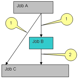
Unusual job definition 3
Assume that job B deletes output condition X. If job B is deleted using the condition inheritance feature, the deletion of output condition X will be lost.
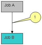
Other feature limitations
-
Parentheses are rearranged
In order to use the condition inheritance feature, Control-M formats must be converted to standard Boolean format, manipulated, and then converted back to Control-M format. In this case, the parentheses are rearranged, although the functionality remains the same. For example:
Control-M format: A (|B |C)
becomes
Control-M format after manipulations: |(A B) |(A C)
-
Adjust condition is ignored
The Adjust Condition feature for a SMART Table is ignored.
-
DO COND is ignored
Output conditions that are associated with a DO COND statement are ignored.
-
Manual conditions
Manual conditions are treated the same way as regular conditions. This may lead to incorrect results.
Displaying Graphic Jobflow
The Graphic Jobflow screen provides a graphic presentation of the job flow dependencies in a given table. It is displayed when option G (Graphic Flow) is specified for a table in the Table List screen.
Use the shifting PFKeys to shift the Graphic Jobflow right (PF11/PF23) and left (PF10/PF22).
The FIND command (PF05/PF17), described in FIND Command, is supported in the Graphic Jobflow screen.
To return to the Table list, press the END key (PF03/PF15).
Two formats for the Graphic Jobflow screen are available, one for color displays and one for non-color displays.
Graphic Jobflow for Color Terminals
Figure 35 Graphic Jobflow for Color Terminals
-------------- GRAPHIC JOBFLOW - TABLE PRODYH ---------------- (2.G)
COMMAND ===>                                         SCROLL===> CRSR

 PRODYJCL  --->  PRODYHTK  ----------------->  PRODYHST
 PRODTHC2  --->  PRODYBCK  --->  PRODYIDK  --->      --->  PRODYBTL
                                     --->  PRODYIZN  --->  PRODYEND

 PROJYFOT  --->  PROJYMRG  --->  PROJYMTI

                          --->  PROJYHO1  --->  PROJYHO2

             --->  PROJYDPY  --->  PROJYDTK  --->  PROYH11   ---

                                         --->  PROJYDLI  --->

PRESS END TO RETURN.  LEFT AND RIGHT TO SEE MORE. COLUMNS: 001 - 080
Size limits for the online display are narrower than the size limits for the printed chart. The online display is limited to 15 levels of dependencies. If the chart cannot be displayed online because it is too large, it can still be printed. For more information, see the description of the CTMRFLW utility in the Control-M chapter of the INCONTROL for z/OS Utilities Guide.
On color terminals, the colors used to display the boxes and arrows can be changed by request. Available colors are sequenced in a loop. Each request changes to the next color in the sequence. Colors can be changed as follows:
Table 48 Color Change Options on Graphic Jobflow Window
|
Option |
Description |
|---|---|
|
Change the color of the boxes |
Press PF04/PF16 |
|
Change the color of arrows |
Type ARROW in the COMMAND field and press Enter. |
Graphic Jobflow for Non-Color Terminals
Figure 36 Graphic Jobflow for Non-Color Terminals
-------------------- GRAPHIC JOBFLOW - TABLE PRODYH ------------------- (2.G)
COMMAND ===>                                                 SCROLL===> CRSR
 .----------.   .----------.                  .----------.
 | PRODYJCL |-->| PRODYHTK |--->-->--->-->--->| PRODYHST |
 `----------'   `----------'                  |          |
 .----------.   .----------.    .--------.    |          |    .----------.
 | PRODTHC2 |-->| PRODYBCK |--->|PRODYIDK|--->|          |--->| PRODYBTL |
 `----------'   `----------'    |        |    `----------'    `----------'
                                |        |    .----------.    .----------.
                                |        |--->| PRODYIZN |--->| PRODYEND |
                                `--------'    `----------'    `----------'
 .----------.   .----------.    .--------.
 | PROJYFOT |-->| PROJYMRG |--->|PROJYMTI|
 `----------'   |          |    `--------'
                |          |    .--------.    .----------.
                |          |--->|PROJYHO1|--->| PROJYHO2 |
                |          |    `--------'    `----------'
                |          |    .---------.   .----------.    .----------.
                |          |--->|PROJYDPY |-->| PROJYDTK |--->| PROYH11  |--
                `----------'    |         |   `----------'    |          |
                                |         |   .----------.    |          |
                                |         |-->| PROJYDLI |--->|          |
                                |         |   `----------'    `----------'

PRESS END TO RETURN.LEFT AND RIGHT TO SEE MORE.COLUMNS:001-08015.38.44
Size limits for the online display are narrower than the size limits for the printed chart. If the chart cannot be displayed online because it is too large, it may still be printed. For more information, see the KeyStroke Language (KSL) User Guide.
Displaying a Job Scheduling Plan
To display the scheduling plan of a job or SMART Table Entity in calendar format, either type P (Plan) by the job or SMART Table Entity name in the Job List screen and press Enter, or enter command PLAN in the Job Scheduling Definition screen. The following window is displayed:
Figure 37 Job Scheduling Plan Window
JOB LIST     LIB: CTM.PROD.SCHEDULE                             TABLE: BACKUP
COMMAND ===>                                                    SCROLL===> CRSR
OPT  NAME ----- DESCRIPTION ---------------------------------------------------
      STARTBKP   START OF DAILY BACKUP
      BACKPL01   DAILY BACKUP OF DATA SETS FROM APPL-L
      BACKPL02   DAILY BACKUP OF SPECIAL FILES FROM APPL-L
      BACKPLW1   WEEKLY BACKUP OF FILES FROM APPL-L #1
      BACKPLW2   WEEKLY BACKUP OF FILES FROM APPL-L #2
      BACKPLW3   WEEKLY BACKUP OF FILES FROM APPL-L #3
      BACKPLW4   WEEKLY BACKUP OF FILES AFTER DAILY FROM APPL-L +
      DASDRPT1   DASD REPORTS AFTER BACKUPS FOR APPL-L
      DASDRPT2   DASD STATISTICS REPORT AFTER BACKUP FOR APPL-L
      ENDPLBKP               +---------------------+
      BACKAC01               |  FROM DATE  050101  |
  P   BACKAC02               |  TO DATE    053101  |
      BACKACW1               +---------------------+
      BACKACW2
      BACKACW3   WEEKLY BACKUP OF FILES FROM APPL-ACCOUNT #3
      BACKACW4   WEEKLY BACKUP OF FILES AFTER DAILY FROM APPL-ACC +
      DASDRPT3   DASD REPORTS AFTER BACKUPS FOR APPL-ACCOUNT
      DASDRPT4   DASD REPORTS AFTER BACKUP FOR APPL-ACCOUNT
      ENDACBKP   END OF BACKUP INDICATION FOR APPL-ACCOUNT
      BACKDD01   DAILY BACKUP OF DATA SETS FROM APPL-DD
OPTIONS S SEL D DEL I INS O ORDER F FORCE J JCL C COPY P PLN T JOBSTAT 15.37.39
The window contains the following fields with default values that can be modified:
Table 49 Job Scheduling Plan Window Fields
|
Field |
Description |
|---|---|
|
FROM DATE |
First date to be included in the job scheduling plan. Default is current working date. |
|
TO DATE |
Last date to be included in the job scheduling plan. Default is one day less than one month after the current working date. |
To display the plan, modify the defaults if desired. Press Enter. The Job Scheduling Plan screen is displayed.
To close the window without displaying the plan, press END (PF03/PF15) or RESET (PF04/PF16).
Job Scheduling Plan Screen
For each month in the requested date range, beginning with the first month in the range, the Job Scheduling Plan screen displays a calendar that indicates the schedule of the job.
The months (within the date range) in which the job (or jobs for a table schedule) is not scheduled are not displayed.
The dates within the date range on which the job is scheduled, according to its basic scheduling criteria, are marked with an asterisk.
Enter NEXT (PF08/PF11/PF20/PF23) or PREV (PF07/PF10/PF19/PF22) in the COMMAND field, or press the appropriate PFKey, to see the next or previous calendar month in the date range.
Press the END key (PF03/PF15) to exit the Job Scheduling Plan screen and return to the Job List screen.
Figure 38 Job Scheduling Plan Screen
JOB NAME: BACKPL02               JOB SCHEDULING         DATES : 010601 - 300601
COMMAND ===>                                                    SCROLL===>
   06   2001        MON   TUE   WED   THU   FRI   SAT   SUN
                                             01    02    03


                     04    05    06    07    08    09    10
                      *     *     *     *     *

                     11    12    13    14    15    16    17
                      *     *     *     *     *

                     18    19    20    21    22    23    24
                      *     *     *     *     *

                     25    26    27    28    29    30
                      *     *     *     *     *


 CMDS: NEXT, PREV, END                                                 19.30.51
The screen indicates the following:
Table 50 Job Scheduling Plan Screen Fields
|
Field |
Description |
|---|---|
|
Job |
Name of the job for which the schedule is requested. |
|
Range |
Requested date range, in mmddyy, ddmmyy, or yymmdd format, depending on the site standard. |
|
Month/Year |
Month and Year currently displayed. |
|
Calendar |
Calendar (day of the week and date) for the currently displayed month. |
|
Schedule |
An asterisk under a date indicates that the job is scheduled on that day. |
Tracking and Control Facility
The Tracking and Control facility provides relevant information about the status of each job and task in the Active environment and enables you to manually intervene in the processing of jobs.
The Active environment contains all the jobs in the Active Jobs file, that is, all jobs that have recently executed, are currently executing, or are scheduled for possible execution in the near future.
The main screen of the Tracking and Control facility is the Active Environment screen, which displays a list of all jobs and their statuses in the Active environment.
The Active Environment screen is accessed by requesting option 3 on the IOA Primary Option menu.
From the Active Environment screen you can request specific actions in relation to a job, or request the display of other screens that provide additional information and capabilities. Possible requests include
-
Change the screen display type to display different information about the jobs in the Active environment.
-
View only jobs belonging to a specific table name.
-
View statistical information about all jobs in the Active environment.
-
Display the reasons why a job has not executed.
-
Place a job in Hold status.
-
Delete a job from the Active environment.
-
Delete a SMART Table Entity and all the jobs in the SMART Table from the Active environment.
-
Undelete a job that has been deleted from the Active environment.
-
Free a held job.
-
Display the log messages of a job.
-
Zoom in on the scheduling details of a job and modify certain parameters.
-
Rerun a job.
-
Confirm the restart and/or rerun of a job.
-
View the list of all runs (job orders) of a particular job, and view the sysout of any or all of those job orders.
-
Display the execution statistics of a job.
-
Display and edit the JCL of a job.
-
Display the list or network of predecessor and successor jobs of a specific job, and display critical path information.
-
Force END OK termination of a job that has not been submitted or that ended NOTOK.
-
Reactivate a job that has "disappeared" or that has failed with status "Reason Unknown".
-
Display the list of archived jobs (in the History file) and restore desired archived jobs to the Active environment.
Active Environment Screen
To enter the Tracking and Control facility, select option 3 on the IOA Primary Option menu. The Active Environment screen is displayed.
Figure 39 Control-M Active Environment Screen
Filter:           ------- CONTROL-M  Active  Environment ------ UP    <D>   (3)
COMMAND ===>                                                    SCROLL ==> CRSR
O Name     Owner    Odate  Jobname  JobID   Typ ------------ Status -----------
  CICSPROD M22      060601 CICSPROD/04368   CST Executing (Run 1)
  CICSTEST M22      060601 CICSTEST/04372   CST Executing (Run 2)
  BRIVPCC  IVP      060601                  TBL Active
  BRCC0001 IVP      060601 BRCC0001/04382   JOB Held Wait Schedule
  BRCC0002 IVP      060601 BRCC0002/04383   JOB Held Ended "OK" (Run3)
                                                Prior Run: Ended "OK"
  BRCCIND  IVP      060601 BRCCIND /04385   JOB Ended "OK"
  BRUPDT02 IVP      060601 BRUPDT02/04387   JOB Ended "OK"
  BRREP002 IVP      060601 BRREP002/04389   JOB Ended "OK"
  BRIVPCCE IVP      060601         /        JOB Wait Schedule
  CRCCEND  IVP      060601         /        JOB Wait Schedule
  INTR0001 M22      060601         /        JOB Ended- Not "OK" Due to CC -
                                                Rerun Needed (Run 3)
                                                Prior Run: Ended- Not "OK" Due
                                                to CC - Rerun was Needed
  INTR0003 M22      060601         /        JOB Wait Schedule
  BRREP003 IVP      060601 BRREP003/04391   JOB Ended "OK"
  BRREP004 IVP      060601 BRREP004/04393   JOB Ended "OK"
  INTR0004 M22      060601 INTR0004/04397   JOB Ended- Not "OK" - Abended
Commands: OPt DIsplay Show HIstory RBal REFresh Auto Jobstat SHPF Note Table
          OPt command toggles between Commands and Options display     15.15.48
It is assumed that you want to see the most recently ordered jobs first. Therefore, by default, the bottom of the Job list is displayed upon entry to the Active Environment screen. This default can be altered by setting Profile variable SACTMOD to T, in which case jobs are displayed from the top of the Job list. Profile variable SACTMOD is described in the INCONTROL for z/OS Administrator Guide.
AutoRefresh mode is available in this screen.
To exit the Active Environment screen, press the END key (PF03/PF15).
For color terminals, jobs with different statuses are displayed in different colors. Each of the colors in the following table has been defined as the default for one of these statuses. These statuses are described more fully in Table 64 in Fields of the Show Screen Filter Window.
To change color definitions, see your INCONTROL administrator.
Table 51 Default Colors for Active Missions Screen
|
Color |
Corresponding Status |
|---|---|
|
Blue and White |
Jobs waiting to be scheduled |
|
Yellow |
Jobs that are executing or about to execute |
|
Red |
Jobs that are in error or ended NOTOK or LATE (submitted and/or executing jobs) |
|
Green |
Jobs that ended OK or were forced OK |
|
Pink |
Jobs that require special user action (such as Wait Confirmation) |
Display Types of the Active Environment Screen
The information in the Active Environment screen can be displayed in different formats or display types. A number of predefined display types are available.
While in the Active Environment screen, the display type can be changed by the DISPLAY command. The DISPLAY command is described in Commands of the Active Environment Screen.
Table 52 Predefined Display Types
|
Type |
Description |
|---|---|
|
D |
Default display type. |
|
A |
All info display type. |
|
N |
Network display type. |
|
F |
Flow rerun display type. |
|
P |
Table display type (same as display type D). |
The INCONTROL administrator can use display type support to tailor the display layout by adding lines, fields, changing colors, and so on. Additional information about display type support is provided in the section on customizing IOA display format members in the INCONTROL for z/OS Administrator Guide.
The $$ACTDOC member in the IOA MSG library contains information that is useful for customizing the Control-M Active Environment screen and creating and modifying display types for screens 3, 3.N, 3.G and the History Environment screen.
Upon reentering the screen, the last-used display type is displayed.
The Default and All Info predefined display types, and the fields they contain, are discussed in Format of the Active Environment Screen.
The Network display type, although available in this screen, is generally useful only in the Job Dependency Network screen, and is described in Job Dependency Network Screen.
Primary and Alternate Bottom Lines
The last two lines of the Active Environment screen are used to display the list of available commands and options.
Because there are too many commands and options to list at once, the list is divided into two parts, each part consisting of two lines, as follows:
-
Upon entry to the screen, the set of available commands is displayed. Because this list is displayed upon entry to the screen, it is referred to as the Primary Bottom line.
CopyCommands: OPt DIsplay Show HIstory RBal REFresh Auto Jobstat SHPF Note Table
OPt command toggles between Commands and Options display 15.15.48 -
Upon request (using command OPT), the set of available options is displayed (in place of the set of commands). The list of available options is referred to as the Alternate Bottom line.
CopyOpt: ? Why L Log H Hold Z Zoom R Rerun A Activate O Force OK V View Sysout
N Net D Del F Free S Stat T Table U Undelete J JCL Edit C Confirm 15.46.06
To toggle back and forth between the two sets of bottom lines, type OPT in the COMMAND field and press Enter.
Available commands are described in Commands of the Active Environment Screen. Available options are described in Options of the Active Environment Screen.
Format of the Active Environment Screen
Display Type D (Default)
Below is an example of the Default display type. It contains the most relevant information about the job.
Figure 40 Display Type D (Default)
Filter: DEFAULT ------- CONTROL-M Active Environment ------ UP <D> (3)
COMMAND ===> SCROLL ==> CRSR
O Name Owner Odate Jobname JobID Typ ----------- Status ------------
CICSPROD M22 060601 CICSPROD/04368 CST Executing (Run 1)
CICSTEST M22 060601 CICSTEST/04372 CST Executing (Run 2)
BRIVPCC IVP 060601 TBL Active
BRCC0001 IVP 060601 BRCC0001/04382 JOB Held Wait Schedule
BRCC0002 IVP 060601 BRCC0002/04383 JOB Held Ended "OK" (Run3)
Prior Run: Ended "OK"
BRCCIND IVP 060601 BRCCIND /04385 JOB Ended "OK"
BRUPDT02 IVP 060601 BRUPDT02/04387 JOB Ended "OK"
BRREP002 IVP 060601 BRREP002/04389 JOB Ended "OK"
BRIVPCCE IVP 060601 / JOB Wait Schedule
CRCCEND IVP 060601 / JOB Wait Schedule
INTR0001 M22 060601 / JOB Ended- Not "OK" Due to CC -
Rerun Needed (Run 3)
Prior Run: Ended- Not "OK" Due
to CC - Rerun was Needed
INTR0003 M22 060601 / JOB Wait Schedule
BRREP003 IVP 060601 BRREP003/04391 JOB Ended "OK"
BRREP004 IVP 060601 BRREP004/04393 JOB Ended "OK"
INTR0004 M22 060601 INTR0004/04397 JOB Ended- Not "OK" - Abended
Commands: OPt DIsplay Show HIstory RBal REFresh Auto Jobstat SHPF Note Table
OPt command toggles between Commands and Options display 15.15.48Fields of Display Type D (Default)
Table 53 Fields in the Default Display Type
|
Field |
Description |
|---|---|
|
Filter |
Name of the currently active screen filter. For more information, see Filtering the Active Environment Screen Display. |
|
Control-M Status |
Indicator of whether Control-M monitor is UP, DOWN or SUSP (suspended). |
|
Display Type |
Indicator of the currently used display type, such as D for the Default display type. |
The following is displayed for each job:
Table 54 Fields for Each Job Default
|
Field |
Description |
|---|---|
|
O(ption) |
Field for requesting options to be activated on jobs. |
|
Name |
Name of the member containing the JCL of the job, or name of the started task. |
|
Owner |
ID of the owner of the job. |
|
Odate |
Original scheduling date of the job. For more information, see Date Definition Concepts. |
|
Jobname |
Job name – generally available only after job submission. |
|
JobID |
Job number – generally available only after job submission. |
|
Typ |
Task type or Table type. |
|
Status |
Job (task) status, For more information, see Job Statuses. |
The information in the following table can be displayed by request, along with the STATUS information. For more information, see Commands of the Active Environment Screen.
Table 55 Other Information in the STATUS Field
|
Type |
Descriptions |
|---|---|
|
TABLE |
Table name of the job, discussed in Job Production Parameters. |
|
CPU |
ID of the CPU on which the job is executing or has executed. The CPU ID is displayed only for those jobs subjected to dynamic resource acquisition (that is, jobs for which Control-M dynamically decided to which CPU they would be submitted). Dynamically acquired resources are identified by a $ character in the Quantitative resource name. For more information, see "CPUID" in Commands of the Active Environment Screen. |
|
OrderID |
Order ID of the job. For more information, see "ORDERID" in Commands of the Active Environment Screen. |
|
Desc |
Job description. For more information, see "DESC" in Commands of the Active Environment Screen. |
|
Table |
Scheduling library and table of the job. For more information, see "TABLE" in Commands of the Active Environment Screen. |
|
Note |
First line of the note (if one exists). For more information, see "NOTE" in Commands of the Active Environment Screen. |
O Name     Owner    Odate  Jobname  JobID   Typ ------- Status -----------
 TO5SP115 TO5      060601         /        JOB Wait Schedule Table=NRD-TBL
 CPU=A OrderID=0003E ===>BACKUP
 SCHED-LIB=CTM.PROD.BKP(SPBKP)
 *** Note ***
Display Type A (All Info)
The following is an example of the All Info display type. In addition to the Default information, it contains statistical information about the job run.
Figure 41 Display Type A (All Fields)
Filter:           ------- CONTROL-M  Active  Environment ------ DOWN  <A> - (3)
COMMAND ===>                                                    SCROLL ==> CRSR
O Name     Owner    Odate  Jobname  JobID   Typ ----------- Status ------------
  DAILYPRD PRODMNGR 060601                  JOB Wait Schedule
   OrderID 001Q6  TBL CTM-CONTROL
   MaxRC                          Res. Use: Y
   Time Fr:       Time Un:       Priority: 00
    Due-In: 0859  Due-Out: 0859  Late:
   Avg Elaps: 0000               RBA:  000002
  DAILYSYS SYSTEM   060601                  JOB Wait Schedule
   OrderID 001Q7  TBL CTM-CONTROL
   MaxRC                          Res. Use: Y
   Time Fr:       Time Un:       Priority: 00
    Due-In: 0859  Due-Out: 0859  Late:
   Avg Elaps: 0000               RBA:  000003
  CTMLDNRS PRODMNGR 060601                  JOB Wait Schedule
   OrderID 001Q8  TBL CTM-CONTROL
   MaxRC                          Res. Use: Y
   Time Fr:       Time Un:       Priority: 00
    Due-In: 0859  Due-Out: 0859  Late:
   Avg Elaps: 0000               RBA:  000004
  CTMCLRES PRODMNGR 060601                  JOB Wait Schedule
Opt: ? Why L Log H Hold Z Zoom R Rerun A Activate O Force OK V View Sysout
     N Net D Del F Free S Stat T Table U Undelete J JCL Edit C Confirm 14.50.56
Fields of the Display Type A (All Info)
Below is a description of fields in the All Info display type that do not appear in the Default display type. The fields that appear in the Default display type are described in the preceding section.
Table 56 Fields in the All Fields Display Type
|
Field |
Description |
|---|---|
|
TBL |
Name of the table. |
|
MaxRC |
Highest return code returned for the job. |
|
Res. Use |
Indicates (yes or no) whether the job uses (Control and/or Quantitative) resources. |
|
Time Fr |
Time the job began execution. |
|
Time Un |
Time the job ended execution. |
|
Priority |
Priority at which the job executed. |
|
Due-In |
Time by which the job was to be submitted. |
|
Due-Out |
Time by which the job execution must complete. |
|
Late |
Indicates if the job is late. Valid (Late) values:
|
|
Avg Elaps |
Average elapsed run time of the job. |
|
RBA |
Relative Byte address of the job in the Active Jobs file. |
Commands of the Active Environment Screen
The commands in the following table can be requested by typing the command in the COMMAND field of the Active Environment screen and pressing Enter.
Table 57 Commands of the Active Environment Screen
|
Command |
Description |
|---|---|
|
OPT |
Toggles between the Primary Bottom line (composed of most of the available Primary commands) and the Alternate Bottom line (composed of all available options). |
|
DISPLAY |
Used to change display types. The format of the command is DISPLAY x (abbreviated DI x) where x is the desired display type. For example, DI A displays the All Info display type. For a list of display types, enter DISPLAY ? to show the Display Options window. To select a display type in the window, type S in the Option field next to the ID. To exit the window without selecting a display type, press the END key (PF03/PF15). DI N displays the Net fields display. Valid predefined displays are:
|
|
SHOW |
Activates the specified screen filter, or opens the Show Screen Filter window or the Display Filters window, depending on the format of the command. For more information, see Filtering the Active Environment Screen Display. Valid formats are:
|
|
HISTORY |
Displays the jobs in the History Jobs file in the History Environment screen, which is described in History Environment Screen. |
|
RBAL |
Scrolls the Active Environment screen so that the job with the specified relative byte address (RBA) is displayed at the top of the screen. The format of the command is RBAL rba (abbreviated RB rba) where rba is the relative byte address of the job. This command is especially useful for determining which job is using a particular resource. The RBA of the job using a resource is indicated in the IOA Conditions/Resources screen (Screen 4). |
|
REFRESH |
Activates processes in the Control-M monitor for the recalculation of job dependency information. To choose the type of recalculation to perform, specify one of the following parameters along with the REFRESH command:
Although available in the Active Environment screen, this command is generally used in the Job Dependency Network screen. |
|
AUTO |
Activates AutoRefresh mode. The format of the command is AUTO n where n is any number of seconds within the range 1 through 99. For more information, see AutoRefresh Mode. |
|
JOBSTAT |
Displays the Statistics screen, which provides statistics for the specified job. For more information, see Statistics Screen. Unlike Option S (STAT), which can be entered only for jobs appearing in the Active Environment screen, the JOBSTAT command can be entered for any job. Format of the command is JOBSTAT jobname tablename Specification of a Table name is optional, but if no Table name is specified, statistics are displayed only for jobs not belonging to any Table. |
|
SHPF |
Displays the PFKey assignment of the screen. For more information, see Commands and PFKeys. |
|
NOTE |
Displays or hides the first line of a note (if one exists). The format of the command is NOTE {ON|OFF} where
If no ON of OFF qualifier is entered, the NOTE command toggles between displaying and hiding the first line of the note. The current setting is kept in the user profile for the next time the screen is displayed. |
|
TABLE |
Displays or hides the name of the job scheduling library and table from which the job was ordered. The format of the command is TABLE {ON|OFF} where
If no ON of OFF qualifier is entered, the TABLE command toggles between displaying and hiding the name of the job scheduling library and table. The current setting is kept in the user profile for the next time the screen is displayed. |
|
CPUID |
Displays or hides the CPU ID of jobs subjected to dynamic resource acquisition. When displayed, the CPU ID on which the job is running (or executed on) appears after the job status. The format of the command is: CPUID {ON|OFF} where:
If no ON or OFF qualifier is entered, the CPUID command toggles between displaying and hiding the CPU ID. The current setting is kept in the user profile for the next time the screen is displayed. |
|
DESC |
Displays or hides the description of each job. The format of the command is: DESC {ON|OFF} where
If no ON or OFF qualifier is entered, the DESC command toggles between displaying and hiding the description. The current setting is kept in the user profile for the next time the screen is displayed. |
|
DUMP |
Used in special circumstances when requested by BMC Customer Support. The command is used to capture abends resulting from either internal or external events. The format of the command is: DUMP {ON|OFF} where
If no ON of OFF qualifier is entered, the DUMP command toggles between providing and not providing a DUMP. The current setting is kept in the user profile for the next time the screen is displayed. When DUMP ON is requested, the DUMP ON indicator is displayed in the first line of the screen. |
|
TABLE (PF11/PF23) |
Displays or hides the table name. When displayed, the name of the table appears after the job status. The format of the command is: TABLE {ON|OFF} where:
If no ON or OFF qualifier is entered, the TABLE command toggles between displaying and hiding the table name. The current setting is kept in the user profile for the next time the screen is displayed. |
|
OIDL |
Scrolls the Active Environment screen so that the job with the specified order-ID is displayed at the top of the screen. The format of the command is: OIDL ord_ID where ord_ID is the order-ID of the job. |
|
ORDERID |
Displays or hides the order ID of each job. The format of the command is: ORDERID {ON|OFF} where:
If no ON of OFF qualifier is entered, the ORDERID command toggles between displaying and hiding the order ID. The current setting is kept in the user profile for the next time the screen is displayed. |
|
VIEW (PF04/PF16) |
Displays the Global View screen, which provides a statistical overview of the status of jobs running under Control-M. For more information, see Global View Screen. |
|
VIEW GRAPH (VG) |
Displays the View Graph screen, which provides a graphic statistical overview of the status of jobs running under Control-M. For more information, see View Graph Screen. |
Options of the Active Environment Screen
Select an option by typing it in the O (Option) field to the left of the job order and pressing Enter. The following table describes the available options:
Table 58 Options of the Active Environment Screen
|
Option |
Description |
|---|---|
|
? (Why) |
Display the Why screen, which shows the reasons the job is in Wait Schedule status. For more information, see Why Screen. |
|
L (Log) |
Display the Log screen, which shows all IOA Log messages for the specified job. For more information, see IOA Log Screen. |
|
H (Hold) |
Hold Control-M operations on the job order. Only Control-M operations concerning the job order are halted. The flow of the job through the operating system is not held. The HOLD request is recorded in the IOA Log file. The status of the job is changed to REQUESTED HELD. If the Control-M monitor is active, the status changes to HELD. In some cases, a HOLD request may be rejected by the monitor. |
|
Z (Zoom) |
Display the Zoom screen, which "zooms in" on job details. For more information, see Zoom Screen. |
|
R (Rerun) |
Rerun the job. A Rerun window is displayed. For more information, see Confirm Rerun Window. |
|
A (Activate) |
Reactivate a job or started task that has a status of either DISAPPEARED or FAILED REASON UNKNOWN. Control-M searches the MVS/JES queues for the disappeared or failed job or started task. A job or started task is assigned a DISAPPEARED status if it has been accidentally deleted. Also, if JES is very busy, it sometimes sets the status of a job or started task to DISAPPEARED even though the job or started task actually exists. A job or started task is assigned a status of FAILED REASON UNKNOWN whenever Control-M encounters a problem reading the SYSDATA files of the job and therefore cannot check the completion status of the job. |
|
O (Force OK) |
Force the job to complete with ENDED OK status. For more information, see Force OK Confirmation Window. |
|
§Restart§ V (View Sysout) |
View the execution history of the job in the Job Order Execution History screen. From this screen, the Sysout Viewing screen, which displays the archived SYSDATA of the job, can be requested. For more information on these screens, see §Restart§ Job Order Execution History Screen, and §Restart§ Sysout Viewing Screen. |
|
N (Net) |
Display the Job Dependency Network screen, which shows all the predecessor and successor jobs for the selected job. For more information, see Job Dependency Network Screen. |
|
D (Del) |
Delete the job. For more information, see Deleting a Job and Delete Confirmation Window. If you delete a SMART Table Entity, all jobs which are part of that SMART Table are also deleted. |
|
F (Free) |
Free a held job order. All Control-M operations for the job order are resumed. If the job is currently in the job queue of the operating system in HOLD state, the job is not released. The FREE request is recorded in the IOA Log file. The status of the job is changed to REQUESTED FREE. If the monitor is active, the FREE request is accepted after a few seconds. |
|
S (Stat) |
Display the Statistics screen, which shows job run statistics. Statistics for a job that is not in the Active environment can be displayed using command JOBSTAT. For more information, see Statistics Screen. |
|
T(TBL) |
Display the SMART Table Entity (TBL entry) and all jobs that are part of that SMART Table. This option can be entered next to a TBL entry, or next to any job that is part of a SMART Table. Jobs that are part of a SMART Table are marked with the letter T (TBL) to the right of the SMART Table name under display type A (Activate). |
|
U (Undelete) |
Cancel a previously requested Delete. Valid only for jobs deleted by request. The job is returned to its status prior to the delete request. If you undelete a job that is part of a deleted SMART Table, the SMART Table Entity is undeleted, together with the individual job. However, if you undelete a deleted SMART Table, only the SMART Table is undeleted, and not the jobs in the SMART Table. If you want also to undelete a job or jobs that are part of that SMART Table, you must undelete each job individually. |
|
J (JCL Edit) |
Edit the member that contains the JCL of the job. By default, if the specified JCL member exists in the OVERLIB library, that member is edited. If the JCL member does not exist in the OVERLIB library, the member is edited in the MEMLIB library. |
|
C (Confirm) |
Confirm that this job is to be scheduled. A window is displayed to permit user confirmation. Entering Y sets the status of the job to WAIT SCHEDULE. For more information, see Confirm Scheduling Window. |
|
% (Simulation) |
Simulates the action of the Control-M Submission mechanism for a job that was previously placed in the Active Jobs file. This option is similar to the CTMAESIM utility, which is described in Testing AutoEdit Syntax. The option produces the JCL stream for the job and a report of the process. The IOA Editor directs the output of the AutoEdit simulation to the user’s screen, with the following header line displayed: CONTROL-M_AUTOEDIT_SIMULATION(memname) where memname is the name of the JCL member of the job. The report consists of two parts:
The user can use the IOA editor to edit the output, and save it as a member in a library.
|
|
B (Bypass)
|
Display the BYPASS option window. This option enables you to specify criteria and resources to be ignored for those jobs that have a status of WAIT SCHEDULE. By default, all fields in the BYPASS option window are set to N. You may set any or all these fields to Y, with the following effects: IN Criteria:
Additional Options:
|
|
W |
Display the MVBO/Job Optimizer screen for the selected job. Valid only for jobs under the control of MAINVIEW Batch Optimizer (MVBO). The MVBO/Job Optimizer screen is described in the MAINVIEW Batch Optimizer/Job Optimizer Reference Manual. |
|
K (Kill) |
(Only jobs that have Executing status) "Kills" the job, meaning that the job is cancelled (causing the job to fail with a system abend code of S222), and the status of the job is changed to ENDED NOTOK. Kill may not be specified for Started tasks or NJE jobs. |
|
X (Exit) |
Invoke user exit CTMX008. Placing an X next to a job in screen 3 keeps the details of the current job as input parameters for the exit. For information about the function of user exit CTMX008, please consult with your site’s IOA administrator. |
Job Statuses
The following job statuses can appear in the Active Environment screen:
Table 59 Job Statuses for the Active Environment Screen
|
Status |
Description |
|---|---|
|
ACTIVE |
The job is a dummy job that has not yet reached the post-processing phase. |
|
BUT NOT FOUND n TIMES |
If a job is not found at least once, this status displays the number of times (n) Control-M has looked for the job. If the job is still not found after 10 times, the status is changed to DISAPPEARED. JOB SUBMITTED BUT NOT FOUND 5 TIMES The job was submitted, but may have been purged. After checking 10 times, Control-M changes the status to DISAPPEARED. This default number can be changed by your INCONTROL administrator. |
|
§Restart§ CLEANUP |
Job is being run for Cleanup. |
|
DELETED |
The job order was deleted by an authorized user. |
|
DISAPPEARED |
Job disappeared completely. This status only occurs after a NOT FOUND status. |
|
ENDED NOT "OK" |
Job ended NOT OK. |
|
ENDED NOT "OK" – ABENDED |
Job abended. |
|
ENDED NOT "OK" – DUE TO CC |
Condition code that is not defined as OK has occurred. |
|
ENDED NOT "OK" – FAILED – REASON UNKNOWN |
This usually occurs following a system crash. |
|
ENDED NOT "OK" – JCL ERROR |
Job failed due to JCL error. |
|
ENDED NOT "OK" – RERUN NEEDED |
Rerun is needed for the job. |
|
ENDED NOT "OK" – RERUN WAS NEEDED |
Rerun was required for the previous execution of the job. |
|
ENDED NOT "OK" – TERM ON NCT2 |
The job was terminated by Control-M due to a NOT CATLGD 2 error. |
|
ENDED "OK" |
Job finished executing OK. |
|
ENDED "OK" FORCED OK |
Job ended OK due to a Force OK request. |
|
EXECUTING |
Job is executing. |
|
EXECUTING (SYSOUT IN HOLD STATUS) |
Job was placed in HOLD status by an operator issued JES HOLD command before Control-M could read the job’s output. |
|
GOING TO START |
Started task is eligible to be run and is about to be activated. |
|
(TBL HELD) |
The SMART Table Entity of which the job is part is in Held status, and as a result, the job itself is being logically held. (While the job’s SMART Table Entity is being held, actions that require a Held status, such as Delete, Zoom, and Save, can be performed against the job. In addition, the Control-M monitor does not handle the job. For example, if the job is in WAIT SCHEDULE status it is not selected for submission.) |
|
HELD |
Job is in hold status. |
|
LATE |
Job did not finish executing by the time specified in a SHOUT WHEN LATE statement. |
|
LATE EXECUTION |
The elapsed runtime of the job is outside the acceptable limits defined in a SHOUT WITHIN EXECTIME statement. |
|
LATE SUBMISSION |
Job was not submitted by the time specified in a SHOUT WHEN LATESUB statement. |
|
NJE JOB |
The job is not currently found in either Remote or Host node, but is in the process of transmission between nodes. (Either the job is being transmitted to the Remote node for execution, or the sysdata output of the job is being transmitted to the Host node.) Control-M continues to search for the job until it is located on one of the nodes. BMC recommends that you do not purge jobs on the Remote node. However, if you do purge a job on the Remote node, you must notify Control-M of the event by changing the value in the NJE field in the Active Environment Zoom screen (Screen 3.Z) to ' ' (Blank). After a short time, the job status changes to Disappeared. |
|
NJE JOB (ID CHANGED) |
The job ID of the NJE job has changed. When the job’s sysdata output was transmitted back to the Host NJE node, the Control-M monitor detected that the original job ID of the NJE job is occupied by another job. The Control-M monitor continues to search for a job to match the new job ID. |
|
NOT FOUND |
Job not found in the queue. Check that the job or its sysout has not been accidentally deleted. This status may also appear when JES is very busy. In such a case, Control-M waits for JES until it confirms that the job is lost. |
|
NOT STARTED |
Starting of the started task failed. |
|
NOT SUBMITTED |
Submission of the job failed. |
|
NOTE |
A Note has been added to the job, through the Zoom screen. |
|
ON HST FILE |
Job is currently in the History file. If the job is included in the flow of jobs being rerun, it will be restored to the Active Jobs file before being rerun. This option appears only in the Rerun Flow Job List window. |
|
ON OUTPUT QUEUE |
Job is on the output queue of the remote NJE node or on the output queue of the host node with a changed job ID. |
|
PRIOR RUN |
Termination status of the previous job (or cyclic task) execution (for jobs that have been rerun). |
|
PROBLEMS READING SYSOUT |
Usually means that problems prevent the Control-M monitor from reading the job’s output. |
|
PSEUDO |
At the time when the job was ordered, Control-M automatically converted it to a DUMMY job. |
|
RELEASED |
On Spool job has been released and is waiting to be executed. |
|
REQUESTED CHANGE |
Job parameters were changed using the Zoom option, but the request has not yet been performed by the Control-M monitor. |
|
REQUESTED FORCE OK |
A Force OK request was issued for a held job, but the request has not yet been performed by the Control-M monitor. |
|
REQUESTED FREE |
A free request was issued for a held job, but the request has not yet been performed by the Control-M monitor. |
|
REQUESTED HELD |
A hold request was issued for the job, but the request has not yet been performed by the Control-M monitor. |
|
REQUESTED REACT |
An activate request was issued for a job, but the request has not yet been performed by the Control-M monitor. |
|
REQUESTED RERUN |
A rerun request was issued for the job, but the request has not yet been performed by the Control-M monitor. |
|
§Restart§ RESTARTED) |
Job has run (executed) with the restart step under Control-M/Restart (that is, a restart has been performed). |
|
RESTORED |
This job was restored from the History file. If this status is displayed in the History Environment screen, the job has been restored, rerun, and then copied to the History file as part of the New Day or a User Daily procedure. |
|
RUN n |
Run number. Incremented each time a cyclic task is executed or a job is rerun. |
|
STARTED |
Started task started, but is not yet in the operating system’s job queue. |
|
SUBMITTED |
Job submitted, but is not yet in the operating system’s job queue. |
|
WAIT CONFIRMATION (FOR SCHEDULE) |
Job is waiting for manual confirmation before it can be scheduled. |
|
§Restart§ WAIT CONFIRMATION (WITH RESTART) |
Job is waiting for manual restart confirmation. |
|
WAIT EXECUTION |
Job is in the operating system’s job queue waiting to be executed. |
|
WAIT RELEASE |
On Spool job is eligible to be run and is about to be released. |
|
WAIT SCHEDULE |
Job is waiting to be scheduled. |
|
WAIT SCHEDULE ON SPOOL |
Job is waiting to be scheduled but is already in input queue on spool. |
|
WAIT SCHEDULE (PIPE) |
For MAINVIEW Batch Optimizer (MVBO) users. Job is waiting to be scheduled and is a participant in a Pipe (Collection). |
|
WAIT SUBMISSION |
Job is eligible to be run and is about to be submitted. |
|
§Restart§ (WITH RESTART) |
The restart step under Control-M/Restart will be added to the JCL of the job when the job is submitted (that is, a restart will be performed). |
SMART Table Entity Statuses
The following statuses can appear for the SMART Table Entity in the Active Environment screen:
Table 60 SMART Table Entity Statuses for the Active Environment Screen
|
Status |
Description |
|---|---|
|
ACTIVE |
All runtime criteria for the SMART Table Entity have been satisfied, but at least one job in the SMART Table has not ended and no job in the SMART Table has ended NOTOK. |
|
ACTIVE - IN ERROR |
All runtime criteria for the SMART Table Entity have been satisfied, but at least one job in the SMART Table has not ended and one or more jobs in the SMART Table ended NOTOK. |
|
ENDED NOTOK |
All jobs in the SMART Table have ended. At least one job ended NOTOK. |
|
ENDED OK |
All jobs in the SMART Table ended OK. |
|
(ORDERING) |
A SMART Table Entity has been ordered to the Active Jobs file, but not all of its jobs have been placed in the Active Jobs file, or connected to the SMART Table Entity. The ORDERING status disappears when all jobs in the SMART Table appear in the Active Jobs file and are connected to the SMART Table Entity. Status ORDERING is an add-on to the SMART Table Entity’s regular status. |
|
REQUESTED DELETE |
A delete request was issued for the SMART Table Entity, but the request has not yet been performed. |
Filtering the Active Environment Screen Display
Screen filters may be used to filter the Active Environment screen display.
A filter consists of a set of record selection criteria (selection fields and their values). Only records that conform to selection criteria specified in the filter are displayed on the screen.
The INCONTROL administrator may predefine filters and place them in the General profile.
Each user can activate an existing filter in the Active Environment screen by typing the command SHOW in the COMMAND line of the Active Environment screen.
The filtering feature utilizes two different windows, the Show Screen Filter window and the Display Filters window:
-
Each user can define and name multiple filters for the screen by using the Show Screen Filter window, which is described in Editing Filter Criteria. User-defined filters are stored in the user profile. Filters that are kept in the user profile can be activated only by the user who defined the filter.
-
Users can display the list of all available filters by opening the Display Filters window.
A predefined default filter (DEFAULT) is supplied for the Active Environment screen. Site-defined defaults determine whether the last filter used or the DEFAULT filter is activated upon reentry to the Active Environment screen.
Activating a Known Filter in the Active Environment screen
The SHOW command may be used to activate an existing filter when you know the filter name. To activate an existing filter in the Active Environment screen, type the command SHOW in the COMMAND field, as follows:
SHOW namewhere name is the name of the filter to be activated.
Displaying the List of Available Filters
If you do not know the name of a filter, you can display the list of available filters in the Display Filters window. The display includes Global filters that are available to all users, and user-defined filters that are only available to the individual user.
You can then select a filter from the Display Filters window for activation or editing.
To open the Display Filters window, type the command SHOW ? in the COMMAND field. The Display Filters window is opened.
Filters that are included with Control-M are those appearing in the Display Filters window. These system-provided filters do not display descriptions.
Figure 42 Display Filters Window
Filter: DEFAULT   ------- CONTROL-M  Active  Environment ------ DOWN  <D> - (3)
COMMAND ===>                                                    SCROLL ==> CRSR
O Name     Owner    Odate  Jobname  JobID   Typ ----------- Status ------------
  CICSPR   M96      270601                  JOB Held Wait Schedule (Pipe)
  CICSPR   M96      270601                  JOB Held Wait Schedule (Pipe)
  BRIVPC   M96      270601                  JOB Held Wait Schedule (Pipe)
  KA +-----------------------------------+  JOB Held Wait Schedule (Pipe)
  KA |          DISPLAY FILTERS          |  JOB Held Wait Schedule (Pipe)
  DE | CMD ==>           SCROLL==> CRSR  |  TBL Held Active
  NO |  O NAME     DESCRIPTION           |  JOB Held Ended "OK" Forced OK
  DA |    CONFIRM  WAIT CONFIRM. JOBS    |  JOB Held Ended-"OK"
  DE |    DEL      ONLY DELETED JOBS     |  TBL Active
  IO |    END      ALL ENDED JOBS        |  JOB Held Ended "OK"
  IE |    ENDNOTOK ENDED NOT-OK JOBS     |  JOB Held Wait Schedule
  DA |    ENDOK    ENDED OK JOBS         |  JOB Wait Schedule
  DA |    EXEC     EXECUTING JOBS        |  JOB Wait Schedule
  CT |    LATE     LATE JOBS             |  JOB Wait Schedule
  CT |    WAIT     JOBS ON WAIT QUEUE    |  JOB Wait Schedule
  IE |    ECSALL   ALL JOBS IN AJF       |  JOB Ended "OK"
  NO | =========>>> BOTTOM <<<========== |  JOB Wait Schedule
  NO |                                   |  JOB Wait Schedule
  NO |  OPTIONS  S  SELECT  E  EDIT      |  JOB Wait Schedule
Comm +-----------------------------------+ resh Auto Jobstat SHPF Note Table
          OPt command toggles between Commands and Options display     15.21.28
The Display Filters window displays the following information:
Table 61 Field of the Display Filters Window
|
Field |
Description |
|---|---|
|
NAME |
Name of the filter as it appears in the General or user profile. |
|
DESCRIPTION |
Description of the filter. |
When you create a user-defined filter and provide a description for that filter, the filter, and its description, are both displayed in the Display Filters window.
To select a filter in the list for activation or editing, type the appropriate option in the O (Option) field to the left of the filter name, and press Enter.
Table 62 Options of the Display Filters Window
|
Option |
Description |
|---|---|
|
S (SELECT) |
Activate the filter. The display of jobs in the Active Environment screen is filtered according to the filter criteria. |
|
E (EDIT) |
Display the filter's filtering criteria in the Show Screen Filter window to enable editing of the filter. |
Editing Filter Criteria
The Show Screen Filter window enables you to create or modify a filter.
-
To open an existing filter for editing, either:
-
Type SHOW name EDIT in the Active Environment screen, where name is the name of the filter.
-
Type E (Edit) next to the filter name in the Display Filters window and press Enter.
-
-
To edit the currently active filter, it is unnecessary to type the name or Edit. Just type SHOW in the COMMAND field and press Enter, or press PF02/PF14.
-
To create a new filter, open any existing filter and enter a new name and description in the FILTER and DESC fields, which are described in Table 63 in Fields of the Show Screen Filter Window.
The Show Screen Filter window is displayed:
Figure 43 Show Screen Filter Window
--------------------------- Show Screen Filter -----------------------(3.SHOW)-
 Filter            Save   (Y/N) Desc:
 Memname
 Table
 Sch Lib                                              Tbl
 ======== In Process Y ======= | Ended          Y | ======= State Y ========
 ---------------------------------------------------------------------------
 Wait Sched   Y  Wait time   Y | Ended "OK"     Y | Free      Y  Forced OK Y
 Wait Conf    Y  Wait Cond   Y | Not "OK"       Y | Held      Y  Tbl Held  Y
 Wait SUB     Y  Wait quant  Y | Rerun          Y | On Req    Y  CMEM Forc Y
 Submitted    Y  Wait contrl Y | Disappeared    Y | Deleted   N  Note      Y
 Wait Exec    Y  Tbl Active  Y | Abended        Y | Late      N  Restarted Y
 Executing    Y                | Unexpected CC  Y | Pseudo    N
 On Out Queue Y                | JCL Error      Y |
 Task Type: Job Cyc Emr Stc Cst Est Ecj Ecs Wrn Tbl Tbc
             Y   Y   Y   Y   Y   Y   Y   Y   Y   Y   Y
 Res Name
 Resource Type: In Y Out Y Conds Y Resource Y Control Y
 Owner
 Odate:  From              To               Priority
 Job                       Appl
 CPU Id           LPAR                           RBC
 Workload                                            Dummy Y
-----------------------------------------------------------------------------
Fields of the Show Screen Filter Window
The Show Screen Filter window contains the following fields:
Table 63 Fields of the Show Screen Filter Window
|
Field |
Description |
|---|---|
|
Filter |
User-assigned name of the filter. The name entered in the Filter field may be modified. If there are unsaved changes to a filter in memory (discussed in Closing the Show Screen Filter Window), an asterisk appears to the right of the filter name. |
|
Save (Y/N) |
Specifies whether to save modifications to the filter upon closing the window. |
|
Desc: |
User-defined description of the filter. The description entered here appears next to the name in the Display Filters window. |
The fields listed in Table 64 define the selection criteria to be applied to the screen. Fill in these selection criteria as desired.
The selection criteria shown in Table 64 marked with the symbol P support masking. For more information, see Character Masking.
For compatibility with versions prior to version 6.2.xx, the SACTMSK profile variable can be used to specify how to treat character search criteria that do not use masking characters. The default setting (Y) results in Control-M treating all character search criteria as if a masking character was entered. For example, if AB was entered as a member name to be searched, by default this entry is treated as AB*.
Table 64 Show Screen Filter Window Selection Criteria
|
Criterion |
Description |
|
|---|---|---|
|
MemnameP |
Show only jobs of the specified member name. A maximum of five member names may be specified. |
|
|
TableP |
Show only jobs of the specified table. A maximum of two tables may be specified. |
|
|
TblP |
Show only specified tables in the scheduling library. The scheduling library table name refers to the SCHDTAB field in the 3.Z screen. A maximum of two tables may be specified. For each table created in version 7.0 and later, the scheduling library table name is the same as the SMART Table name. However, in earlier versions, the scheduling library table name can be different than the SMART Table name, see General Information for MEMNAME. |
|
|
status
|
Select only jobs that conform to the status selection criteria. Statuses are divided into three groups under the following headings: In Process, Ended, and State. The following logic applies to these headings:
The following logic applies to the fields under these headings:
|
|
|
In Process – This heading is for the status of jobs that are not yet finished. |
||
|
Wait Sched |
Jobs waiting to be scheduled |
|
|
Wait Conf |
Jobs waiting for confirmation |
|
|
Wait Sub |
Jobs waiting to be submitted |
|
|
Submitted |
Jobs submitted but not yet in queue |
|
|
Wait Exec |
Jobs waiting to be executed |
|
|
Executing |
Jobs that are currently executing |
|
|
On Out Queue |
Jobs on the output queue that have not yet been processed by Control-M, for example, because of a system crash |
|
|
Wait time |
Jobs that were not submitted because the current time is outside the time limits specified in the job scheduling definition |
|
|
Wait Cond |
Jobs that are waiting for prerequisite conditions |
|
|
Wait quant |
Jobs that are waiting for Quantitative resources |
|
|
Wait contrl |
Jobs that are waiting for Control resources |
|
|
Tbl Active |
Tables that are active, meaning
|
|
|
Ended – This heading is for the status of finished jobs. |
||
|
Ended "OK" |
Jobs that ended OK |
|
|
Not "OK" |
Jobs that ended NOTOK |
|
|
Rerun |
Jobs that require rerun |
|
|
Disappeared |
Jobs that disappeared from the job queue |
|
|
Abended |
Jobs that abended |
|
|
Unexpected CC |
Jobs that ended with a condition code that is not defined as OK |
|
|
JCL Error |
Jobs that ended (or did not run) because of a JCL error |
|
|
State – This heading is for the state of jobs and tables. |
||
|
Free |
Free jobs |
|
|
Held |
Held jobs |
|
|
Deleted |
Deleted jobs |
|
|
On Request |
Jobs for which a change in job status has been requested by a Control-M user, but the request has not yet been processed by the monitor |
|
|
Late |
Jobs that were submitted, or finished executing, late; or jobs with an elapsed execution time outside specified limits |
|
|
Pseudo |
Jobs with prerequisite conditions that were adjusted as part of the "Adjust conditions in a table" feature |
|
|
Forced OK |
Jobs that ended OK due to a FORCE OK request |
|
|
Tbl Held |
Tables that were held |
|
|
CMEM Force |
Jobs that were forced by the CMEM facility |
|
|
Note |
Jobs that contain a note that was added using the Zoom panel |
|
|
Restarted |
Jobs that were restarted under Control-M/Restart |
|
|
Task Type
|
Limit the task types of jobs to be displayed. Valid task types are: |
|
|
Job |
Regular job |
|
|
Cyc |
Cyclic job |
|
|
Emr |
Emergency job |
|
|
Stc |
Started task |
|
|
Cst |
Cyclic started task |
|
|
Est |
Emergency started task |
|
|
Ecj |
Emergency cyclic job |
|
|
Ecs |
Emergency cyclic started task |
|
|
Wrn |
Warnings. Supported for historical reasons |
|
|
Tbl |
SMART Table Entity |
|
|
Tbc |
Cyclic SMART Table |
|
|
Res NameP |
An additional cross reference for all jobs that are using a Control resource, Quantitative resource, or prerequisite condition. A maximum of two names may be specified. The resources and conditions are searched according to those specified as Y (Yes) in Resource Type (described immediately below). |
|
|
Resource Type
|
Type of Resource or prerequisite condition to be used to filter the display of the Active Environment screen. |
|
|
In |
All prerequisite conditions appearing in IN statements |
|
|
Out |
All prerequisite conditions appearing in OUT statements |
|
|
Conds |
All prerequisite conditions appearing in DO COND statements |
|
|
Resource |
All Quantitative resources |
|
|
Control |
All Control resources |
|
|
OwnerP |
Show only jobs of the identified owner. A maximum of five owners may be identified. |
|
|
Odate |
Show only jobs whose original scheduling date falls within the range specified in the From and To fields. Date format is mmddyy, ddmmyy, or yymmdd, depending on the site standard. If a From date is specified without a To date, the current date is used as the To date. |
|
|
Priority |
Show only jobs with the specified priority. |
|
|
JobP |
Show only jobs with the specified job name |
|
|
ApplP |
Show only jobs with job scheduling definitions that contain the specified value of APPL |
|
|
CPU IdP |
Show only jobs that ran under the specified CPU |
|
|
LPARP |
Show only jobs that are running or ran in the specified logical partition |
|
|
RBC |
Shows only jobs that were ordered according to that RBC. |
|
|
Workload |
Show only jobs that are associated with a specific Workload Policy |
|
|
Dummy |
Determines whether to include tasks that have the DUMMY attribute. Valid Values:
Default: Y |
|
Characteristics of the Show Screen filter
The following rules govern the operation of the Show Screen Filter window:
-
The Control-M monitor updates the status of jobs and tables displayed in the Active Jobs file (AJF). Therefore, if the Control-M monitor is down, the status displayed in the AJF may not be up-to-date.
If a job was waiting for a prerequisite input condition when the Control-M monitor went down, the job will continue to be shown as waiting for the condition, even if the condition is present, until the Control-M monitor updates the AJF.
-
If you set Wait Sched to Y, the values set for Wait time, Wait Cond, Wait quant, and Wait contrl are ignored. Control-M only looks at the values set for these fields if Wait Sched is set to N.
-
Executing is only used for jobs (and not for tables).
-
Tbl Active is only used for tables (and not for jobs).
-
If a job is part of a table, and the table is waiting for some criteria such as a time requirement, a prerequisite condition, and so on, the job has the same status as the table.
If the table is waiting for a prerequisite condition, and the filter criteria is Wait Cond, the job will be displayed as waiting for the condition even if the condition is not required by the job scheduling definition of the job itself.
-
If the job scheduling definition of a job requires it to wait for more than one input criteria, these criteria are not all checked at once. They are checked in the following sequence:
-
Wait time
-
Wait Cond
-
Wait quant
-
Wait contrl
If the job is so defined that it must wait for a specific time and for a prerequisite condition, the job will be displayed in the list of jobs waiting for time, but will not be displayed in the list of jobs waiting for prerequisite conditions. However, when the time requirement is satisfied, if the prerequisite condition is not available, the job will be displayed in the list of jobs waiting for prerequisite conditions.
-
Closing the Show Screen Filter Window
The filter you have edited can be activated with or without saving changes, depending on the value entered in the Save field, as follows:
-
To activate and save the filter, type Y (Yes) in the Save field. Changes to the filter are permanently saved.
-
To activate the filter without saving it, type N (No) in the Save field. Changes are kept in memory only, but not saved.
After typing a value in the Save field, press one of the following keys:
Table 65 Show Screen Filter Window - Closing Values
|
PFKey |
Description |
|---|---|
|
Enter |
Filtering begins with the first job currently displayed in the screen and continues downward. |
|
PF07/PF19 (UP) |
Filtering begins with the first job in the Active Job list and continues downward. |
|
PF08/PF20 (DOWN) |
Filtering begins with the last job in the Active Job list and continues upward. |
The window is closed and the filter is activated as defined or modified.
To cancel changes made in the Show Screen Filter window, use the RESET command (PF04/PF16). The changes are canceled regardless of the value entered in the Save field. The window is closed, and the filter that was previously in effect is restored.
By default, using the END command (PF03/PF15) in the window works like pressing Enter. However, the default may be modified so that END works like RESET.
Global View Screen
The Global View screen is displayed by typing the command VIEW (abbreviated V) in the COMMAND field of the Active Environment screen and pressing Enter, or by pressing PF10/PF22 in the Active Environment screen.
This screen provides a statistical overview of the status of the jobs running under Control-M. Information is presented by TABLE name, by date (that is, separate statistics for the same table name on different dates).
All jobs having the same table name are grouped together, including jobs from different tables of different types.
Figure 44 Global View Screen
-------------------------- GLOBAL VIEW - BY TABLE --------------------(3.VIEW)
COMMAND ===>                                                   SCROLL===> CRSR
TOTAL  WAIT SCHEDULE   647   EXECUTING     19  END NOTOK      9  END OK   2014
STAT TABLE-------------- ODATE  #WSC #EXC #END  MEMNAME  -----JOB STATUS------
  WS CTM-CONTROL          060601    1         4  CTMCLRES WAIT SCHEDULE
  ER PROD-ONSPOOL         060601             43  P0*      ENDED NOTOK   S0C4
* EN DD-DAY-PROD          060601             42
  WS BR-IVP-CC            060601    8        28  BRIVPCCE WAIT SCHEDULE
  WS SYSTEMS-JOBS         060601    4        22  SMFCLEAN WAIT SCHEDULE
  WS PROD-KPL             060601   47            PRDKPL01 WAIT SCHEDULE
  ER MT-PRODUCTION        060601   10        24  MTPRQV   ENDED NOTOK   S0C1
                                                 MTRRU04  ENDED NOTOK   U0016
  ER APPL-PROD-INTERNAL   060601    9    2    2  INTPRD02 ENDED NOTOK   C0008
                                                 INTPRD01 EXECUTING
                                                 INTPRD1A WAIT EXECUTION
  RN PR-PRODUCTION        060601   10    6   24  PRDINP6A EXECUTING
                                                 PRDRPT99 EXECUTING
                                                 PRDDFN   EXECUTING
                                                 PRDRPT10 EXECUTING
                                                 PRDUPD12 EXECUTING
                                                 PRDUPD14 WAIT EXECUTION
  RN VIJ-JOBS             060601         4   42  VIJJBNX  ENDED NOTOK   NOMEM
                                                 VIJRUN22 ENDED NOTOK   JNRUN
COMMANDS:    REFRESH (VIEW DATA)        END (RETURN TO ACTIVE SCREEN)  15.35.49
AutoRefresh mode is available under this screen.
To update the screen, press the REFRESH key (PF10/PF22).
To return to the Active Environment screen, press the END key (PF03/PF15).
Fields of the Global View Screen
Table 66 Fields of the Global View Screen
|
Field |
Description |
|---|---|
|
TOTAL |
Displays the totals from the data. The following summary information is displayed for all jobs in the Active Jobs file except emergency jobs:
|
|
Data lines |
Display the following information about each table: |
|
STAT |
Status of the table:
|
|
TABLE |
Name of the table. |
|
ODATE |
Original scheduling date of the table, discussed in "ODATE" in Ordering Scheduling Jobs. |
|
#WSC |
Number of jobs in Wait Schedule state. |
|
#EXC |
Number of jobs executing (or in the input queue). |
|
#END |
Number of jobs that have finished executing. |
|
MEMNAME |
Name of each active member (job) in the table. The members that are displayed are those
If none of the above is found within the table, the first job that is waiting to be scheduled is displayed. |
|
JOB STATUS |
Status of each job in the table. In case of error, the type of error is shown (for example, abend code). |
View Graph Screen
The View Graph screen is displayed by typing the VIEW GRAPH command (abbreviated V G) in the COMMAND field of the Active Environment screen and pressing Enter.
This screen provides a statistical overview of the status of the jobs running under Control-M, in graph form. Information is presented by TABLE name.
All jobs having the same table name are grouped together, including jobs from different tables of different types.
AutoRefresh mode is available under this screen.
To update the screen, type the command REFRESH and press Enter, or press PF04/PF16.
To return to the Active Environment screen, press the END key (PF03/PF15).
Two formats for the View Graph screen are available, one for color displays and one for non-color displays. They are discussed on the following pages.
View Graph Screen Format for Color Terminals
Figure 45 View Graph Screen Format for Color Terminals
--------------------------- VIEW GRAPH - BY TABLE --------------------(3.GRAPH)
COMMAND ===>                                                    SCROLL===> CRSR
TOTAL  WAIT SCHEDULE    674   EXECUTING     28  END NOTOK     11  END OK   1549
TABLE NAME -------------SUM %---+---20----+---40----+---60----+---80----+--100%
EBD-PRODUCTION           27 B100BBBBBBBBBBBBBBBBBBBBBBBBBBBBBBBBBBBBBBBBBBBBBB
GPL-PRODUCTION           35 G100GGGGGGGGGGGGGGGGGGGGGGGGGGGGGGGGGGGGGGGGGGGGGG
MT-PRODUCTION            40 B100BBBBBBBBBBBBBBBBBBBBBBBBBBBBBBBBBBBBBBBBBBBBBB
VEJ-JOBS                 39 G100GGGGGGGGGGGGGGGGGGGGGGGGGGGGGGGGGGGGGGGGGGGGGG
PROD-KPL                 16 B100BBBBBBBBBBBBBBBBBBBBBBBBBBBBBBBBBBBBBBBBBBBBBB
INTER-PRODUCTION         42 RR50RRRRRRRRRRRRRRRRRRRRRGG50GGGGGGGGGGGGGGGGGGGGG
NTN-APPLICATION          35 B100BBBBBBBBBBBBBBBBBBBBBBBBBBBBBBBBBBBBBBBBBBBBBB
APPL-PROD-INTERNAL       37 B100BBBBBBBBBBBBBBBBBBBBBBBBBBBBBBBBBBBBBBBBBBBBBB
CLIENTS-STATEMENTS       38 R100RRRRRRRRRRRRRRRRRRRRRRRRRRRRRRRRRRRRRRRRRRRRRR
PR-PRODUCTION            40 B100BBBBBBBBBBBBBBBBBBBBBBBBBBBBBBBBBBBBBBBBBBBBBB
BR-IVP-CC                10 B100BBBBBBBBBBBBBBBBBBBBBBBBBBBBBBBBBBBBBBBBBBBBBB
SYSTEMS-JOBS             36 B100BBBBBBBBBBBBBBBBBBBBBBBBBBBBBBBBBBBBBBBBBBBBBB
CICS-BATCH-JOBS          28 G100GGGGGGGGGGGGGGGGGGGGGGGGGGGGGGGGGGGGGGGGGGGGGG
DD-NIGHT-PROD            37 B100BBBBBBBBBBBBBBBBBBBBBBBBBBBBBBBBBBBBBBBBBBBBBB
BKP-PROD-L               10 BB20BBBBBBYY20YYYYYYRR40RRRRRRRRRRRRRRRRGG20GGGGGG
BKP-PROD-ACCOUNT          9 B100BBBBBBBBBBBBBBBBBBBBBBBBBBBBBBBBBBBBBBBBBBBBBB
BKP-PROD-DD              14 R100RRRRRRRRRRRRRRRRRRRRRRRRRRRRRRRRRRRRRRRRRRRRRR
FDS-JOBS                 39 R100RRRRRRRRRRRRRRRRRRRRRRRRRRRRRRRRRRRRRRRRRRRRRR
JJL-NIGHT-PROD           33 B100BBBBBBBBBBBBBBBBBBBBBBBBBBBBBBBBBBBBBBBBBBBBBB
COMMANDS:    REFRESH (VIEW DATA)        END (RETURN TO ACTIVE SCREEN)  01.26.56
Fields of the View Graph Screen
Table 67 Fields of the View Graph Screen
|
Field |
Description |
|---|---|
|
TOTAL |
Displays the totals from the data. The following summary information is displayed for all jobs in the Active Jobs file except emergency jobs:
|
|
The data lines display the following information for each table: |
|
|
TABLE NAME |
Name of the table. |
|
SUM |
Total number of jobs in the table. |
|
JOB GRAPH |
Job graph indicates the number of jobs in each status, in each table. |
|
Scale |
Scale line used to simplify reading the percentage of jobs of each status in the table. The scale used (that is, the number of jobs represented by each column) automatically adjusts based on the number of jobs in the table containing the most jobs. |
Job Graph
In the job graph (D), job statuses are differentiated by color, as follows:
Because this guide is printed in black and white, the different colors in the screen are represented by different shadings in this guide.
Table 68 Job Status Color
|
Color |
Description |
|---|---|
|
Blue |
WAIT SCHEDULE |
|
Yellow |
EXECUTING |
|
Red |
END NOTOK |
|
Green |
END OK |
For each table in the graph, the number of columns of a particular color depends on the number of jobs having that status.
View Graph Screen Format for Non-Color Terminals
Figure 46 View Graph Screen Format for Non-Color Terminals
--------------------------- VIEW GRAPH - BY TABLE --------------------(3.GRAPH)
COMMAND ===>                                                    SCROLL===> CRSR
TOTAL  WAIT SCHEDULE    674   EXECUTING     28  END NOTOK     11  END OK   1549
TABLE NAME -------------SUM ----+---20----+---40----+---60----+---80----+--100%
EBD-PRODUCTION           27 $100$$$$$$$$$$$$$$$$$$$$$$$$$$$$$$$$$$$$$$$$$$$$$$
GPL-PRODUCTION           35 %100%%%%%%%%%%%%%%%%%%%%%%%%%%%%%%%%%%%%%%%%%%%%%%
MT-PRODUCTION            40 $100$$$$$$$$$$$$$$$$$$$$$$$$$$$$$$$$$$$$$$$$$$$$$$
VEJ-JOBS                 39 %100%%%%%%%%%%%%%%%%%%%%%%%%%%%%%%%%%%%%%%%%%%%%%%
PROD-KPL                 16 $100$$$$$$$$$$$$$$$$$$$$$$$$$$$$$$$$$$$$$$$$$$$$$$
INTER-PRODUCTION         42 **50*********************%%50%%%%%%%%%%%%%%%%%%%%%
NTN-APPLICATION          35 $100$$$$$$$$$$$$$$$$$$$$$$$$$$$$$$$$$$$$$$$$$$$$$$
APPL-PROD-INTERNAL       37 $100$$$$$$$$$$$$$$$$$$$$$$$$$$$$$$$$$$$$$$$$$$$$$$
CLIENTS-STATEMENTS       38 *100**********************************************
PR-PRODUCTION            40 $100$$$$$$$$$$$$$$$$$$$$$$$$$$$$$$$$$$$$$$$$$$$$$$
BR-IVP-CC                10 $100$$$$$$$$$$$$$$$$$$$$$$$$$$$$$$$$$$$$$$$$$$$$$$
SYSTEMS-JOBS             36 $100$$$$$$$$$$$$$$$$$$$$$$$$$$$$$$$$$$$$$$$$$$$$$$
CICS-BATCH-JOBS          28 %100%%%%%%%%%%%%%%%%%%%%%%%%%%%%%%%%%%%%%%%%%%%%%%
DD-NIGHT-PROD            37 $100$$$$$$$$$$$$$$$$$$$$$$$$$$$$$$$$$$$$$$$$$$$$$$
BKP-PROD-L               10 $$20$$$$$$++20++++++**40****************%%20%%%%%%
BKP-PROD-ACCOUNT          9 $100$$$$$$$$$$$$$$$$$$$$$$$$$$$$$$$$$$$$$$$$$$$$$$
BKP-PROD-DD              14 *100**********************************************
FDS-JOBS                 39 *100**********************************************
JJL-NIGHT-PROD           33 $100$$$$$$$$$$$$$$$$$$$$$$$$$$$$$$$$$$$$$$$$$$$$$$
COMMANDS:    REFRESH (VIEW DATA)        END (RETURN TO ACTIVE SCREEN)  01.26.56
Fields of the View Graph Screen
Table 69 Fields of the View Graph Screen
|
Field |
Description |
|---|---|
|
TOTAL |
Displays the totals from the data. The following summary information is displayed for all jobs in the Active Jobs file except emergency jobs:
|
|
TABLE NAME |
Name of the table. |
|
SUM |
Total number of jobs in the table. |
|
JOB GRAPH |
Job graph indicates the number of jobs in each status, in each table. |
|
Scale |
Scale line used to simplify reading the percentage of jobs of each status in the table. The scale used (that is, the number of jobs represented by each column) automatically adjusts based on the number of jobs in the table containing the most jobs. |
The data lines display the following information about each table:
Job Graph
In the job graph, job statuses are differentiated by symbols, as follows:
Table 70 Job Graph Status Symbols
|
Symbol |
Description |
|---|---|
|
$ |
WAIT SCHEDULE |
|
+ |
EXECUTING |
|
* |
END NOTOK |
|
% |
END OK |
For each table in the graph, the number of columns containing a particular symbol depends on the number of jobs having that status.
Why Screen
The Why screen (Screen 3.?) is displayed when the ? (Why) option is entered on the Active Environment screen. The Why screen shows the reasons why a job is in WAIT SCHEDULE status.
Figure 47 Active Environment Why Screen
------------------------ PRUPDT02 SCHEDULING ANALYSIS --------------------(3.?)
COMMAND ===>                                                    SCROLL===> CRSR
OPT DESCRIPTION

    TIME LIMIT       FROM   1730             UNTIL    0200
    RESOURCE         DB2-POWER               QUANTITY 0030
                               HELD BY   PRDKPL01 (U)  QUANTITY 0022
                               HELD BY   GPLIR17A (U)  QUANTITY 0020
                               HELD BY   INTR0002 (U)  QUANTITY 0015
                               HELD BY   PRUPDOLV (U)  QUANTITY 0010
                               HELD BY   MTPRQV   (U)  QUANTITY 0025
    RESOURCE         CARTRIDGE               QUANTITY 0002
                               HELD BY   PRDKPL01 (U)  QUANTITY 0001
                               HELD BY   GPLIR17A (U)  QUANTITY 0002
    IN HOLD STATE
    CONDITION  PRUPDT01-ENDED-OK                        ODATE  0606
    NOT-COND   PRPLD03-ENDED-NOTOK                      ODATE  0606
    SCHEDULING ANALYSIS FOR SMART TABLE  ACCOUNT (ACCOUNT-GROUP)
    SMART TABLE’S RUNTIME CRITERIA SATISFIED
 ====== >>>>>>>>>>>>>>>>>>>>>   END OF "WHY" LIST   <<<<<<<<<<<<<<<<<<<<< =====


OPTION:  A ADD CONDITION  D DELETE NOT-COND                            10.32.27
To return to the Active Environment screen, press the END key (PF03/PF15).
Possible WHY reasons are:
-
ALL RUNTIME CRITERIA SATISFIED. JOB WILL BE SUBMITTED SOON
-
CONTROL-M MONITOR IS NOT ACTIVE
-
IN HOLD STATE
-
WAIT CONFIRMATION
-
TIME LIMIT FROM hhmm UNTIL hhmm
-
NEXT RUN FROM mmddyyhhmm
-
CONDITION condition-name ODATE mmdd
Prerequisite condition required by the job, along with its original scheduling date.
-
RESOURCE resource-name [R] QUANTITY quantity BY priority memname
Name and quantity of a Quantitative resource not currently available for the job. For critical path jobs, a job with a higher path priority than the current job is also identified.
-
CONTROL OVER resource TYPE type BY priority memname [ownership type]
Name and type of a Control resource currently being used by another job order, which is identified by name. For critical path jobs, path priority of the owner is also identified.
-
CONTROL OVER resource TYPE type HELD BY priority ******** [ownership type] IOAID ioaid
Name and type of a Control resource currently being used by another job order in a different instance of the Control-M monitor. The IOAID of the monitor holding this resource is also shown.
-
[L|G]-WORKLOAD policy_name REACHED MAX JOBS POLICY LIMIT OF number
Name of Workload Policy (either Local or Global) that did not allow the job to run, and the number of concurrent jobs set as the maximum limit in the JOB-type rule in the Workload Policy.
If a description is defined in the Workload Policy rule, an additional line provides the description.
If a Load-Index is defined in the Workload Policy rule (limiting the enforcement of the rule to a threshold load level), an additional line provides the name of the Load-Index and the current Load-Index level.
Below is an example:
Copy------------------------ M17WAIT3 SCHEDULING ANALYSIS --------------------(3.?)
COMMAND ===> SCROLL===> CRSR
OPT DESCRIPTION
L-WORKLOAD SCHENV REACHED MAX JOBS POLICY LIMIT OF 0001
DESCRIPTION: ONLY 1 SCHEDULE ENVIRONMENT SHOULD 1
L-WORKLOAD GROUP SCHN REACHED MAX JOBS POLICY LIMIT OF 0001
DESCRIPTION: ONLY SCH ENV
DUE TO LOAD-INDEX LI123 AT LEVEL CRITICAL
====== >>>>>>>>>>>>>>>>>>>>> END OF "WHY" LIST <<<<<<<<<<<<<<<<<<<<< ===== -
required_number RESOURCES resource_name NOT AVAILABLE FOR
[L|G]-WORKLOAD policy_name DUE TO MAX OF numberRequired number of a specific resource were not available for the job, due to a RESOURCE-type rule in the Workload Policy (either Local or Global). The rule set a maximum limit for the number of resources that the job is allowed to use.
If a description is defined in the Workload Policy rule, an additional line provides the description.
If a Load-Index is defined in the Workload Policy rule (limiting the enforcement of the rule to a threshold load level), an additional line provides the name of the Load-Index and the current Load-Index level.
-
L-WORKLOAD policy_name JOBS EXECUTION POSTPONED
WHILE [L|G]-WORKLOAD blocking_policy_name JOBS ARE EXECUTINGName of Local Workload Policy that did not allow the job to run, due to a SEPARATE EXECUTION rule that blocks job execution at the same time as jobs from other Workload Policies (specifically listed in the rule). Each blocking Workload Policy that had running jobs is listed on a separate line.
If a description is defined in the Workload Policy rule, an additional line provides the description.
If a Load-Index is defined in the Workload Policy rule (limiting the enforcement of the rule to a threshold load level), an additional line provides the name of the Load-Index and the current Load-Index level.
-
JOB WAIT FOR PIPES COLLECTION
PIPE pipename
The job was not run for one of the following reasons:
-
Control-M is waiting for the minimum number of participants in the indicated pipe.
-
At least one prerequisite (prerequisite condition, resource, confirmation, and so on) for a participant in the indicated pipe is not satisfied.
-
If the job belongs to a SMART Table, the Why screen displays messages related to both the selected job and the table to which the job belongs. In this case, the reasons indicated above may be applicable to the selected job and/or to the table.
To enable you to distinguish between "job" reasons and "table" reasons, the job reasons appear in the screen before the table reasons, and the two sets of reasons are separated by the following line:
TABLE SCHEDULING ANALYSIS FOR TABLE table-memname (tablename)In addition to the above line, the following reasons can appear only for a job in a SMART Table:
-
JOB’S RUNTIME CRITERIA SATISFIED
This reason applies to the job.
-
TABLE’S RUNTIME CRITERIA SATISFIED
This reason applies to the table.
-
WAIT WORKLOAD
The job was not run for one of the following reasons:
-
WORKLOAD <workload_name> - REACHED MAX JOBS POLICY LIMIT OF xxxx
-
nnnn RESOURCES <resource_name> NOT AVAILABLE FOR WORKLOAD <workload_name> DUE TO MAX OF mmmm
Where:
-
xxxx - maximum number of parallel executing jobs for WORKLOAD
-
nnnn - required number of resources for this job
-
mmmm - maximum number of resources defined for WORKLOAD
-
Condition Display Modes in the Why Screen
If a job is waiting for prerequisite conditions, the conditions can be displayed in the Why screen in two different modes:
-
In the Missing Conditions display mode, only the conditions which the job is actually waiting for are displayed. Logical operators and parentheses are not displayed.
-
In the All Conditions display mode, all the prerequisite conditions defined for the job are displayed, along with all the relevant logical operators and parentheses.
Conditions for which the job is not waiting because they already exist are displayed with the string 'SATISFIED' following their original scheduling date. Conditions for which the job is not waiting, even though they do not exist, are displayed with the string 'REDUNDANT' following their original scheduling date. To switch between the display modes, use the CNDSHOW command. Typing CNDSHOW MISSING switches to the Missing Conditions display mode, and typing CNDSHOW ALL switches to the All Conditions display mode.
The condition display mode upon entry to the screen is determined by the value of the SWHYCND variable in the user's profile: If the value of SWHYCND is M, then the Missing Conditions display mode is used (this is also the default, if the SWHYCND variable is not found the user's profile). If the value of SWHYCND is A, then the All Conditions display mode is used.
Adding Conditions in the Why Screen
If the Why screen indicates that a job is waiting for prerequisite conditions, the indicated conditions can be manually added using the Why screen by typing A (Add Condition) in the OPT (Option) field next to the condition.
Specify option A for every condition to be added, and press Enter.
When adding conditions, a confirmation window may be displayed depending on user profile customization. The confirmation window is described in The Why Screen Add Condition or Delete NOT-COND Confirmation Window.
Deleting Negative Conditions in the Why Screen
A negative or inverted condition is a condition that prevents a job from running.
Negative conditions can be seen in the Why screen. They can be identified by the description NOT-COND.
If the Why screen indicates that a job is waiting for a NOT-COND (negative condition) that is preventing the job from running, the NOT-COND can be deleted manually. This enables the job to run despite the fact that the NOT-COND is true.
To delete a NOT-COND manually, type D (Delete NOT-COND) in the OPT (Option) field next to the condition.
Type D for every NOT-COND to be deleted, and press Enter.
When deleting NOT-COND conditions, a confirmation window may be displayed depending on user profile customization. The confirmation window is described in the following paragraphs.
The Why Screen Add Condition or Delete NOT-COND Confirmation Window
When adding conditions or deleting NOT-COND conditions, a confirmation window may be displayed depending on user profile customization:
-
By default, when A or D is entered in the Why screen, a confirmation window is displayed only when the date reference of the condition is **** or $$$$. Addition or deletion of conditions without generic date references is performed without confirmation from the user.
-
If, however, the user profile has been customized accordingly, the following confirmation window is always displayed when either A or D is entered.
Figure 48 Why Screen Add Condition or Delete NOT-COND Confirmation Window
------------------------ WRUPDT02 SCHEDULING ANALYSIS --------------------(3.?)
COMMAND ===>                                                    SCROLL===> CRSR
OPT DESCRIPTION                                     +-------------------------+
                                                    |  CONFIRM     MMDD 0606  |
 A  CONDITION  PROD-WRUPDT03-GO            <--------|  ASK FOR EACH ONE Y     |
 A  CONDITION  PROD-WRUPDT03-CHECK                  +-------------------------+
 D  NOT-COND   PRPLDT03-ENDED-NOTOK                          ODATE  0606
====== >>>>>>>>>>>>>>>>>>>        END OF "WHY" LIST     <<<<<<<<<<<<<<<< ======


OPTION:  A ADD CONDITION  D DELETE NOT-COND                            18.15.36
Fill in or modify the fields of the confirmation window as follows and press Enter.
Table 71 Fields of the Add Condition or Delete NOT-COND Confirmation Window
|
Field |
Description |
|---|---|
|
CONFIRM |
Confirms whether to process the Add Condition or Delete NOT-COND request. Valid values are:
|
|
date |
Date of the listed condition.
|
|
ASK FOR EACH ONE |
This line is displayed only if more than one Add Condition or Delete NOT-COND is requested. It determines whether individual confirmation is required for each Add Condition or Delete NOT-COND request. Valid values are:
|
Deleting a Job
Control-M allows deletion of WAIT SCHEDULE jobs, jobs that are currently executing, or jobs that have finished executing. To be deleted, a job must be in HELD status. The deletion request is recorded in the IOA Log file. The job is logically deleted, that is, flagged as deleted, from the Active Jobs file immediately. It is physically deleted from the disk the next time cleanup (for example, New Day processing) is performed.
Logically deleted jobs can be undeleted by option U (Undelete). When jobs are undeleted they are added back to the Active Jobs file with the same status they had prior to deletion.
To delete a job, type D (Delete) in the Option field to the left of the job and press Enter.
If a Confirmation window appears, enter Y (yes). See Delete Confirmation Window.
When you delete an executing job, the resources that were held by the job remain held until the next CKP (CHECKPOINT) cleanup process (usually at New Day time).
Deleting Critical Path Jobs
Critical path jobs (even in HELD status) that hold a Control or Quantitative resource can only be deleted through the following steps:
-
Remove the critical path priority of the job using the Zoom screen (Screen3.Z).
-
Free the job.
-
When the job reverts to WAIT SCHEDULE status, hold the job.
-
Delete the job.
Deleting SMART Table Entities
When a SMART Table Entity is deleted, all the jobs belonging to the SMART Table are deleted. When a SMART Table is deleted, and a job within the SMART Table is undeleted, the SMART Table Entity itself is undeleted together with the job. To delete a SMART Table, its SMART Table Entity must first be in WAIT or END status. Place the SMART Table Entity in HELD status. After a SMART Table Entity is in HELD status, you can delete the SMART Table.
If all the jobs within a SMART Table are deleted, you can delete the SMART Table Entity itself through the following steps:
-
Put the SMART Table on hold. If it is already held, free it, then put it on hold again.
-
Delete the SMART Table Entity.
The reason for freeing a held table and then putting it on hold again before attempting to delete it is that, for efficiency, when a table is held, Control-M does not check the status of the jobs in it.
Delete Confirmation Window
When requesting job deletions, a Delete Confirmation window may be displayed, depending on user profile customization:
-
By default, when option D is entered in the Active Environment screen, deletion requests are performed without confirmation from the user.
-
If, however, the user profile has been customized accordingly (with profile variable SACTDEL=Y), the following Delete Confirmation window is displayed, in sequence, for each deletion request.
-
If the job that you are deleting is currently executing, the Confirmation message includes this information ("The job is executing. Are you sure you want to continue").
-
If an executing job is holding resources, the Confirmation message includes this information, as well. In such a case, the Confirmation window appears regardless of user profile customization.
Figure 49 Active Environment Screen Delete Confirmation Window
Filter:           ------- CONTROL-M  Active  Environment ------ UP    <D> - (3)
COMMAND ===>                                                    SCROLL ==> CRSR
O Name     Owner    Odate  Jobname  JobID   Typ ----------- Status ------------
  PRD1     PROD     060601                  JOB Wait Schedule (Pipe)
  IEFBR14T TEST     060601 M70TEST0/24897   JOB Ended "OK"
  PRD1     PROD     060601                  JOB Wait Schedule (Pipe)
  IEFBR14T           +------------------------+ Ended "OK"
D SELITBL   <--------|    Delete      (Y/N)   | Ended- Not "OK"
  TBLJOB1            +------------------------+ Ended "OK"
  TBLJOB2  TEST     060601 M70TEST2/24929   JOB Ended "OK"
  TBLJOB3  TEST     060601 M70TEST3/24930   JOB Ended- Not "OK" - Abended
========= >>>>>>>>>>>>>        Bottom of Jobs List       <<<<<<<<<<<<< ========


Opt: ? Why L Log H Hold Z Zoom R Rerun A Activate O Force OK V View Sysout
     N Net D Del F Free S Stat T Table U Undelete J JCL Edit C Confirm 16.28.18
Fill in the window as follows and press Enter.
To confirm the delete request, type Y (Yes) in the window.
To cancel the delete request, type N (No) in the window.
Log Screen
To display the Log screen, type option L (Log) in the Active Environment screen. The Log screen displays all Log messages of the specified job.
Figure 50 Active Messages Log Screen
FILTER:            -- LOG MESSAGES FOR JOB(S) INTR0004 -----------------(3.LOG)
COMMAND ===>                                                    SCROLL===> CRSR
SHOW LIMIT ON ==>                                          DATE 060601 - 060601
DATE   TIME   ODATE  USERID   CODE    ------ M E S S A G E --------------------
060601 131143 060601 M22      JOB511I JOB INTR0004 ODATE 060601 ID=00019 PLACED
                                      ON ACTIVE JOBS FILE -
060601 131148 060601 M22      SEL203I JOB INTR0004 ELIGIBLE FOR RUN
060601 131150 060601 M22      SUB133I JOB INTR0004 SUBMITTED
060601 131651 060601 M22      SPY281I JOB INTR0004 INTR0004/04371 START
                                      98253.1316 STOP 98253.1316 CPU 0MIN
                                      00.04SEC SRB 0MIN 00.00SEC 0.19 9QFDSF
060601 131651 060601 M22      SPY254I JOB INTR0004 INTR0004/04371 SCANNED
060601 131652 060601 M22      SEL206W JOB INTR0004 INTR0004/04371 ABENDED CC
                                      SB37 STEP STEP01
060601 131652 060601 M22      SEL219I JOB INTR0004 INTR0004/04371 ENDED "NOT
                                      OK"
060601 132814 060601 M22      CTM659I RERUN OF TASK INTR0004 ODATE 060601
                                      PERFORMED
060601 132817 060601 M22      SEL220I JOB INTR0004 WILL BE RERUN
060601 132818 060601 M22      SEL203I JOB INTR0004 ELIGIBLE FOR RUN
060601 132818 060601 M22      SUB133I JOB INTR0004 SUBMITTED
======== >>>>>>>>>>>>>>>>    NO MORE LOG MESSAGES    <<<<<<<<<<<<<<<<< ========

CMDS: SHOW, TABLE, CATEGORY, SHPF                                      13.24.01
Usage of the Log screen is explained in detail in IOA Log Screen. However, if you entered the Log screen by option L on the Active Environment screen instead of by option 5 on the IOA Primary Option menu, note the following differences in usage:
-
The SHOW command cannot be used with any parameters or qualifiers.
-
Only filter options related to Control-M (and CMEM) are displayed in the Show Screen Filter window.
-
Only the default job filter can be displayed.
If you enter L (Log) in the O (Option) column for multiple jobs in the Active Environment screen, the log displays are stacked. Each time the END key (PF03/PF15) is pressed, the next log in the stack is displayed, until all logs have been displayed.
To return to the Active Environment screen, press END (PF03/PF15).
Zoom Screen
The Zoom screen "zooms in" on the details of a specific job order. To display the Zoom screen, type Z (Zoom) on the Active Environment screen.
To save changes made in the Zoom screen, the job must be placed in HELD state before entering the Zoom screen.
Figure 51 Control-M Zoom Screen
------------------------- CONTROL-M ZOOM SCREEN --------------------------(3.Z)
COMMAND ===>                                                    SCROLL===> CRSR
+------------------------------------------------------------------------------+
  MEMNAME PRDKPL01    MEMLIB   CTM.PROD.JOBLIB
  OWNER   M44         TASKTYPE JOB              PREVENT-NCT2   DFLT  N
  SCHDTAB MIKLE       SCHDLIB  CTMP.V524.SCHEDULE
  APPL    PROD           TBL KPL                  RBC
  OVERLIB                                                   STAT CAL PERIOD
  SCHENV                          SYSTEM ID                 NJE NODE
  JOBNAME           JOBID           ODATE 060601 ORDERID 0005C     MAXWAIT 04
  RESTART DECISION-FROM          .           TO          .         CONFIRM N
  DESC    DAILY PRODUCTION - START OF PRODUCTION TABLE KPL
  SET VAR
  CTB STEP AT         NAME           TYPE
  DOCMEM  PRDKPL01    DOCLIB   CTM.PROD.DOC
  =============================================================================
  NOTE
  =============================================================================
  DOC
  =============================================================================
  IN       DAILY-PROD-KPL-GO    0606
  CONTROL  DB2-MAIN-FILE        E
  RESOURCE INIT                 0001      CART                 0001
  PIPE     CTM.PROD.PIPE
  FROM TIME      +     DAYS  UNTIL TIME      +     DAYS     PRTY    CONFIRM
  DUE IN         +     DAYS  ELAPSE                DUE OUT      +     DAYS
  TIME ZONE:                    WAIT FOR ODATE:
  CPU-ID    NODE NAME           NJE      SEARCH COUNTER         LPAR OS35
  =============================================================================
  OUT      PROD-PRDKPL01-OK    0606 +
  AUTO-ARCHIVE Y           SYSDB    Y          MAXDAYS       MAXRUNS
  RETENTION:  # OF DAYS TO KEEP     # OF GENERATIONS TO KEEP
  SYSOUT OP C (C,D,F,N,R) 2                                           FROM
  MAXRERUN      MEMBER          INTRVL        FROM END   NXT RUN
  STEP RANGE         FR (PGM.PROC)          .          TO          .
  ON PGMST          PROCST         CODES                             A/O *
    DO
  ON SYSOUT                                      FROM 001 TO 132    A/O  *
    DO
  ON VAR
    DO
  SHOUT WHEN NOTOK    TIME        +      DAYS     TO OPER2            URGN R
    MS DAILY PRODUCTION JOB PRDKPL01 ENDED NOT OK. NOTIFY PRODUCTION MANAGER
  SHOUT WHEN          TIME        +      DAYS     TO                  URGN
    MS
  =============================================================================
  APPL TYPE                                  APPL VER
  APPL FORM                                  CM   VER
  INLINE JCL: N

 ====== >>>>>>>>>>>>>>>>>>> END OF JOB PARAMETERS <<<<<<<<<<<<<<<<<<<<<<< ======
COMMANDS: CANCEL  DOC  NOTE                                               18.33.28
The Zoom screen is displayed in Browse mode if the requested job order is already being zoomed by another user. In this case, updates are not permitted.
The Zoom screen is similar to the Job Scheduling Definition screen used for defining job production parameters, but it is different in several respects:
-
The Zoom screen contains fields that do not appear in the Job Scheduling Definition screen (and vice versa).
-
Some fields on the Zoom screen cannot be modified at all. Other fields can or cannot be modified depending on the status of the job.
-
Changes to a field in the Zoom screen affect only the current job order, not the job scheduling definition.
For information about most fields in the Zoom screen, see Job Scheduling Definition Screen – Defining Schedules.
Fields of the Zoom screen that are not in the Job Scheduling Definition screen are described below:
Table 72 Fields of the Job Scheduling Definition Zoom Screen
|
Field |
Description |
|---|---|
|
SCHDTAB |
Name of the table from which the job was ordered (table that handles jobs individually). |
|
SCHDLIB |
Name of the scheduling library from which the job was ordered. |
|
ORIGLIB |
The original value of the MEMLIB parameter before Control-M changed it to DUMMY. This line appears only in PSEUDO jobs, meaning jobs in a table that were automatically changed by Control-M into DUMMY jobs when they were ordered. For more information on PSEUDO jobs, see General Information for ADJUST CONDITIONS. |
|
STAT CAL PERIOD |
1-character field that identifies the actual days within the Control-M periodic calendar that were used in calculating statistics relating to the job. |
|
JOBNAME |
Name of the job (available only after job submission). |
|
JOBID |
Job number (available only after job submission). |
|
ODATE |
Original scheduling date assigned to the job. |
|
ORDERID |
Unique job order ID in Control-M. |
|
§Restart§ RESTART DECISION |
This has the following subparameters:
|
|
NOTE |
Text of a note has been added to the job order. For more information, see Adding or Editing a Job Order Note. |
|
IN |
For users who have MVBO (Mainview Batch Optimizer) installed. If an IN condition name is preceded by the non-modifiable string IGN, that IN condition will be ignored when evaluating the job's run time criteria. The condition is ignored to enable an entire collection of PIPE-sharing jobs to run simultaneously. |
|
DUE IN + DAYS |
For complete details, see DUE OUT: Runtime Scheduling Parameter. |
|
ELAPSE |
Anticipated elapse time (that is, anticipated job execution time). The value used is the average of the run times of the job in the Control-M Statistics file. |
|
WAIT FOR ODATE |
Whether a job can be executed even though ODATE is a future date. Valid values are:
When the Job Scheduling Definition Zoom screen is displayed, the value that appears in this field varies as follows:
You can change the value that appears in this field. |
|
CPU-ID |
CPUID on which the job executes (if $ Quantitative resources were specified). This field contains the selected $ value, that is, the CPUID. For more details, see RESOURCE: Runtime Scheduling Parameter. |
|
NODE NAME |
Node on which the job executes (as specified in the JCL). |
|
NJE |
When this field contains a Y, the job has been sent for execution to a computer that is connected to a Control-M computer by NJE, that is, it does not have a shared spool with Control-M. Normally, do not modify the value in this field. BMC recommends that you do not purge jobs from the spool on the Remote node. However, if a job was purged from the spool on the Remote node, you must notify Control-M of the event by changing the value in the NJE field back to ' ' (Blank). After a short time, the job status changes to Disappeared. |
|
SEARCH COUNTER |
Number of times Control-M has looked for a job that is not found. (This value is displayed (as n) in job status BUT NOT FOUND n TIMES.) When this value equals the maximum number of searches allowed, the job status changes to DISAPPEARED. The default value is 10. This value can be changed by your INCONTROL administrator, using the #JNFRT parameter in the CTMPARM member in the IOA PARM library. You may change the value of this counter. Two instances in which this might be helpful are:
|
|
LPAR |
Identity of the MVS system (the logical partition) on which the job is being, or has been, executed. |
|
NXT RUN |
For rerun situations or for cyclic jobs that use the INTERVAL option, this field indicates the next time the job is submitted (if other submission criteria are satisfied). Format: yymmdd hhmm. |
|
GLOBAL WORKLOADS |
The Global Workload Policies with which the job is associated (if relevant). Global Workload Policies are created and managed in Control-M/EM. |
|
LOCAL WORKLOADS |
The Local Workload Policies with which the job is associated (if relevant). Local Workload Policies are created and managed in Control-M for z/OS. |
|
ON statement trigger |
This field appears at the end of the line in ON statements (ON PGMST, ON SYSOUT, ON VAR, and (for Table Entities) ON TABLE-END), to the right of the A/O field. In Figure 51 an asterisk can be seen in this field. The field is used to indicate whether the ON statement was triggered. Possible values are:
If more than one ON statement of a certain type has been specified:
|
Only specific dates (or ****, $$$$ or STAT) can be used as valid condition date references. Therefore, if symbolic date references (such as ODAT or PREV) are entered as condition date references (in the parameters IN, OUT, CODES, COND, and so on) in the job scheduling definition, the real date values are derived and displayed in the Zoom screen.
§Restart§ The restart decision parameters (FROM, TO, CONFIRM) contain a value other than blank only if
-
the DO IFRERUN parameters have been specified in the Job Scheduling Definition screen (Screen 2)
and
-
the job was executed.§Restart§
When and if the job is restarted, these parameters are used. You can modify the value of these parameters.
The DOC command can be used to alternately display and hide the documentation (DOC lines). Documentation cannot be updated in the Zoom screen.
Zoom Screen for Table Entities
An example of the Zoom screen for Table Entities is shown below.
As noted earlier, a job must be placed in the Held state before entering the Zoom screen if changes are to be saved. When a SMART Table Entity is held, changes to jobs within the SMART Table can be saved without having to separately place a hold on each job.
All information applicable to the regular Zoom screen applies to the SMART Table Entity Zoom screen as well. All fields in the SMART Table Entity Zoom screen also appear in the Zoom screen for regular job scheduling definitions. For a description of the fields in the SMART Table Entity Zoom screen, refer to the descriptions of the regular Zoom screen, the Job Scheduling Definition screen, and the SMART Table Entity screen.
Figure 52 Zoom Screen for SMART Table Entities
----------------------------- CONTROL-M ZOOM SCREEN ----------------------(3.Z)
COMMAND ===>                                                    SCROLL===> CRSR
+-----------------------------------------------------------------------------+
  OWNER   N04A        TASKTYPE TBL
  SCHDTAB SPDCRP      SCHDLIB  CTM.PROD.SCHED
  APPL                      GRP ACCCOUNTING          RBC
  JOBNAME           JOBID          ODATE 060601 ORDERID 000IH  TBL MAXWAIT 00
  DESC

  KEEP JOBS UNTIL REMOVED N        KEEP AT LEAST 00 DAYS AFTER ENDED NOT OK
  SET VAR
  DOCMEM  ACCOUNT     DOCLIB   CTM.CMEM.DOC
  ===========================================================================
  IN

  CONTROL
  FROM TIME         +     DAYS    UNTIL TIME    +     DAYS   PRTY 11 CONFIRM N
  DUE IN            +     DAYS    ELAPSE              DUE OUT     +    DAYS
  TIME ZONE:                         WAIT FOR ODATE: N
  ===========================================================================
  OUT
  MAXRERUN
  CYCLIC TYPE: C                       INTRVL        FROM     NXT RUN
  INTERVAL SEQUENCE: +         +         +         +         +
  SPECIFIC TIMES:                                             TOLERANCE  000

  ON TABLE-END OK
    DO COND     ACCOUNTING-OK        0909 +
  ON VAR
    DO
  SHOUT WHEN           TIME       +     DAYS     TO                  URGN
    MS
 ====== >>>>>>>>>>>>>>>>>>> END OF JOB PARAMETERS <<<<<<<<<<<<<<<<<<<<<<< =====


COMMANDS:  SAVE  DOC  NOTE  JVER                                       11.41.46
Zoom Screen Commands
The following commands are displayed in the Zoom screen.
Table 73 Commands of the Zoom Screen
|
Command |
Description |
|---|---|
|
SAVE |
Command SAVE in the Zoom screen saves changes to the screen. |
|
DOC |
Command DOC alternately displays or hides the job documentation. For more information, see Job Documentation. |
|
NOTE |
Command NOTE opens a note and adds it to the job order. |
|
JVER |
Command JVER activates JCL verification process. |
When a SAVE command is processed by Control-M, all SHOUT requests, even those which were already actioned, are re-queued, which may possibly cause redundant SHOUTs. To prevent specific SHOUTs from being re-queued, delete these SHOUT requests in the Zoom screen before the SAVE. These changes affect only the current job order, not the original job scheduling definition.
Adding or Editing a Job Order Note
You can add, delete or change a note for the job order in the Zoom screen. For example, you might use a note to document a manual intervention in a job run. First, however, the job must be placed in Held status.
To add a note, type NOTE in the command line of the Zoom screen and press Enter. A new NOTE line is opened for entering additional notational text.
Figure 53 Adding or Editing a Job Order Note
----------------------------- CONTROL-M ZOOM SCREEN ----------------------(3.Z)
COMMAND ===>                                                    SCROLL===> CRSR
+-----------------------------------------------------------------------------+
  MEMNAME PRDKPL01    MEMLIB   CTM.PROD.JOBLIB
  OWNER   M44         TASKTYPE JOB              PREVENT-NCT2   DFLT N
  SCHDTAB MIKLE       SCHDLIB  CTMP.SCHEDULE
  APPL    PROD          TBL KPL                       RBC
  OVERLIB                                                   STAT CAL
  SCHENV                         SYSTEM ID                  NJE NODE
  JOBNAME           JOBID          ODATE 060601 ORDERID 0005C      MAXWAIT 04
  RESTART DECISION-FROM          .          TO          .          CONFIRM N
  DESC    DAILY PRODUCTION - START OF PRODUCTION TABLE KPL
  SET VAR
  CTB STEP AT         NAME            TYPE
  DOCMEM  PRDKPL01    DOCLIB   CTM.PROD.DOC
  ===========================================================================
  NOTE
  ===========================================================================
  DOC
  ===========================================================================
  IN       DAILY-PROD-KPL-GO    0606
  CONTROL  DB2-MAIN-FILE        E
  RESOURCE INIT                 0001      CART                 0001
COMMANDS:  CANCEL DOC NOTE                                             09.13.15
Add or edit the text in the note lines as desired. When text is added to an empty note line, a new blank note line is opened. To delete a note, delete all note lines.
When the note is as you want it, type SAVE in the Command line and press Enter.
After all changes to the Zoom screen are made, free the Held job in the Active Environment screen. When a job order contains a note, an indicator is placed in the Status field of the Active Environment screen.
Exiting the Zoom Screen
The method of exiting the Zoom screen and saving changes can be customized using the user profile.
-
By default, END (PF03/PF15) performs a cancel, and the changes are not saved (that is, no changes are made to the job entry on the Active Jobs file). To save changes, the SAVE command must be entered.
-
If customized, END (PF03/PF15) performs a save. In this case, the following confirmation window is displayed if changes have been made.
Figure 54 Exiting the Zoom Screen Confirmation Window
----------------------------- CONTROL-M ZOOM SCREEN ----------------------(3.Z)
COMMAND ===>        +---------------------------------------+   SCROLL===> CRSR
+------------------ |                                       |  ---------------+
  MEMNAME BACKP02   |     CONFIRM CHANGES ==>     (Y/N)     |
  OWNER   M44       |                                       |
  APPL    APPL-L    +---------------------------------------+  L
  OVERLIB CTM.OVER.                                         STAT CAL
  SCHENV                         SYSTEM ID                  NJE NODE
  JOBNAME           JOBID          ODATE 060601 ORDERID 0007N      MAXWAIT 04
  RESTART DECISION-FROM          .          TO          .          CONFIRM N
  DESC    DAILY BACKUP OF SPECIAL FILES FROM  APPL-L
  SET VAR
  CTB STEP AT         NAME            TYPE
  DOCMEM  BACKP02     DOCLIB   CTM.PROD.DOC
  ===========================================================================
  IN       START-DAILY-BACKUP   0606
  CONTROL
  RESOURCE INIT                 0001      CART                 0001
  PIPE
  FROM TIME         +     DAYS    UNTIL TIME      +     DAYS
  DUE OUT TIME 1314 +     DAYS    PRIORITY 00  SAC    CONFIRM N
  TIME ZONE:
  CPU-ID    NODE NAME           NJE      SEARCH COUNTER 00000
ENTER CANCEL TO IGNORE CHANGES.                                        18.54.43
Fill in the fields of the window as follows and press Enter:
-
Type Y (Yes) in the window to save the changes.
-
Type N (No) in the window to cancel the changes.
To bypass the window if it is normally displayed, exit the Zoom screen as follows:
-
Type SAVE in the Zoom screen to save changes (not available in Browse mode).
-
Type CANCEL in the Zoom screen to cancel changes.
Upon saving changes, the status of the job becomes REQUESTED CHANGE HELD. Wait until the REQUESTED CHANGE status disappears (indicating that the Control-M monitor has accepted the change), and then free the job in the Active Environment screen.
Confirm Scheduling Window
If a job scheduling definition contains a value of Y in the runtime scheduling parameter CONFIRM, the job requires manual confirmation before it can be considered for submission. When such a job is placed in the Active Jobs file, it appears in the Active Environment screen with status of WAIT CONFIRMATION.
To confirm the scheduling of the job for submission, type C (Confirm) for the job, in the Active Environment screen. A confirmation window is then opened. The same confirmation window is opened when requesting the rerun of a job in the Active Environment screen. For the description and an example of the confirmation window, see "Confirm Rerun Window."
Confirm Rerun Window
If a job scheduling definition does not contain an appropriate DO RERUN statement, or if the specified MAXRERUN limit was reached, a job is not automatically rerun if the job execution fails.
In such cases, however, rerun of the job can be manually requested by entering R (Rerun) in the Active Environment screen.
The following confirmation window is opened when either option R (Rerun) or option C (Confirm) is entered in the Active Environment screen.
§Restart§ If Control-M/Restart is available, a different window is opened for job rerun. For more information, see §Restart§ Confirm Restart Window (Under Control-M/Restart).
Figure 55 Active Environment Screen Confirm Rerun Window
Filter:           ------- CONTROL-M  Active  Environment ------ DOWN  <D> - (3)
COMMAND ===>                                                    SCROLL ==> CRSR
O Name     Owner    Odate  Jobname  JobID   Typ ------------ Status -----------
  PRD71    PROD     060601                  JOB Held Wait Schedule
  PRD453   PROD     060601                  JOB Held Wait Schedule
  PRD44    PROD     060601                  JOB Held Wait Schedule
  PRD85    PROD     060601                  JOB Held Wait Schedule
  PRD72    PROD     060601                  JOB Held Wait Schedule
  DAILYPRD PRODMNGR 060601                  JOB Wait Schedule
  DAILYSYS SYSTEM   060601                  JOB Wait Schedule
  CTMLDNRS PRODMNGR 060601                  JOB Wait Schedule
  CTMCLRES           +------------------------+ Wait Schedule
C SELITBL   <--------|   Confirm      (Y/N)   | Ended- Not "OK"
  TBLJOB3            +------------------------+ Ended- Not "OK" - Abended
  DAILYPRD PRODMNGR 060601                  JOB Wait Schedule
  DAILYSYS SYSTEM   060601                  JOB Wait Schedule
  CTMLDNRS PRODMNGR 060601                  JOB Wait Schedule
  CTMCLRES PRODMNGR 060601                  JOB Wait Schedule
  TST3     TEST     060601                  JOB Ended "OK"
  TST3     TEST     060601                  JOB Ended "OK"
  TST1     TEST     060601                  JOB Requested Rerun Ended "OK" (Run 2)
Opt: ? Why L Log H Hold Z Zoom R Rerun A Activate O Force OK V View Sysout
 N Net D Del F Free S Stat T Table U Undelete J JCL Edit C Confirm 12.17.59
When R (Rerun) is entered and when Control-M/Restart is not installed, the following confirmation window is opened:
                 +----------------------+
R mem-name <-----| Rerun  (Y/N)         |
                 +----------------------+
Fill in the fields of the window as follows, and press Enter:
Table 74 Fields of the Confirm Rerun Window
|
Field |
Description |
|---|---|
|
Confirm or Rerun |
Valid values are:
|
§Restart§ Confirm Restart Window (Under Control-M/Restart)
When Control-M/Restart is available, and the job scheduling definition of a job whose execution fails contains a DO IFRERUN statement, the job can be restarted. Manual intervention is required for the job restart if the job appears in the Active Environment screen with a status of WAIT CONFIRMATION (WITH RESTART). For a job requiring restart, this status appears when all the following conditions exist:
-
A DO RERUN statement is defined following the DO IFRERUN statement, indicating that the job must be scheduled for restart or rerun.
-
The CONFIRM field in the DO IFRERUN statement contains a value of Y (Yes), indicating that confirmation is required before the job is restarted.
-
A MAXRERUN value greater than zero is defined in the job scheduling definition, but the number of reruns specified in this field has not yet been performed. In this case, restart can be confirmed by entering option C (Confirm) for the job.
To confirm restart or rerun for such a job, enter option C (Confirm) for the job. A restart confirmation window is then opened. The same confirmation window is opened when requesting the rerun (option R) of a restart job in the Active Environment screen. For the description and an example of the confirmation window, see the following section. See §Restart§Rerun and/or Restart Window (Under Control-M/Restart).
§Restart§Rerun and/or Restart Window (Under Control-M/Restart)
When Control-M/Restart is available, and the job scheduling definition of a job whose execution fails contains a DO IFRERUN statement, the job can be restarted.
Manual intervention is required for the job restart in the following cases:
-
No DO RERUN statement is defined following the DO IFRERUN statement in the job scheduling definition. In this case, the job appears in the Active Environment screen with a failed job status.
-
The CONFIRM field of the DO IFRERUN statement contains a value of Y (Yes). In this case, job appears in the Active Environment screen with a failed job status.
-
No maximum number of reruns is defined in field MAXRERUN, or the maximum number reruns defined in field MAXRERUN has been performed. In this case, the job appears in the Active Environment screen with a status of ENDED NOT "OK" – RERUN NEEDED.
To manually request rerun and/or restart for such a job, enter option R (Rerun) for the job.
The following confirmation window is opened when either option R (Rerun) or option C (Confirm) is entered in the Active Environment screen for a job requiring rerun and/or restart under Control-M/Restart.
Figure 56 §Restart§ Active Environment Rerun and/or Restart Confirmation Window
Filter:           ------- CONTROL-M  Active  Environment ------ DOWN  <D> - (3)
COMMAND ===>                                                    SCROLL ==> CRSR
O Name     Owner    Odate  Jobname  JobID   Typ ----------- Status ------------
  DAILYPRD PRODMNGR 110405                  JOB Wait Schedule
  DAILYSYS SYSTEM   110405 +---------------------------------(3.R)+
  IOALDNRS PRODMNGR 110405 |  Job    IEFBR14      Is to be Rerun  |
  IOACLCND PRODMNGR 110405 |  Please Confirm               (Y/N)  |
R IEFBR14  K39      110405 |  With   Restart N           (?/Y/N)  |  o CC
                           |  ----------------------------------  |
                           |  Verify JCL     N             (Y/N)  |
  IEFBR14  N98A     110405 |  Rerun if fails N             (Y/N)  |
  IEFBR14  K39      110405 |  ----------------------------------  |
  IEFBR14  K39A     110405 |  From Step/Proc          .           |
  IEFBR14  K39A     110405 |  To   Step/Proc          .           |
========= >>>>>>>>>>>>>    |  Recapture  Abend  Codes    (Y/N/R)  |  < ========
                           |  Recapture  Cond   Codes    (Y/N/R)  |
                           |  Step  Adjustment             (Y/N)  |
                           |  ----------------------------------  |
                           |  Flow Rerun                          |
                           |  (Type 'R' to change options)        |
                           |  Forward Flow                        |
                           |  Backward Flow                       |
                           |  View Jobs in Flow                   |
                           |  ----------------------------------  |
Opt: ? Why L Log H Hold Z Z|  Restart Parm Member Name  IEFBR14   |  ys. E JVer
     N Net D Del F Free S S+--------------------------------------+  m 08.36.28
Fill in the fields of the window as follows, and press Enter:
Table 75 §Restart§ Fields of the Active Environment Rerun and/or Restart Confirmation Window
|
Field |
Description |
|---|---|
|
Confirm |
Valid values are:
|
|
With Restart |
This field is applicable only if Y is entered for Confirm. If N is entered for Confirm, this field is ignored. Valid values are:
|
|
Verify JCL |
Whether to perform the JCL verification before the rerun. Valid values are:
|
|
Rerun if fails |
When the verification fails, whether to continue and perform the rerun or to stop the rerun process. Valid values are:
|
|
From Step/Proc |
The pgmstep (and optionally procstep) names at which the restart of the job is to be attempted. |
|
To Step/Proc |
The pgmstep (and optionally procstep) names at which the restarted job terminates processing. Optional. The From Step/Proc and To Step/Proc fields display from and to step values specified in the DO IFRERUN statement. These values may be modified. If a From Step/Proc value is specified, and the To Step/Proc field is blank, the job is rerun up to and including the last step. |
|
Recapture Abend Codes |
Whether to enable abend code recapture. This field is applicable only if Y is entered for WITH RESTART. (If N is entered for WITH RESTART, this field is ignored.) Valid values are:
If ordering a restart of a job from a step after an abended step, type N in this field. If not, only steps that specify the JCL parameters COND=ONLY or COND=EVEN run during restart. |
|
Recapture Cond Codes |
This field is applicable only if Y is entered for With Restart. (If N is entered for With Restart, this field is ignored.) Valid values are:
|
|
Step Adjustment |
This field is applicable only if Y is entered for With Restart. (If N is entered for With Restart, this field is ignored.) Valid values are:
Values specified for Recapture Abend Codes, Recapture Cond Codes and Step Adjustment override all other parameter specifications and the default. They apply to the current restart only. |
|
Flow Rerun |
Whether to open the Flow Rerun Options window. Type R in this field to open the window. |
|
Forward Flow |
This is a display only field that indicates whether to enable the restart of a successive series of jobs, beginning with the selected job:
|
|
Backward Flow |
This is a display only field that indicates whether to enable the restart of a preceding series of jobs, ending with the selected job:
|
|
View Jobs in Flow |
This is a display only field that indicates whether to generate a Rerun Flow Job List. This list enables the user to select specific jobs (or SMART Table Entity) in the selected flow or flows to be restarted. For more information, see Rerun Flow Job List Window.
If the job is a SMART Table Entity, and Y was not specified in either the Forward Flow or Backward Flow fields, the generated list contains the jobs in the SMART Table. (If Y was not specified in either of the fields, and the job is not a SMART Table Entity, then this value is ignored and no list is displayed.) |
|
Restart Parm Member Name |
Name of the member that contains control parameters for the job restart. The specified value must be a valid member name of 1 through 8 characters. The default value, displayed in the window, is the member that contains the JCL of the job. This member is either the value in the MEMNAME field of the Zoom screen, or the NAME field of the Active Environment screen. |
Note the following points about From Step/Proc and To Step/Proc values:
-
Pgmstep name can be any specific program step name or $FIRST. $FIRST resolves to the first step of the job if procstep name is blank. Otherwise, $FIRST resolves to the first step in the procedure identified by procstep.
-
$ABEND and $EXERR are not recognized by Control-M/Restart and must not be specified as restart steps in this window. ($ABEND and $EXERR are valid only in job scheduling definitions.)
-
If specifying a procstep name when there are nested procedures, specify the procstep name of the innermost procedure in which the program is included.
-
Entering $FIRST in the first From Step/Proc field followed by $CLEANUP in the adjacent (second) From Step/Proc field reruns the job for Cleanup (that is, run the Control-M/Restart cleanup step and flushes the job). All other parameters entered in the Restart window are ignored.
AutoEdit resolution is performed at time of cleanup job submission. For example, if a job with AutoEdit date variable %%DATE is submitted for cleanup the day after the original run, the resolution of the variable during cleanup varies from that of the original run.
The RERUN request and, in Control-M/Restart, the RESTART decision are recorded in the IOA Log file. If the Control-M monitor is active, the RERUN request is accepted after a few seconds.
Flow Rerun Options Window
This section explains the Flow Rerun Options window. Figure 57 shows an example of the Flow Rerun Options window. Table 76 describes the fields on the Flow Rerun Options window.
Figure 57 §Restart§ Flow Rerun Options Window
Filter:           ------- Control-M  Active  Environment ------ DOWN  <D> - (3)
COMMAND ===>                                                    SCROLL ==> CRSR
O Name     Owner    Odate  Jobname  JobID   Typ ----------- Status ------------
  DAILYPRD PRODMNGR 110405                  JOB Wait Schedule
  DAILYSYS SYSTEM   110405 +---------------------------------(3.R)+
  IOALDNRS PRODMNGR 110405 |  Job    IEFBR14      Is to be Rerun  |
  IOACLCND PRODMNGR 110405 |  Please Confirm               (Y/N)  |
R IEFBR14  K39      110405 |  With   Restart N           (?/Y/N)  |  o CC
                           |  ----------------------------------  |
                           |  From Step/Proc          .           |
  IEFBR14  N98A     110405 |  To   Step/Proc          .           |
  IEFBR14  K39      110405 |+-----------------------------------+ |
  IEFBR14  K39A     110405 ||  Forward Flow           _ (Y/N)   | |
  IEFBR14  K39A     110405 ||  Backward Flow          _ (Y/N)   | |
========= >>>>>>>>>>>>>    ||  View Jobs in Flow      _ (Y/N)   | |  < ========
                           |+-----------------------------------+ |
                           |  (Type 'R' to change options)        |
                           |  Forward Flow                        |
                           |  Backward Flow                       |
                           |  View Jobs in Flow                   |
                           |  ----------------------------------  |
                           |  Restart Parm Member Name  IEFBR14   |
Opt: ? Why L Log H Hold Z Z+--------------------------------------+ Sysout
     N Net D Del F Free S Stat T Table U Undelete J JCL Edit C Confirm 08.36.28
Table 76 §Restart§ Fields of the Flow Rerun Options Window
|
Field |
Description |
|---|---|
|
Forward Flow |
Whether to enable the restart of a successive series of jobs, beginning with the selected job:
|
|
Backward Flow |
Whether to enable the restart of a preceding series of jobs, ending with the selected job:
|
|
View Jobs in Flow |
Whether to generate a Rerun Flow Job List. This list enables the user to select specific jobs in the selected flow or flows to be restarted. For more information, see Rerun Flow Job List Window.
If the job is a SMART Table Entity, and Y was not specified in either the Forward Flow or Backward Flow fields, the generated list contains the jobs in the Table. (If Y was not specified in either of the fields, and the job is not a SMART Table Entity, then this value is ignored and no list is displayed.) |
Rerun Flow Job List Window
A list of the jobs that may be restarted from a job flow rerun request can be displayed from the Active Environment screen, by selecting the View Jobs in Flow option in the Rerun and/or Restart Confirmation window. The user can then select specific jobs from this list to be restarted or not, by using the I (Include) and E (Exclude) options.
Figure 58 Rerun Flow Job List Window
Filter:           ------- RERUN FLOW --- JOB LIST        ------ UP    <F> - (3)
COMMAND ===>                                                    SCROLL ==> CRSR
O Level -----  N a m e  ----- Rerun?                        ------ Status -----
  -1   ADDRESOR               YES               Ended "OK"
  -1   SOURCERN               YES               Ended "OK"
  -2     CEDOLXRX             YES               Ended "OK"
  -1   CTDORDER               YES               Ended "OK"
  -1   QD61P38                YES               Ended "OK"
  --> QD61P38                 YES               Ended "OK"
========= >>>>>>>>>>>>>        Bottom of Jobs List       <<<<<<<<<<<<< ========


Commands: OPt EXclude INclude CANcel
          OPt command toggles between Commands and Options display     15.01.32
The following fields are displayed for each job in the list:
Table 77 Fields of the Rerun Flow Job List Window
|
Field |
Description |
|---|---|
|
O(ption) |
Field for requesting options to be activated. |
|
Level |
Successor or predecessor level relative to the selected job. The current job is indicated by -->. Predecessor jobs are indicated by a minus sign and successor jobs are indicated by a plus sign. Jobs that have several paths to or from the selected job appear with the shortest possible route as their level number. |
|
Name |
Name of the member containing the JCL of the job, or name of the started task. |
|
Rerun? |
Whether the job is to be rerun. Valid values are YES and NO. When the list is first generated, this field is set to YES for all jobs. |
|
Status |
Job (task) status. A complete list of job statuses is found in Job Statuses. One of the listed statuses appears only in this window: ON HST FILE – Job is currently in the History file. If the job is included in the flow of jobs being rerun, it will be restored to the Active Jobs file before being rerun. |
To specify rerun/restart options for individual jobs:
-
Type I (Include) next to specific jobs to rerun/restart them. The status for the selected job(s) is changed to YES.
-
Type E (Exclude) to prevent specific jobs from being rerun/restarted. The status for the selected job(s) is changed to NO.
To specify rerun/restart options for the entire Rerun Flow Job List at once:
-
Type IN (Include) on the command line to rerun/restart all jobs in the list. The status for all jobs are changed to YES.
-
Type EX (Exclude) on the command line to prevent all jobs in the list from being rerun/restarted. The status for all jobs are changed to NO.
To rerun all the included jobs and exit the window, type RUN on the command line. To exit the window without rerunning any of the included jobs, type CANCEL on the command line. Pressing the END key (PF03/PF15) causes all the included jobs to be rerun if profile variable RESWPF3 is set to N; otherwise, it exits the window without rerunning any of the included jobs.
If you choose to rerun all the included jobs, either by typing RUN or by pressing the END key (if profile variable RESWPF3 is set to N) a confirmation window will be displayed.
Figure 59 Rerun Flow Job List Confirmation Window
Filter:           ------- RERUN FLOW --- JOB LIST        ------ UP    <F> - (3)
COMMAND ===>                                                    SCROLL ==> CRSR
O Level -----  N a m e  ----- Rerun?                        ------ Status -----
  -1   ADDRESOR               YES               Ended "OK"
  -1   SOURCERN               YES               Ended "OK"
  -2   CEDOLXRX               YES               Ended "OK"
  -1   CTDORDER               YES               Ended "OK"
  -1   QD61P38                YES               Ended "OK"
  --> QD61P38                 YES               Ended "OK"
========= >>>>>>>>>>>>>        Bottom of Jobs List       <<<<<<<<<<<<< ========


            +------------------------------------------+
            | Type 'R' to rerun flow, 'C' to cancel:   |
            +------------------------------------------+

Commands: OPt EXclude INclude CANcel
          OPt command toggles between Commands and Options display     15.01.32
Type one of the following values in the confirmation window:
-
R: to rerun all the included jobs
-
C: to exit the window without rerunning jobs
The order in which the Rerun Flow jobs are displayed can be controlled by the RSORT command. Typing RSORT FLOW on the command line causes the jobs to be displayed in the order of the flow, that is, with predecessor jobs before their successors. Typing RSORT NAME on the command line causes the jobs to be displayed in alphabetical order.
Step List Window
A list of the job steps from the previous job run, with the completion codes of each step, can be displayed from the Restart window in the Active Environment screen. Steps from this list can then be selected as From Step/Proc and/or To Step/Proc values in the Restart window.
To display the list of job steps, type a ? symbol in the With Restart field of the Restart window, and press Enter. The Step List window, below, is opened. This "window within a window" contains the list of job steps.
Figure 60 Rerun and/or Restart Step List Window
Filter:           ------- Control-M  Active  Environment ------ UP    <D> - (3)
COMMAND ===>                                                    SCROLL ==> CRSR
O Name     Owner    Odate  Jobname    JobID Typ ------------ Status -----------
  PRD71    PROD     060601                  JOB Held Wait Schedule
  PRD453   PROD     060601 +---------------------------------(3.R)+
  PRD44    PROD     060601 |  Job    TBLJOB3      Is to be Rerun  |
  PRD85    PROD     060601 |  Please Confirm               (Y/N)  |
  PRD72    PROD     060601 |  +----------- CONTROL-R Step List ------------+
  SELITBL  M70      060601 |  |  Command ==>                               |
R TBLJOB3  M70      060601 |  |  O Num Pgm-stp  Proc-stp  Pgm=      Comp   |
  TST1     TEST     060601 |  |    001 STEP1              IEBGENER  C0000  |
  TST2     TEST     060601 |  |    002 STEP2              XYZA7891  S806   |
  TST3     TEST     060601 |  |                                            |
  DAILYPRD PRODMNGR 060601 |  |                                            |
  DAILYSYS SYSTEM   060601 |  |                                            |
  CTMLDNRS PRODMNGR 060601 +- |                                            |
  CTMCLRES PRODMNGR 060601    |                                            |
  IEFBR14  PROD     060601 N9 |                                            |
  IEFBR14  PROD     060601 N9 |                                            |
  IEFBR14  PROD     060601 N2 |                                            |
  IEFBR14  PROD     060601    |  Opt:  F From  T To  O Only                |
========= >>>>>>>>>>>>>       +--------------------------------------------+  =
Opt: ? Why L Log H Hold Z Zoom R Rerun A Activate O Force OK V View Sysout
     N Net D Del F Free S Stat T Table U Undelete J JCL Edit C Confirm 12.43.09
To locate a specific step, type the LOCATE command in the Command field of the Control-M/Restart Stop List window and press Enter. The format of the command is:
LOCATE stepnameSteps selected in the Step List window are displayed in the appropriate field of the Restart window. To select steps, type the appropriate selection values in the Option (O) field by the step names. Valid selection values are shown in Table 78.
Table 78 Options of the Rerun and/or Restart Step List Window
|
Option |
Description |
|---|---|
|
F (From) |
Restart begins at the indicated step. The indicated step becomes the From Step/Proc parameter. |
|
T (To) |
Restart ends at the indicated step. The indicated step becomes the To Step/Proc parameter. |
|
O (Only) |
Restart begins and ends at the indicated step. The indicated step becomes the From Step/Proc and To Step/Proc parameter. This value cannot be specified with an F or a T value. |
If a step cannot be used as a From Step/Proc and/or To Step/Proc for restart, the Option field is protected, and an option cannot be entered, for that step.
Pressing the END key (PF03/PF15) closes the Step List window and automatically updates the From Step/Proc and To Step/Proc fields of the Restart window with the appropriate steps.
Typing the command RESET, or pressing the RESET key (PF04), closes the Step List window without updating the Restart window.
§Restart§ Job Order Execution History Screen
The Job Order Execution History screen is displayed when option V (View Sysout) is entered on the Active Environment screen. The Job Order Execution History screen lists all runs of the job and displays relevant execution information for each run.
This option is used for jobs that have executed at least once and whose SYSDATA has been automatically archived by the Control-M monitor as part of Control-M/Restart processing (Auto-Archive=Y). The V option does not support the viewing of output on the spool or output that has been archived by a Control-M SYSOUT F function.)
Figure 61 §Restart§ Job Order Execution History Screen
------------------------ JOB ORDER EXECUTION HISTORY ---------------------(3.V)
COMMAND ===>                                                    SCROLL===> CRSR
MEMNAME MSGCMPR    OWNER M05A                       ORDERID 00051  ODATE 060601
O JOBNAME  JOBID    DATE  START ELAPSED PAGES MAX RC --------- STATUS ---------
  PRDYLLM  01318   060601 21:40    1.46 00007 S222   ENDED- NOT "OK" - ABENDED
  PRDYLLM  01425   060601 21:56    1.21 00014 C0008  ENDED- NOT "OK" DUE TO CC
  PRDYLLM  01447   060601 22:01    1.50 00014        ENDED- OK
======= >>>>>>>>>>> BOTTOM OF ACTIVE JOB ORDER HISTORY LIST <<<<<<<<<<< =======


OPTION:   S SELECT                                                     11.41.04
By default, older data are displayed before more recent data (that is, in FIFO order – first in, first out), so that the first run of the job is shown first. If, however, the user profile has been customized accordingly, data is displayed in LIFO order (last in, first out).
The Job Order Execution History screen is pre-configured to the D (Default) display type. Additional display types may be defined by the INCONTROL administrator. To display a different display type on the screen, type command DISPLAY x (abbreviated DI x) where x is the identifying letter of the display type (such as DI D).
To return to the Active Environment screen, press the END key (PF03/PF15).
§Restart§ Format of the Job Order Execution History Screen
The following information about the job is displayed in the Default display type of the Job Order Execution History screen.
Table 79 §Restart§ Default Display Type Fields of Job Order Execution History Screen
|
Field |
Description |
|---|---|
|
MEMNAME |
Name of the member containing the job’s JCL. |
|
OWNER |
User ID of the owner of the job. |
|
ORDERID |
Job order ID. |
|
ODATE |
Original scheduling date of the job. |
For each execution of the job, the following information is displayed:
Table 80 §Restart§ Fields in the Job Order Execution History Screen
|
Field |
Description |
|---|---|
|
O |
Option field. |
|
JOBNAME |
Job name. |
|
JOBID |
JES job number. |
|
DATE |
Execution date of the job. |
|
START |
Start time of the job execution (format hh:mm). |
|
ELAPSED |
Total elapsed time of the job execution (format mmmm.nn – where mmmm is minutes, and nn is hundredths of minutes). |
|
PAGES |
Number of pages in the sysout. |
|
MAX RC |
Highest return code of the job execution. |
|
STATUS |
Status assigned to the job by Control-M, based on execution results. |
§Restart§ Displaying Job Sysout
Job execution sysout, which is displayed in the Sysout Viewing screen, can be requested from the Job Order Execution History screen in the following ways:
-
To display job sysout for specific executions of the job, type the option S (Select) in the OPTION field of the selected executions and press Enter.
-
To display job sysout for all executions of the job, type the command VIEWALL (abbreviated V) in the COMMAND field and press Enter.
§Restart§ Sysout Viewing Screen
The Sysout Viewing screen is displayed when the option S (Select) is entered for specific job executions, or when the command VIEWALL is entered, in the Job Order Execution History screen.
This screen displays the job execution sysout, as follows:
-
If the option S (Select) was typed in the Job Order Execution History screen for specific executions of the job, the sysout for those executions are displayed.
-
If the command VIEWALL was entered in the Job Order Execution History screen, the sysout for all executions is displayed.
Figure 62 §Restart§ Sysout Viewing Screen
------------ CONTROL-M/CONTROL-R SYSOUT VIEWING -------- PAGE      1 OF      12
COMMAND ===>                                                    SCROLL===> CRSR
MEMNAME PRDKPL01  OWNER M22          JOBNAME PRDKPL01      ODATE 060601
---+----1----+----2----+----3----+----4----+----5----+----6----+----7----+----8
                      J E S 2  J O B  L O G  --  S Y S T E M  F D S F  --  N O
18.31.20 JOB 8666  $HASP373 PRDKPL01 STARTED - INIT  1 - CLASS A - SYS FDSF
18.31.20 JOB 8666  IEF403I PRDKPL01 - STARTED - TIME=18.31.20
18.35.21 JOB 8666  PRDKPL01.STEP01  .#01; - COMPLETION CODE=0000
18.39.22 JOB 8666  PRDKPL01.STEP01A .#02; - COMPLETION CODE=0000
18.42.22 JOB 8666  PRDKPL01.STEP02  .#03; - COMPLETION CODE=0000
18.50.23 JOB 8666  PRDKPL01.STEP03  .#04; - COMPLETION CODE=0000
18.51.25 JOB 8666  IEF450I PRDKPL01 STEP04 - ABEND S0C4 U0000 - TIME=18.51.25
18.51.25 JOB 8666  PRDKPL01.STEP04  .#05; - COMPLETION CODE=S00C4 - ABENDED####
18.51.25 JOB 8666  PRDKPL01.STEP05  .#06; - COMPLETION CODE=NOT RUN
18.51.25 JOB 8666  PRDKPL01.STEP06  .#07; - COMPLETION CODE=NOT RUN
18.51.25 JOB 8666  PRDKPL01.STEP07  .#08; - COMPLETION CODE=NOT RUN
18.51.26 JOB 8666  PRDKPL01.STEP08  .#09; - COMPLETION CODE=NOT RUN
18.51.26 JOB 8666  PRDKPL01.STEP09  .#10; - COMPLETION CODE=NOT RUN
18.51.26 JOB 8666  PRDKPL01.STEP10  .#11; - COMPLETION CODE=NOT RUN
18.51.26 JOB 8666  IEF404I PRDKPL01 - ENDED - TIME=18.51.26
18.51.26 JOB 8666  $HASP395 PRDKPL01 ENDED
------ JES2 JOB STATISTICS ------
COMMANDS: LEFT, RIGHT, FIND str, FIND str PREV, N n, P n, END          18.56.48
Job orders are displayed in the same order (LIFO/FIFO) in this screen as in the Job Order Execution History screen.
To return to the Job Order Execution History screen, press END (PF03/PF15).
The following commands are supported:
Table 81 §Restart§ Commands of the Sysout Viewing Screen
|
Command |
Description |
|---|---|
|
LEFT |
Shift display to the left. |
|
RIGHT |
Shift display to the right. |
|
Terminals with 132-character lines display the entire data line. Therefore, LEFT and RIGHT do not affect the display on those terminals. |
|
|
FIND str |
Find next occurrence of the string. |
|
FIND str PREV |
Find previous occurrence of the string. |
|
NEXT n |
Scroll forward n number of print pages (can be abbreviated N n). |
|
PREV n |
Scroll backward n number of print pages (can be abbreviated P n). |
|
END |
Exit the screen. |
For color terminals, display colors for the sysout are defined in the user profile. If you want to change the default colors, see your INCONTROL administrator.
Statistics Screen
The Statistics screen displays the most current run statistics for a particular job. The screen is displayed when any of the following actions is performed:
-
Option S (STAT) is typed next to the jobname in the Active Environment screen.
-
Option T (JOBSTAT) is typed next to the job name in the Job List screen.
-
Command JOBSTAT is typed in Command field of the Job Scheduling Definition screen or the Active Environment screen.
A separate set of statistics is collected for each table name on each computer in which the job is run. Statistics for a job are retained for a maximum of 200 executions in each table name on each computer.
Figure 63 Active Environment Statistics Screen
----------------------------- BR14     STATISTICS ------------------------(3.S)
COMMAND ===>                                                    SCROLL===> CRSR
JOBNAME    JOBID  STATUS  STRT DATE/TIME  END  DATE/TIME  ELAPSED        CPU
ELAPSED AVERAGE:      0.01  MAX:      0.01  MEDIAN:      0.01  STD:      0.01
SYSID: 1  SMFID: ESA1  PERIOD: A                AVERAGE:     0.00    0:00.00
NEWJOB  0016156           04/07/06 14:13  04/07/06 14:13     0.00    0:00.01
BR14A   0016157           04/07/06 14:13  04/07/06 14:13     0.00    0:00.01
BR14B   0016144           04/07/06 13:55  04/07/06 13:55     0.00    0:00.00
        0016146           04/07/06 13:55  04/07/06 13:55     0.00    0:00.01
ABNDJOB 0016133 NOTOK     04/07/06 13:41  04/07/06 13:41     0.00    0:00.01
IEFBR14 0016134 DUMMY     04/07/06 13:41  04/07/06 13:41     0.00    0:00.01
        0016135           04/07/06 13:41  04/07/06 13:41     0.00    0:00.01
JCLERR  0016131 NOTOK     04/07/06 13:39  04/07/06 13:39     0.00    0:00.00

ELAPSED AVERAGE:      0.00  MAX:      0.00  MEDIAN:      0.00  STD:      0.01
SYSID: 3  SMFID: OS33  PERIOD:                  AVERAGE:     0.00    0:00.00
        0016167           04/07/06 14:41  04/07/06 14:41     0.00    0:00.01
MYJOB   0016168           04/07/06 14:41  04/07/06 14:41     0.00    0:00.01
YOURJOB 0016155           04/07/06 14:13  04/07/06 14:13     0.00    0:00.00
        0016146           04/07/06 13:55  04/07/06 13:55     0.00    0:00.01
 ====== >>>>>>>>>>>>>>>>>>>     END OF STATISTICS LIST  <<<<<<<<<<<<<<<< ======

PRESS END PFK TO RETURN               PRESS PF11 TO SCROLL RIGHT       14.28.25
To return to the Active Environment screen, press the END key (PF03/PF15).
Update of the Statistics file is performed by the CTMJSA utility, which must be scheduled periodically. The CTMJSA utility is described in the INCONTROL for z/OS Utilities Guide.
WARNING: If statistics that exist for a job are not displayed, refresh the display by entering the REFRESH command (PF04/PF16).
Fields of the Statistics Screen
For each computer with statistics on the job, an Average Statistics line is displayed followed by individual job or SMART Table Entity statistics for each execution. Individual job and SMART Table Entity statistics are listed in descending chronological order, with the most recently ended job at the top.
Average Statistics Lines
The second line following the report heading contains:
-
SYSID of the computer for jobs for which statistics are calculated. This value is derived from the IOA CPUs member (IOACPRM) of the IOA PARM library.
-
SMF ID corresponding to the SYSID
-
statistical PERiod indicator specified in the job definition's STAT CAL
-
average CPU time
-
average SRB time
The first line following the header contains the following statistics for the jobs which are grouped by the SYSID and PERiod specified above:
-
AVERAGE ELAPSED time
-
MAXimum elapsed time
-
MEDIAN elapsed time
-
STandard Deviation elapsed time (see utility CTMJSA in the INCONTROL for z/OS Utilities Guide for details on calculating standard deviation)
The SYSID consists of one or two digits, left-justified.
Individual Execution Statistics
Table 82 Statistics Screen Individual Execution Statistics
|
Field |
Description |
|---|---|
|
JOBID |
Job number under JES. Blank for DUMMY jobs (and some NOTOK jobs). |
|
JOBNAME |
Job name from the JCL JOB statement. Blank for DUMMY jobs. |
|
STATUS |
Job’s status. Valid values are:
|
|
STRT DATE/TIME |
Date and time the job began executing. Date format: mmddyy, yymmdd or ddmmyy depending on site standard. Time format: hh:mm, where hh=hours and mm=minutes. |
|
END DATE/TIME |
Date and time the job finished executing. Same format as STRT DATE/TIME. |
|
ELAPSED |
Elapsed runtime. Format: mmmm.ss, where mmmm is minutes and ss is seconds. |
|
CPU |
CPU time used. Format mmmm:ss.nn, where mmmm is minutes, ss is seconds and nn is hundredths of seconds. |
|
SRB |
SRB (System Request Block) time used. Format: mmmm:ss.nn, where mmmm is minutes, ss is seconds and nn is hundredths of seconds. |
|
USER DATA |
Optionally supplied data from the user data area in the Control-M Statistics file (edited by user Exit CTMX013). |
SMART Table Entity Execution Statistics
Fields of the SMART Table Entity Execution statistics have different meanings than corresponding fields of the Individual Execution statistics.
Table 83 Statistics Screen SMART Table Entity Execution Statistics
|
Field |
Description |
|---|---|
|
JOBID |
Order ID of the SMART Table Entity. |
|
JOBNAME |
Blank |
|
STATUS |
Status of the jobs in the SMART Table. Valid values are:
|
|
STRT DATE/TIME |
Date and time the SMART Table began executing. Date format: mmdd or ddmm depending on site standard. Time format: hh:mm (where hh=hours and mm=minutes). |
|
END DATE/TIME |
Date and time the SMART Table finished executing. Same format as STRT DATE/TIME. |
|
ELAPSED |
Elapsed time from the time the first job in the SMART Table began executing until the time the last job in the SMART Table finished executing. |
|
CPU |
0 |
|
SRB |
0 |
|
USER DATA |
Blank |
To view the entire screen displayed in Figure 63, scroll to the right (using PF11/PF23).
Tape Device Usage Statistics
If the AUTOTAPE parameter in the CTMPARM member in the IOA PARM library is set to Yes, tape device usage information is accumulated for every Control-M job execution that ended OK. This information is used by the Automatic Tape Adjustment facility to automatically allocate the appropriate number of tape drives for a job at job order time. This allocated value overrides any specified tape device usage value in the RESOURCE parameter. For more information, see the discussion of using the automatic tape adjustment facility in the INCONTROL for z/OS Administrator Guide.
This information (shown below) can be displayed by scrolling to the right of the Statistics screen (using PF11/PF23):
Figure 64 Tape Device Usage Statistics
  JOBID   STRT DATE   DEVICES USED
  AVERAGE: SYSID:
   0239   05/02/01    TAPE=1;CARTRIDGE=1;
   0643   06/02/01    TAPE=1;CARTRIDGE=1;
   0399   07/02/01    TAPE=1;CARTRIDGE=1;
   2141   12/02/01    TAPE=1;CARTRIDGE=1;
   0493   13/02/01    TAPE=1;CARTRIDGE=1;
The tape usage information consists of fields JOBID and START date (from the Statistics screen) so that tape usage of a specific job execution can be easily identified, and an additional field, DEVICES USED, which is described below.
The DEVICES USED field contains tape device types and number of devices of each type that were used by the job. This field has the following format:
devtype1=quant1;devtype2=quant2;...devtypex=quantx;where:
-
devtype – A tape device type used by the job.
-
quant – The number of tape devices of the specified type used by the job.
The maximum quantity of units per device type for any job that can be accommodated by the Statistics file is 15. Any actual quantity exceeding 15 will be stored and displayed as 15.
Tape device types are displayed in the order specified by the INCONTROL administrator in the UNITDEF member of the Control-M PARM library.
If the tape device usage information occupies more than the visible screen, scroll again to the right (using PF11 or PF23) to view additional device usage information. The maximum length of tape device usage data is 255 characters.
Job Dependency Network Screen
The Job Dependency Network screen is displayed when option N (Network) is entered on the Active Environment screen. The Job Dependency Network screen displays all the predecessor and successor jobs (including eventual successors and predecessors) for the selected job.
Job dependencies are determined according the prerequisite IN and OUT conditions of the job. DO COND statements are not used for this purpose because the dependencies they create are conditional rather than constant.
The Job Dependency Network screen is a special case of the Active Environment screen, and therefore contains most of the same features. A filter that is active in the Active Environment screen also remains active in the Job Dependency Network screen (and vice versa).
Jobs are listed in job flow order (that is, level) relative to the selected job. The selected job is indicated by level 0. Predecessor jobs are indicated by a minus sign and successor jobs are indicated by a plus sign.
The network of jobs is maintained by the Control-M monitor, and is refreshed only by request. The REFRESH Command is described in Commands of the Job Dependency Network Screen. The time of the last network refresh is displayed on the top line of the Job Dependency Network screen.
To return to the Active Environment screen, press the END key (PF03/PF15).
Features of the Job Dependency Network screen that have already been described earlier for the Active Environment screen are not described below. Refer to the Active Environment screen for information about those features. However, note the following points:
-
The RBAL command of the Active Environment screen is not supported in the Job Dependency Network screen. This difference is also reflected in the Primary Bottom lines of the two screens.
-
The N (Network) display type is specifically oriented to the Job Dependency Network screen, and is therefore described in the following section. It is also available in the Active Environment screen.
For a description of the fields in the D (Default) display type and the A (All Info) display type, see Format of the Active Environment Screen.
Format of Job Dependency Network Information
Display Type N (Network)
The Network display type is intended for use by the INCONTROL administrator and operations personnel. Basic information is displayed for each job.
Figure 65 Job Dependency Network Display Type N (Network)
Filter: DEFAULT   ------- CONTROL-M  NETWORK OF BGPCBHK6 ------ UP    <N> - (3)
COMMAND ===>                                                    SCROLL ==> CRSR
O Level -----  N a m e  ----- DueIN/Out Elaps Late Prio Res ------ Status -----
  -6               JOBPREP1   1206 1209 0003        9       WAIT SCHEDULE
  -5              CHECKFL1    1209 1212 0003        9       WAIT SCHEDULE
  -5             JOBPREP2     1212 1215 0003        9       WAIT SCHEDULE
  -5            CHECKFL2      1215 1218 0003        9       WAIT SCHEDULE
  -4           CHECKFL3       1218 1221 0003        9       WAIT SCHEDULE
  -4           LOGLIST        1221 1224 0003        9       WAIT SCHEDULE
  -4         FLOWCHK          1224 1227 0003        9       WAIT SCHEDULE
  -3       MAINTST            1227 1230 0003        9       WAIT SCHEDULE
  -2     SAMP                 1230 1233 0003        9       WAIT SCHEDULE
  -1   FLOWPRT                1233 1236 0003        9       WAIT SCHEDULE
  --> RGL1                    1236 1239 0003        9       WAIT SCHEDULE
   +1  RGL2                   1239 1242 0003        9       WAIT SCHEDULE
   +2    RGLCHK               1242 1245 0003        9       WAIT SCHEDULE
   +3      RGL3               1245 1248 0003        9       WAIT SCHEDULE
   +4        DELCHK           1248 1251 0003        9       WAIT SCHEDULE
   +5          DELLOG         1251 1254 0003        2       WAIT SCHEDULE
   +6            DELRUN       1254 1257 0003        2       WAIT SCHEDULE
   +7              CLEANUP    1257 1300 0003        2       WAIT SCHEDULE
========= >>>>>>>>>>>>>      Bottom of Jobs List       <<<<<<<<<<<<< =========
Commands: OPt DIsplay Show HIstory REFresh Auto Jobstat SHPF Note Table
          OPt command toggles between Commands and Options display     15.15.48
Table 84 Fields of the Job Dependency Network Display Type N (Network)
|
Field |
Description |
|---|---|
|
Filter |
Name of the currently active screen filter. For more information, see Filtering the Active Environment Screen Display. IOA profile variable SACT3NFL, described in the INCONTROL for z/OS Administrator Guide, determines whether the filter in effect in the Active Environment screen also filters this display. |
|
Control-M status |
Indicator of whether the Control-M monitor is UP, DOWN or SUSP (suspended). |
|
Display Type Indicator |
Indicator of the currently used display type, for example, N for the Network display type. |
|
The following are displayed for each job: |
|
|
O(ption) |
Field for requesting options to be activated. |
|
Level |
Successor or predecessor level relative to the selected job. The current job is indicated by -->. Predecessor jobs are indicated by a minus sign and successor jobs are indicated by a plus sign. Jobs that have several paths to or from the selected job appear with the shortest possible route as their level number. |
|
Name |
Name of the member containing the job’s JCL, or name of the started task. |
|
DueIn |
Due in date and time. Date and time by which the job must be submitted. |
|
DueOut |
Due out date and time. Date and time by which the job must finish executing. |
|
Elaps |
Elapse time. Expected time (in minutes) for the job to execute. |
|
Late |
Indication that a job is late. Possible values:
|
|
Prio |
Control-M priority of the job. |
|
Res |
Indicator that the job accesses Quantitative resources. Valid values are:
|
|
Status |
Job (task) status. |
Commands of the Job Dependency Network Screen
Except for command REFRESH, detailed descriptions of the Job Dependency Network screen commands can be found in Commands of the Active Environment Screen.
Command REFRESH is described here in detail because this command is most relevant to the Job Dependency Network screen.
Command REFRESH causes the Control-M monitor to recalculate job dependencies. During the refresh, that is, from the time the refresh is initiated until the refresh is completed, a special status message is displayed at the top of the screen. The format of the command is:
REFRESH parmwhere parm is the type of refresh to be performed.
The following parameters may be entered with the REFRESH command:
Table 85 Parameters of the REFRESH Command
|
Parameter |
Description |
|---|---|
|
NET |
Update the list of dependent jobs in the Job Dependency Network screen. As soon as possible, the monitor recalculates logical dependencies for all job orders currently present in the Active Jobs file and updates the Job Dependency Network screen. Default. |
|
DEADLINE |
Adjust DUE OUT times, if necessary, for all job orders in the Active Jobs file that are not Held. For an explanation of the method used to recalculate DUE OUT time, see Automatic Job Flow Adjustment. |
|
PROPAGATE |
Check and adjust the priority of predecessor jobs. For more information, see Automatic Job Flow Adjustment. |
|
ALL |
Activates all three processes described above (NET, DEADLINE and PROPAGATE) simultaneously in the Control-M monitor. |
History Environment Screen
Jobs can be automatically moved from the Active Jobs file to the History Jobs file during the subsequent New Day processing.
Jobs in the History Jobs file can be displayed in the History Environment screen.
The History Environment screen is a special case of the Active Environment screen. It is displayed when command HISTORY is typed in the Command field in the Active Environment screen.
Figure 66 History Environment Screen
Filter: DEFAULT   ------- CONTROL-M  History Environment ------ DOWN   - (3)
COMMAND ===>                                                    SCROLL ==> CRSR
O Name     Owner    Odate  Jobname  JobID   Typ ----------- Status ------------
  DAILYSYS SYSTEM   060601                  JOB Wait Schedule
  CTMLDNRS PRODMNGR 060601                  JOB Wait Schedule
  CTMCLRES PRODMNGR 060601                  JOB Wait Schedule
  GEN1     PRODMNGR 060601 PRDGEN1 /17048   JOB Ended "OK"
  GEN2     PRODMNGR 060601 PRDGEN2 /17049   JOB Ended "OK"
  GEN3     PRODMNGR 060601 PRDGEN3 /17050   JOB Ended "OK"
  GEN4     PRODMNGR 060601 PRDGEN4 /17051   JOB Ended "OK"
  GEN5     PRODMNGR 060601 PRDGEN5 /17053   JOB Ended "OK"
  TPCICS47 TP05     060601 TPCICS47/18081   JOB Ended "OK"
  TPCICS12 TP01     060601 TPCICS12/18082   JOB Ended "OK"
  GEN1     PRODMNGR 060601 PRDGEN1 /18084   JOB Ended "OK"
  GEN2     PRODMNGR 060601 PRDGEN2 /18085   JOB Ended "OK"
  TPCICS05 TP05     060601 TPCICS05/18090   JOB Ended "OK"
  Y01ACCB  ACCT     060601 Y01ACCB /19053   JOB Ended "OK"
  Y01ACCC  ACCT     060601 Y01ACCB /19150   JOB Ended "OK"
  Y01ACCD  ACCT     060601 Y01ACCB /19230   JOB Ended "OK"
  Y01ACCE  ACCT     060601 Y01ACCB /19232   JOB Ended "OK"
  Y01ACCF  ACCT     060601 Y01ACCB /19233   JOB Ended "OK"
  Y01ACCG  ACCT     060601 Y01ACCB /19501   JOB Ended "OK"
Commands: OPt DIsplay Show HIstory RBal REFresh Auto Jobstat SHPF Note Table
          OPt command toggles between Commands and Options display     14.55.34
Because the History Environment screen is a special case of the Active Environment screen, the features of the two screens are almost identical, and are described in Active Environment Screen. Differences between the screens are as follows:
The selection of line options available in the History Environment screen is different than the selecton of line options available in the Active Environment screen. Below is the Alternate Bottom line of the History Environment screen.
Opt: L Log ZZoom S Stat R Restore J JCL Edit V View Sysout T TableThe OPT command toggles between Commands and Options display.
Upon exiting the History Environment screen (by pressing PF03/PF15), the Active Environment screen is displayed.
Options of the History Environment Screen
The History Environment screen has the same options as the Active Environment screen, with the addition of R Restore.
The R Restore option restores the specified job to the Active Jobs file and marks it as deleted in the History Jobs file. The restored job appears in the Active Jobs file in Held status.
For a description of the remaining options, see Options of the Active Environment Screen.
Working with different History files
By default, when the HISTORY command is entered without any parameters, the entries in the default History file are displayed. It's possible to enter the HISTORY command followed by the name of a different history file. As a result, the entries from the "different" history file are displayed.
This feature is available only when using the IOA Online environment under TSO, not under the IOA Online monitor.
Force OK Confirmation Window
To change the status of a job to ENDED OK, type O (Force OK) in the option field to the left of the job order and press Enter.
Status changes are performed as follows:
-
If the job status is WAIT SCHEDULE, the status is changed to ENDED OK without submitting the job. As a result, all resources required by the job are freed, and OUT and SHOUT WHEN OK job post-processing are performed as if the job terminated with status ENDED OK.
-
If the job has an ON PGMST code of FORCE, and it terminates with status ENDED NOTOK, the status is changed to ENDED OK. In addition, ON PGMST post processing is performed for the following DO actions: DO COND, DO FORCEJOB, and DO SHOUT. For more information about the code FORCE, see the table of parameter values for use with the "ON" Post Processing Parameter in ON Statements: Post–processing Parameter.
The same effect is achieved if a job has the ON PGMST parameter with value ANYSTEP specified with the code OK, if the FRCOKOPT parameter in the CTMPARM member in the IOA PARM library is set toY, and if the command FORCE OK is requested.
In the case of a cyclic job, Force OK works only after the job has reached an ENDED status, such as the result of a DO STOPCYCLE command.
A Force OK request is not performed if the job is currently being executed or rerun.
In the case of a SMART Table Entity, Force OK works only if the SMART Table Entity has an ENDED status.
When requesting Force OK, the Force OK confirmation window is displayed, unless the user profile has been modified to suppress the window. The Force OK confirmation window is illustrated in Figure 67.
Figure 67 Control-M Active Environment FORCE OK Confirmation Window
Filter:           ------- CONTROL-M  Active  Environment ------ UP    <D> - (3)
COMMAND ===>                                                    SCROLL ==> CRSR
O Name     Owner    Odate  Jobname  JobID   Typ ----------- Status ------------
========= >>>>>>>>>>>>>        Top  of  Jobs  List       <<<<<<<<<<<<< ========
  DAILYSYS SYSTEM   271207                  JOB Held Wait Schedule
  DAILYPRD PRODMNGR 301207                  JOB Wait Schedule
  DAILYSYS SYSTEM   301207                  JOB Wait Schedule
  IOALDNRS PRODMNGR 301207                  JOB Wait Schedule
  IOACLCND PRODMNGR 301207                  JOB Wait Schedule
  TEST1    K30      301207                  JOB Ended "OK"
  TEST3    K30      301207                  JOB Ended "OK"
  NOT-SUB            +-----------------------------------+ule
O FAILUNK            |   Force OK                  (Y/N) |eason Unknown Ended-
                     |   Post-processing Options:        |
  WM3714#1  <ssssssss|   OUT Statements        Y   (Y/N) | Forced OK
  WM3714#1           |   ON PGMSTEP Statements Y   (Y/N) | Forced OK (Run 2)
                     |   SHOUT Statements      Y   (Y/N) | Ended "OK"
========= >          |   CTB STEP Statements   Y   (Y/N) |<<<<<<<<<<<< ========
                     +-----------------------------------+


Commands: OPt DIsplay Show HIstory RBal REFresh Auto Jobstat SHPF Note Table
          OPt command toggles between Commands and Options display     09.18.27
You can specify in the Force OK confirmation window whether the following DO actions are performed:
-
DO COND
-
DO FORCEJOB
-
DO SHOUT
Note that a DO SET VAR action is not performed after a Force OK request.
If you specify that these actions must be performed, this overrides the value specified in the FRCOKOPT parameter in the CTMPARM member in the IOA PARM library. For more information about the FRCOKOPT parameter, see the INCONTROL for z/OS Installation Guide.
These actions are only performed if the following additional conditions are satisfied:
-
ON PGMST is set to ANYSTEP.
-
CODES is set to OK.
-
The ON PGMST ANYSTEP statement is not part of a Boolean block.
Note:If CODES is set to FORCE, the DO actions are performed regardless of the value set in the With Post-Processing field.
Fill in the Force OK confirmation window as follows, and press Enter.
-
To confirm the ForceOK request, type Y in the ForceOK field. To cancel the ForceOK request, type N in this field.
-
If you do not want the job's OUT condition statements to be performed, type N in the OUT Statements field. If you want the job's OUT statements performed, type Y in this field.
-
If you do not want the DO actions listed above performed, type N in the ON PGMSTEP Statements field. If you want these DO actions performed, type Y in this field.
-
If you do not want the job's SHOUT statements to be performed, type N in the SHOUT Statements field. If you want the job's SHOUT statements performed, type Y in this field.
-
If you do not want the job's CTB STEP statements to be performed, type N in the CTB STEP Statements field. If you want the job's CTB STEP statements performed, type Y in this field.
The default values for fields OUT Statements, ON PGMSTEP Statements, SHOUT Statements, and CTB STEP Statements will be taken from the following variables in the user's profile: SACTFOU, SACTFPS, SACTFSH, and SACTFCB (respectively). If the SACTFPS variable is not found in the user's profile, the value set in the FRCOKOPT parameter will be the default for the ON PGMSTEP Statements field. For the other fields, if their respective variables are not found in the user's profile, the default will be Y. The default values will be used if the user profile has been modified to suppress the Force OK Confirmation window.
CMEM Rule Definition Facility
The Control-M Event Manager (CMEM) Rule Definition facility enables you to create, view, or modify CMEM rules for the handling of events in your environment. A CMEM rule consists of parameters that correspond to the decisions and actions to be taken when handling the occurrence of specified external events.
A CMEM rule for a specific situation needs to be defined only once. Once defined, the rule is saved and used as necessary for managing events. CMEM rules may be modified or deleted as required.
CMEM rules are stored in members called rule tables. In many environments, several rules can work together as a group to handle a specific situation. In these cases, it is common to define all such related rules in a single rule table.
Any number of rule tables may be defined, and each rule table may contain any number of CMEM rules.
CMEM rule tables (members) are stored in rule libraries (partitioned data sets). You may define any number of rule libraries.
The number of rule tables in a library, the number of rules in a rule table, and the size of each rule definition, are all calculated dynamically and are not dependent on parameter specifications.
The CMEM Rule Definition facility does not support members that have been compressed using the ISPF PACK option.
Accessing the CMEM Rule Facility
The CMEM Rule Definition facility contains the following screens:
Table 86 Rule Definition Facility Screens
|
Screen |
Definition |
|---|---|
|
CMEM Rule entry panel |
Allows specification of parameters that determine which screen is displayed. |
|
Table List screen |
Displays the list of tables (members) in the specified CMEM rule library. |
|
Rule List screen |
Displays the list of rules in the selected table. |
|
Rule Definition screen |
Displays the parameters of the selected CMEM rule. This is the main screen of the facility. |
To enter the CMEM Rule facility, type C in the OPTION field in the IOA Primary Option menu and press Enter. The CMEM Rule entry panel is displayed.
Creating CMEM Rule Tables
CMEM rule tables can be created in one of the following ways:
-
By typing the new table name in the entry panel and pressing Enter. The name of a new rule for the new table may also be entered.
Upon using this method to request that a table be created, a skeletal CMEM rule (that is, one with most fields not filled in) is displayed in the CMEM Rule Definition screen.
Fill in and save this rule definition. The table is created and the rule is the first and only rule in the Rule list of the table. As additional rules are created in the table (described below), they are added to the Rule list.
-
Upon exiting the Rule List screen, if changes have been made to at least one rule, an Exit Option window is displayed. One option of the window allows creation of a new table in which the rules are saved.
Creating CMEM Rules
CMEM rules can be created using the following basic methods:
-
A skeletal rule definition can be created by typing the name of a new rule in the entry panel. The table specified in the entry panel may be either a new or an existing table. In this case, the fields in the rule definition are empty.
-
A basic copy of an existing rule can be created using the INSERT option in the Rule List screen. In this case, most fields of the new rule definition contain the same values as the fields in the copied rule. The INSERT option is described in Options of the Rule List Screen.
Performing Operations on CMEM Tables and Rules
Many operations can be performed on CMEM rule tables and on the rules contained within them. These operations are performed through commands and options in the various screens of the CMEM Rule Definition facility.
Below is a brief summary of some of the major operations possible in the facility. Options and commands that have not yet been explained are explained in detail following the summary.
Accessing (Editing or Browsing) a Table and its Rules
A table (actually, the rules in the table) can be browsed or edited.
When browsed, the table cannot be modified or updated. When the table is edited, new rules may be added and existing rules may be modified or deleted.
Browsing, however, has advantages:
-
Access and exit are quicker than in editing.
-
A rule list and/or rules that are in use by another user can be viewed.
-
Access for browsing might be granted, even though access for editing might be denied due to site security requirements.
To browse a table, and its rule list and the rules it contains, use the BROWSE option in the Table List screen.
Typing the table name in the entry panel or using the SELECT option in the Table List screen provides edit access.
Depending on user profile definitions, if the table requested for editing is in use, either access is granted in Browse mode or access is not granted.
Deleting a Table or a Rule
Unneeded rules can be deleted by the DELETE option in the Rule List screen, described in Options of the Rule List Screen. Unneeded tables can be deleted by the DELETE option in the Table List screen, described in Deleting Tables.
Ordering Rule Tables
Rule tables are ordered by option ORDER or FORCE in the Table List screen, discussed in Ordering CMEM Rule Tables.
Saving Modifications
All changes made to a table and its rules are kept in memory until the table is exited. Upon exiting the table, you may choose to save or cancel the changes, as described in Exiting the CMEM Rule Definition Facility.
Entry Panel
The entry panel is displayed upon entering the CMEM Rule Definition facility (option C on the IOA Primary Option menu).
Figure 68 CMEM Rule Definition Facility – Entry Panel
---------- CMEM RULE DEFINITION FACILITY - ENTRY PANEL -------------(C)
COMMAND ===>

SPECIFY LIBRARY, TABLE NAME, RULE NAME

 LIBRARY   ===> CTM.PROD.RULES
 TABLE     ===>                      (Blank for table selection list)
 RULE      ===>                      (Blank for rule selection list)

USE THE COMMAND SHPF TO SEE PFK ASSIGNMENT                     22.35.51
Fields of the Entry Panel
Fill in the following fields and press Enter.
Table 87 Fields of the Entry Panel
|
Field |
Description |
|---|---|
|
LIBRARY |
Name of the desired CMEM rule library. Mandatory. If this field is specified without filling in the TABLE field, the list of tables in the specified library is displayed in the Table List screen. |
|
TABLE |
Name of the desired rule table. Optional. If this field is specified without filling in the RULE field, the list of rules in the specified member is displayed in the Rule List screen. If a new table name is specified, a new rule definition is displayed in the Rule Definition screen. |
|
RULE |
Name of the desired rule. Optional. This field can be specified only if a TABLE value is entered. If specified, the requested rule is displayed in the Rule Definition screen. |
If you use the selection list fields, their values are not erased until you exit the entry panel by pressing END (PF03/PF15).
Table List Screen (CMEM)
The Table List screen displays a list of rule tables (members) in the specified library. This screen can be entered directly from the entry panel or upon exiting the Rule List screen.
By default, only table names are listed in the screen. However, if the default has been modified at time of installation, statistical information is displayed for each table name (as shown below).
Figure 69 CMEM Definition Facility Table List Screen
TABLES OF LIBRARY CTM.PROD.RULES                      -------------(C)
COMMAND ===>                                           SCROLL===> CRSR
OPT  NAME -------- VV.MM  CREATED     CHANGED     SIZE  INIT   MOD   ID
     PRDJACCT      01.06 01/02/07 01/06/06 14:29    56    56     0 M06
     PRDJPYRL      01.03 01/02/07 01/06/06 10:11    56    56     0 M86B
     PRDJFNC       01.01 01/02/07 01/06/06 13:06     6     6     0 N04A
     PRDJMRKT      01.01 01/02/07 01/06/06 15:08     5     5     0 N04B
     BACKUP        01.01 01/02/07 01/06/06 14:35    61    56     0 M06
     TESTJ         01.06 01/02/07 01/06/06 11:16     6    56     0 M06
====== >>>>>>>>>>>> NO MORE TABLES IN THIS LIBRARY <<<<<<<<<<<<< ======


OPTIONS:  S SELECT   O ORDER   F FORCE   B BROWSE   D DELETE   12.11.50
To return to the entry panel, press the END key (PF03/PF15).
Options of the Table List Screen (CMEM)
To request one of the following options, type the option in the OPT field to the left of the table names and press Enter.
Table 88 Options of the Table List Screen
|
Option |
Description |
|---|---|
|
S (SELECT) |
Display the list of rules in the table for any purpose, including editing or modification. Only one table can be selected at a time. |
|
O (ORDER) |
Order all rules in the table, as described in Ordering CMEM Rule Tables. Multiple tables can be ordered. |
|
B (BROWSE) |
Display a list of rules in the table for browsing. Only one table at a time can be browsed. |
|
F (FORCE) |
Order all rules in the table. Because CMEM rules have no basic scheduling parameters, this option works like the Order option. Multiple tables can be forced. |
|
D (DELETE) |
Delete the table (member) from the library. This is discussed in Deleting Tables (CMEM). Multiple tables can be deleted. |
Users whose access to options has been limited by the INCONTROL administrator can only access the Browse option.
Rule List Screen
The Rule List screen displays the list of CMEM rules in the specified CMEM table. The following fields are listed for each rule:
Table 89 Fields of the Rule List Screen
|
Field |
Description |
|---|---|
|
OPT |
Select, Delete and Insert options can be entered in this field, as described in Options of the Rule List Screen. |
|
TYPE |
The event type of the rule. The following event type codes exist:
|
|
DESCRIPTION |
The description of the rule. This appears in the DESCRIPTION field of the rule definition. |
This screen can be entered directly from the entry panel or the Table List screen, or upon exiting from the Rule Definition screen.
If the S (Select) option was typed in the Table List screen for a table that is currently in use ("selected") by another user, either the Rule List screen is not displayed and the Table List screen remains displayed (the default), or the Rule List screen is displayed in Browse mode (if a user profile definition overrides the default). In either case, an appropriate message is displayed.
Figure 70 CMEM Rule Definition Rule List Screen
RULES OF LIBRARY: CTM.PROD.RULES                           TABLE: TESTJ
COMMAND ===>                                            SCROLL===> CRSR
OPT  RULE       TYP ------- DESCRIPTION -------------------------------
     JOBNAM1     R  ON JOB JOBNAM1  ARRIVAL FORCEJOB
     JOBN*2      R  ON JOB JOBN*2   ARRIVAL ADDCOND
     JOBNAM3     X  ON JOB JOBNAM3  JOBEND  FORCEJOB
     JOBN*4      X  ON JOB JOBN*4   JOBEND  DELCOND
     JOBDST*     D  ON JOB JOBDST*  DATASET *       DELETE FORCEJOB
     MERGE       D  ON JOB MERGE    DATASET *       NCT 2
     CICSP       D  ON JOB CICSP    DATASET *       CATLG  ADDCOND
     PROD*       D  ON JOB PROD*    DATASET *       NCT 2
======= >>>>>>>>>>>>>> NO MORE RULES IN THIS TABLE <<<<<<<<<<<< =======

OPTIONS:  S SELECT   D DELETE   I INSERT   C COPY              12.22.27
Commands of the Rule List Screen
The following commands may be typed in the COMMAND field of the Rule List screen.
Table 90 Commands of the Rule List Screen
|
v |
|
|---|---|
|
DESC |
The DESC command displays the rule description next to the rule name. The description is taken from the DESCRIPTION field in the rule. |
|
STAT |
The STAT command displays the following ISPF-like statistical information about the rule next to the rule name: version and modification numbers, creation date, last modification date, and user ID. |
|
SORT |
Sorts the list of rules in the Rule List screen according to specified criteria. Valid values are:
|
Options of the Rule List Screen
To request one of the following options, type the option in the OPT field to the left of the rule names and press Enter.
If the Rule List screen is displayed in Browse mode, options D (Delete) and I (Insert) are not available.
Table 91 Options of the Rule List Screen
|
Option |
Description |
|---|---|
|
S (SELECT) |
Display the Rule Definition screen with details of the specific rule. Only one rule can be selected at a time. If the Rule List screen is not displayed in Browse mode, the rule definition may be edited and updated. If the Rule Definition screen is displayed in Browse mode, the rule definition may only be browsed; it cannot be modified. |
|
D (DELETE) |
Delete a rule from the Rule list (member). Multiple rules can be selected for deletion. |
|
I (INSERT) |
Insert a new rule in the list. The Rule Definition screen appears, with the same details of the rule marked "I". Only one rule may be inserted at a time. |
|
C (COPY) |
Copy the rule to another table. Multiple rules can be selected. For more information, see Copying Rules to Another Table. |
Rule Definition Screen – Defining Rules
The Rule Definition screen is used to define, display and modify parameters of a specific CMEM rule.
This screen can be entered directly from the entry panel or from the Rule List screen. Update of parameters is not permitted in Browse mode.
The rule definition may take up more than one screen.
To delete a parameter on the screen, simply erase it by the EOF key or blank it out. If additional action is required, Control-M issues appropriate instructions.
Figure 71 Rule Definition Screen - Defining Rules
RL: BKP*       LIB CMEM.PROD.RULES                        TABLE: BACKUP
COMMAND ===>                                            SCROLL===> CRSR
+---------------------------------------------------------------------+
  ON JOBARRIV = BKP*     JTYPE   SMFID      SYSTEM          And/Or/Not
  OWNER ADMIN    TABLE BACKUP                  MODE PROD    RUNTSEC
  THRESHOLD
  DESCRIPTION MONITOR STARTUP OF BACKUP JOBS
  DESCRIPTION
  =====================================================================
  /* TELL CONTROL-M TO MONITOR THIS JOB
  /*
  DO FORCEJOB = TABLE  BACKUP   JOB            UFLOW N    DATE ODAT
                LIBRARY CTM.PROD.SCHEDULE
  /*
  DO
=======================================================================
======= >>>>>>>>>> END OF RULE DEFINITION PARAMETERS <<<<<<<<<<<< =====
FILL IN RULE DEFINITION. CMDS: CAPS, EDIT, SHPF                21.00.36
Rule parameters are divided into the following basic groups:
-
Event Selection parameters
-
General parameters
-
Action parameters
A brief explanation of available parameters follows. For a detailed explanation of each rule parameter, see Control-M Event Manager (CMEM).
Parameters marked with the M symbol may have many occurrences. Whenever you fill in the last occurrence of the parameter on the screen, Control-M adds a new empty occurrence of the parameter that can be filled in. The only limit to the number of occurrences is the region size available for the application.
Event Selection Parameters
Event Selection parameters specify selection criteria under which actions are performed by CMEM.
Figure 72 CMEM Rule Definition Event Selection Parameters - Example
    ON JOBARRIV = A*       JTYPE J SMFID    SYSTEM         And/Or/Not O
    ON JOBARRIV = C*       JTYPE J                           And/Or/Not
    OWNER ADMIN    TABLE CICS                MODE          RUNTSEC

    ON JOBEND   = CICSPROD JTYPE   SMFID    SYSTEM           And/Or/Not
    OWNER ADMIN    TABLE CICS               MODE PROD     RUNTSEC

    ON DSNEVENT = PRD0001  JTYPE   SMFID    SYSTEM
       DSN      PROD.*                                    DISP NCT2
       PROCSTEP            PGMSTEP          STEPRC          And/Or/Not
    OWNER ADMIN    TABLE PRODJOBS              MODE       RUNTSEC

    ON STEP     = PRD0001  JTYPE   SMFID    SYSTEM
       PROCSTEP STEP2      PGMSTEP          STEPRC OK       And/Or/Not
    OWNER CTMCTLM  TABLE                    MODE PROD    RUNTSEC NONE
Table 92 CMEM Rule Definition Event Selection Parameter
|
Parameter |
Description |
|---|---|
|
ON statementM |
Conditions under which the rule is to be performed. Subparameters may be displayed. Valid ON statement values are:
|
|
AND/OR/NOTM |
Conjunctional subparameter that enables linking of ON statements. |
General Parameters
The following are General parameters that apply to the rule.
Figure 73 General Parameters
   ON JOBARRIV = BKP*     JTYPE   SMFID      SYSTEM         And/Or/Not
   OWNER ADMIN    TABLE BACKUP                  MODE PROD    RUNTSEC
   THRESHOLD
   DESCRIPTION MONITOR STARTUP OF BACKUP JOBS
   DESCRIPTION
Table 93 CMEM Rule Definition General Parameters
|
Parameter |
Description |
|---|---|
|
OWNER |
ID of user requesting CMEM services. |
|
GROUP |
Logical name of a group of rules. |
|
MODE |
CMEM rule operation mode. |
|
RUNTSEC |
Type of runtime security checks to be performed by the rule. |
|
DESCRIPTION |
Free text description of the rule definition that appears in the Rule List screen. |
Action Parameters
Action parameters specify actions to be performed by CMEM.
Table 94 CMEM Rule Definition Action Parameters
|
DO statementM |
Actions to be performed when the rule is triggered. They are performed sequentially. Valid DO statements are illustrated below: |
|
Copy
|
|
|
DO COND |
Add or delete a prerequisite condition. |
|
Copy
|
|
|
DO FORCEJOB |
Force one or more jobs under Control-M. |
|
Copy
|
|
|
DO STOPJOB |
Stop execution of the remaining steps of the job that triggered the rule. |
|
The following DO statements are available in CMEM only if Control-O is active. For more information on the subparameters of the DO parameter which appear in these illustrations, see the Control-O User Guide. |
|
|
Copy
|
|
|
DO SHOUT |
Issue a message to a console, TSO user, ROSCOE user, IOA Log or the system administrator using the Control-O Shout facility. |
|
Copy
|
|
|
DO RULE |
Invoke a Control-O rule from within the current rule. |
Commands of the Rule Definition Screen
The following commands may be typed in the COMMAND field of the Rule Definition screen.
Table 95 Commands of the Rule Definition Screen
|
Command |
Description |
|---|---|
|
CAPS |
By default, all entries of lowercase characters are converted and saved as uppercase. In CMEM rules, certain fields, such as the string entered in the ON SHOUT MS field, can be enabled to accept and save lowercase characters, by using the CAPS OFF command, as described below. Valid formats are:
JCL jobs used by Control-M do not support lowercase characters. Using lowercase characters to define IOA variables is not recommended if those variables are shared by Control-M through IOAVAR. |
|
EDIT |
Alternately enters and exits the Edit environment of the Rule Definition screen. The Edit environment provides ISPF-like line editing commands to the Rule Definition screen. For more information, see Editing CMEM Rule Definitions in the Edit Environment. |
|
SHPF |
Shows the current PFKey assignments. |
Commands used to exit the Rule Definition screen are described in Exiting the CMEM Rule Definition Facility.
Entering Comments
Comments are free text descriptions of rule definition parameters that are stored in a rule definition. It is recommended that comments be inserted within rule definitions for clarification and documentation purposes. Comment lines begin with the symbols /* , and are not processed during rule execution.
Use one of the following methods to insert comment lines:
-
Decide where you want the comment to be inserted. Position the cursor on the preceding line, and press CMNT (PF04/PF16) to open the comment line. If you need more than one line, press Enter at the end of each line.
-
Type CMNT in the COMMAND field and move the cursor to the line before which the comment is to be inserted. Press Enter.
-
To insert comments between DO statements an additional method is available. Type /* in an empty DO statement and press Enter.
Comment usage is illustrated in the following Rule Definition screen:
Figure 74 Rule Definition Screen Comment Usage
RL: BKP*       LIB CMEM.PROD.RULES                            TABLE: BACKUP
COMMAND ===>                                                SCROLL===> CRSR
+-------------------------------------------------------------------------+
  ON JOBARRIV = BKP*     JTYPE   SMFID      SYSTEM               And/Or/Not
  OWNER ADMIN    TABLE BACKUP                  MODE PROD    RUNTSEC
  THRESHOLD
  DESCRIPTION   MONITOR STARTUP OF BACKUP JOBS
  DESCRIPTION
  =========================================================================
  /* TELL CONTROL-M TO MONITOR THIS JOB
  /*
  DO FORCEJOB = TABLE  BACKUP   JOB            UFLOW N    DATE ODAT
                LIBRARY CTM.PROD.SCHEDULE
  /*m
  DO
  =========================================================================
======= >>>>>>>>>>>>> END OF RULE DEFINITION PARAMETERS <<<<<<<<<<<<< =====
FILL IN RULE DEFINITION. CMDS: CAPS, EDIT, SHPF,                   21.00.36
An unlimited number of comment lines may be entered within a rule definition.
Editing CMEM Rule Definitions in the Edit Environment
Rule Definition parameters can be edited (moved, copied, deleted, repeated) using CMEM Line Editing commands, similar to standard ISPF line commands, from within the CMEM Edit environment.
The Edit environment in a Rule Definition screen is accessed by typing EDIT in the COMMAND field and pressing Enter.
Details and examples of the editing CMEM rule definitions in the Edit environment are provided in Editing CMEM Rule Definitions in the Edit Environment.
Exiting the CMEM Rule Definition Facility
When exiting the CMEM Rule Definition facility, screens are exited in the following sequence:
-
Rule Definition screen
-
Rule List screen
-
Table List screen
If the Table List screen was bypassed when you entered the CMEM Rule Definition facility (that is, if you entered a TABLE value in the entry panel), the Table List screen is not displayed upon exiting the Rule List screen; instead, the entry panel is displayed.
-
Entry panel
The commands and options available when exiting screens depend on the screen being exited and on whether changes have been made. If changes have been made, the selected exit options and commands determine whether the changes are saved. Exit options and commands are discussed below on a screen-by-screen basis.
Exiting the Rule Definition Screen
Use any of the following commands, or press the corresponding PFKey, to exit the Rule Definition screen:
Table 96 Commands for Exiting the Rule Definition Screen
|
Command |
Description |
|---|---|
|
CANCEL |
Cancel the changes made to the rule and return to the Rule List screen. |
|
END (PF03/PF15) |
Keep changes to the rule in memory and exit to the Rule List screen. |
The END command retains changes to the rule in memory. To permanently save the changes to disk, you must request that the changes be saved when you exit the Rule List screen.
Exiting the Rule List Screen
Use the END command (PF03/PF15) to exit the Rule List screen. If changes made to at least one rule have been kept in memory (as described in the preceding section) and/or if any changes have been made to the Rule List screen, the Exit Option window is displayed.
Figure 75 Rule List Screen Exit Option Window
RULES OF LIBRARY: CTM.PROD.RULES                           TABLE: TESTJ
COMMAN +———————————————————————————————————————————————————+  ===> CRSR
OPT  R |            PLEASE SELECT EXIT OPTION              |  --------
     J |                                                   |
     J |     SAVE    CREATE                                |
     J |                                                   |
     J |     LIBRARY CTM.PROD.RULES                        |
     J |     TABLE   BACKUP                                |  FORCEJOB
     M |                                                   |
     C +———————————————————————————————————————————————————+  ADDCOND
======= >>>>>>>>>>>> NO MORE RULES IN THIS TABLE <<<<<<<<<<<<< =======
OPTIONS:  S SELECT   D DELETE   I INSERT   C COPY              13.00.12
Fill in the Exit Option window as follows:
The LIBRARY and TABLE fields indicate the library and table in which the rule definitions are saved. The specified values can be modified (for example, to save the rule definitions in a new or different table).
-
To save all changes currently in memory and exit the Rule List screen, type Y (Yes) after the word SAVE or CREATE:
-
Type Y after SAVE if a table with the same name already exists in the specified library.
-
Type Y after CREATE if a table with the same name does not exist in the specified library.
If you create a new table, the table name does not appear in the Table List screen upon exiting the Rule List screen; it first appears when you reenter the Table List screen from the entry panel.
-
-
To cancel changes currently in memory and exit the Rule List screen, type N (No) after the word SAVE or CREATE.
-
To close the Exit Option window and remain in the Rule List screen (with the changes remaining in memory), press the RESET key (PF04/PF16).
Exiting the Table List Screen
Press the END key (PF03/PF15) to exit the Table List screen.
Exiting the Entry Panel
Press the END key (PF03/PF15) to exit the entry panel.
Deleting Tables (CMEM)
Tables can be deleted from the Table List screen.
To delete tables, type option D (Delete) by the table names in the Table List screen and press Enter.
The confirmation window illustrated below is displayed, in sequence, for each table selected for deletion.
Figure 76 Rule Definition Facility Delete Table Confirmation Window
TABLES OF LIBRARY CTMP.V600TST.RULES                  -------------(C)
COMMAND ===>                                           SCROLL===> CRSR
OPT  NAME --------VV.MM  CREATED     CHANGED     SIZE  INIT   MOD   ID
     PRDJACCT     01.06 01/02/14 01/06/06 14:29    56    56     0 M06
     PRDJPYRL     01.03 01/02/14 01/06/06 10:11    56    56     0 M86B
     PRDJFNC         +--------------------------+   6     6     0 N04A
     PRDJMRKT        |   CONFIRM DELETE OPTION  |   5     5     0 N04B
 D   BACKUP    <-----|               (Y/N)      |  61    56     0 M06
     TESTJ           +--------------------------+   6    56     0 M06
======= >>>>>>>>>> NO MORE TABLES IN THIS LIBRARY <<<<<<<<<<<< =======
OPTIONS:  S SELECT   O ORDER   F FORCE   B BROWSE   D DELETE  13.05.52
Type Y (Yes) in the window to confirm the delete request.
Type N (No) in the window to cancel the delete request.
A message is written to the IOA Log file for each table deleted.
If PDSMAN is operational at your site, $$$SPACE members are not deleted.
Ordering CMEM Rule Tables
A rule definition that resides in a library is not active until it has been ordered. Rule tables can be ordered automatically when CMEM is started, as described in the INCONTROL for z/OS Administrator Guide, or they can be ordered manually. Regardless of the method used to order them, CMEM rule tables only need to be ordered once. Once a rule table is ordered, it remains active unless replaced or deleted by an operator command, or until CMEM is stopped.
When rule definitions are updated or modified, the rule table must be ordered again. The newly ordered version of the rule table automatically replaces the previous version of the rule table. Rule tables can be deleted from the Active environment by an operator command. For details, see Selected Implementation Issues.
To order a rule table, type O (Order) or F (Force) in the OPT field to the left of the table name in the Table List screen. Because there are no basic scheduling criteria in CMEM rules, the Order and Force options work the same way. More than one rule table can be ordered at the same time.
When you order rule tables, the following default confirmation window is opened. If the default has been modified in the user profile, a double confirmation window is opened. For more information on the double confirmation window, see The Double Confirmation Window.
Figure 77 Order and Force Confirmation Window
TABLES OF LIBRARY CTM.PROD.RULES                          -------------(C)
COMMAND ===>                                               SCROLL===> CRSR
OPT  NAME ----------- VV.MM  CREATED     CHANGED     SIZE  INIT   MOD   ID
     PRDJACCT         01.06 01/02/14 01/06/06 14:29    56    56     0 M06
     PRDJPYRL            +-------------------------------+   56     0 M86B
     PRDJFNC             |   CONFIRM     ODATE 060601    |    6     0 N04A
 O   PRDJMRKT   <--------|   ASK FOR EACH ONE  Y         |    5     0 N04B
 O   BACKUP              +-------------------------------+   56     0 M06
     TESTJ             01.06 01/06/06 01/06/06 11:16     6    56     0 M06
======= >>>>>>>>>>>>> NO MORE TABLES IN THIS LIBRARY <<<<<<<<<<<< =======
OPTIONS:  S SELECT   O ORDER   F FORCE   B BROWSE   D DELETE      12.11.50
Table 97 Options for Ordering Rule Tables
|
Option |
Description |
|---|---|
|
CONFIRM |
Whether to process the order request. Valid values are:
|
|
ODATE |
Current date (in mmddyy, ddmmyy or yymmdd format, depending on the site standard). |
|
ASK FOR EACH ONE |
This line is displayed only if more than one table order is requested. It determines whether individual confirmation is required for each order request. Valid values are:
|
When you press Enter, the results of the order request are displayed in a message at the top of the screen. If more than one message is required, the original list screen disappears and the messages appear in a new screen. If the messages span more than one screen, you may scroll up and down on the messages list. Press the END key (PF03/PF15) to return to the Table List screen.
Wish WO0945
As a result of the Order or Force request an MVS MODIFY command is sent to the CMEM monitor. Some installations may protect the MVS command. If the user is not authorized to issue an MVS MODIFY command the Order or Force fails.
After applying this wish, by specifying WO0943 APPLY=YES in the IOADFLTL member, the MODIFY command will be executed under the CMEM monitor. Therefore, authority to issue a MVS MODIFY command is required only for the CMEM or CMEM monitor USERID.
Wish WO0945 also introduces
-
the following AutoEdit System variables that return Wish WO0943 with a status of Y or N
-
%%$WO0943
-
%%$MODIFY_O_F
-
-
the following CMEM MODIFY command
F controlo,WISH=WO0943=xxxxx
where xxxxxx - ENABLE or DISABLE
This command allows the user to enable or disable optional Wish WO0943 without stopping Control-O.
This is a temporary change to the Wish only. In order to make the change permanent, Wish WO0943 must set to the required value, YES or NO, in member IOADFLTL.
Copying Rules to Another Table
To copy one or more rules from the current table to another table, type C (Copy) in the OPT column of the Rule List screen, next to the rule names, and press Enter. The following window is displayed:
Figure 78 Window for Copying Rules to Another Table
RULES OF LIBRARY: CTM.PROD.RULES                                TABLE: TESTJ
COMMAND ===>                                                    SCROLL===> CRSR
OPT  RULE       TYP -------------- DESCRIPTION --------------------------------
     JOBNAM1     R  ON JOB JOBNAM1  ARRIVAL FORCEJOB
     JOBN*2      R  ON JOB JOBN*2   ARRIVAL ADDCOND
     JOBNAM3     X  ON JOB JOBNAM3  JOBEND  FORCEJOB
 C   JOBN*4      X  ON JOB JOBN*4   JOBEND  DELCOND
     JOBDST*    +-----------------------------------------------------------+
     MERGE      |                                                           |
     CICSP      |     SPECIFY DESTINATION LIBRARY AND TABLE                 |
     PROD*      |                                                           |
======= >>>>>>> |  LIBRARY :  CTM.PROD.RULES                                |
                |  TABLE   :                                                |
                |  RULE    :  JOBN*4                                        |
                |                                                           |
                |  PRESS END/RESET TO CANCEL     ENTER TO PERFORM THE COPY  |
                +-----------------------------------------------------------+


OPTIONS:  S SELECT   D DELETE   I INSERT   C COPY                      12.22.27
The window contains the fields shown in the following table. Some fields contain default values that can be modified.
Table 98 Fields in the Window for Copying Rules to Another Table
|
Field |
Description |
|---|---|
|
LIBRARY |
Library containing the table into which the rules must be copied. Must be an existing library. Default is the current library. |
|
TABLE |
Name of the table into which the rule must be copied.
|
|
RULE |
Name of the rule to be copied. If multiple rules are selected, the window initially display with the first selected rule. As each request is performed or canceled, the next requested rule name is displayed. |
To perform a request, press Enter.
To cancel a request, press END (PF03/PF15) or RESET (PF04/PF16).
IOA Variables Database Facility
The IOA Variable Database facility is composed of a series of screens that enable you to view, create, and modify Global AutoEdit variables in IOAVAR, the IOA Global Variable database.
As of version 6.0.00, this facility is available to Control-M and/or Control-O users only, and is available only if CMEM and/or Control-O are installed. Control-O users can also create and modify other variable databases.
If Control-O is installed, the CMEM facility is controlled by the Control-O monitor instead of the CMEM monitor. In this case, references to the CMEM monitor apply instead to the Control-O monitor, and operator commands must contain CONTROLO in place of CTMCMEM. Certain screens and features of the IOA Variable Database Facility are relevant to Control-O but not to Control-M. If Control-O is installed, and you are using the IOA Variable Database Facility with Control-O, refer to the description of the IOA Variable Database facility in the Control-O User Guide.
Global variables may be defined in variable database IOAVAR. They can be accessed and updated by all Control-M jobs and/or Control-O rules on that computer. In addition, if Sysplex support is installed, these variables can be accessed and updated by all Control-M jobs and Control-O rules across the Sysplex. IOA Global variable database administration and Sysplex support are described in detail in the INCONTROL for z/OS Administrator Guide.
In addition to using the online IOA Variable Definition facility to define Global variables, Global variables can be defined or updated through SET VAR and DO SET statements in Control-M job scheduling definitions, through SET statements in the job’s JCL, and through SETOGLB statements in a KSL or KOA script. For more information on KeyStroke Language (KSL) User Guide, refer to the KeyStroke Language (KSL) User Guide.
The IOA Variable Database facility consists of several screens, some of which are relevant only to the INCONTROL administrator, and some of which are relevant to all users. The following screens are relevant to all users. Screens relevant only to administrators are described in the INCONTROL for z/OS Administrator Guide.
Table 99 IOA Variable Database Facility Screens
|
Screen |
Description |
|---|---|
|
Variable Database entry panel |
Enables specification of a database name. If no database name is entered, the Database List screen is displayed. |
|
Database List screen |
Displays the list of variable databases. |
|
Values of Database screen |
Displays the list of variables, and their values, in the selected database. |
|
Variable Zoom screen |
Displays the complete variable name and the complete variable value of the selected variable, and enables update of the variable value. |
To enter the Variable Database facility, select option IV in the IOA Primary Option menu. The IOA Variables Entry Panel is displayed.
Entry Panel (IOA VDF)
The following entry panel is displayed upon specification of option IV in the IOA Primary Option menu:
Figure 79 IOA Variable Database Entry Panel
--------------- IOA Variables - ENTRY PANEL  ----------------------(IV)
COMMAND ===>
SPECIFY DATABASE NAME
DATABASE ===>                 (Blank for Database selection list)
MODE     ===>                 (Blank or ADMIN for Administration mode)
USE THE COMMAND "SHPF" TO SEE PFK ASSIGNMENT 16.21.43-
To display the list of all variable databases: Press Enter. The Database List screen is displayed.
-
To display the list of variables in a specific variable database: Type the database name in the DATABASE field and press Enter. The Values of Database screen for the specified database is displayed. An asterisk (*) can be used as a mask character in the DATABASE field of this screen.
Control-O can have multiple variable databases; Control-M can only use the IOAVAR database.
-
To enter the IOA Variables Database facility as a regular user, leave the MODE field blank. This enables you to view and update variables in the databases, but you cannot perform administrative functions (add or delete variables).
-
To enter the IOA Variables Database facility with full administrator functionality, type ADMIN in the MODE field.
The additional functions available in administration mode are described in the INCONTROL for z/OS Administrator Guide.
Database List Screen
The Database List screen (also called the IOA Variables In Use screen) displays a list of the variable databases currently defined. This screen can be entered directly from the entry panel or when returning from the Variable List screen.
For a Control-O variable database to be loaded into memory, the database must be listed in the DAGLBLST DD statement of the CMEM monitor. For more information, see the description of the IOA Variable Database facility in the INCONTROL for z/OS Administrator Guide.
Figure 80 IOA Variable Database Facility Database List Screen
LIST OF DATABASES -----  IOA VARIABLES IN USE  ---------------------------(IV)
COMMAND ===>                                                   SCROLL===> CRSR
OPT NAME                  DESCRIPTION
    COSALLMT              COSMOS - DEMO - METHODS DATABASE
    COSALLPR              COSMOS - DEMO - PREREQUISITES DATABASE
    COSIMGOB              COSMOS - DEMO - SYSIMAGE WORKING DATABASE
    IOAVAR                IOA GLOBAL VARIABLE DATABASE
    PRDALLMT              COSMOS - PROD - METHODS DATABASE
    PRDALLPR              COSMOS - PROD - PREREQUISITES DATABASE
    PRDSTCOB              COSMOS - PROD - STC WORKING DATABASE
    PRDSTCSD              COSMOS - PROD - STC SOURCE DATABASE
    PRDVTMOB              COSMOS - PROD - VTAM WORKING DATABASE
    PRDVTMSD              COSMOS - PROD - VTAM SOURCE DATABASE
    TUTORIAL              AUTOEDIT DATABASES - TUTORIAL
    XAES1D01              XESXAE - DEMO - S1 - TEMP
    XAES1D02              XESXAE - DEMO - S1 - INPUT
    XAES1D03              XESXAE - DEMO - S1 - PROT (S1PROT SAME AS INPUT)
    XAES1D04              XESXAE - DEMO - S1 - INOUT (S1INOUT SAME AS INPUT)
    XAES2D01              XESXAE - DEMO - S2 - TEMP
    XAES2D02              XESXAE - DEMO - S2 - INPUT
    XAES2D03              XESXAE - DEMO - S2 - PROT (S2PROT SAME AS INPUT)
    XAES2D04              XESXAE - DEMO - S2 - INOUT
===== >>>>>>>>>>>>>>>>>>>>>>>  NO MORE DATABASES  <<<<<<<<<<<<<<<<<<<<<< =====
OPTIONS:  V VIEW VARS                                                08.15.55u
A short description is displayed for each database. You should create a description when creating a new database.
Options of the Database List Screen
To request an option, type the option in the OPT field to the left of the database name, and press Enter. The V (VIEW VARS) option is available for all users. This option displays the variables of the database in the Values of Database screen.
Only option V is intended for all users. The remaining options (I - Insert, U - Update, and S - Select) are intended for INCONTROL administrators only, and are described in the INCONTROL for z/OS Administrator Guide.
Values of Database Screen
The Values of Database screen can be entered directly from the entry panel or from the Database List screen.
Each line in the screen represents a variable in the database. Variables and their values are loaded into memory automatically at Control-M startup.
Figure 81 IOA Values of Database Screen
VALUES OF DATABASE: IOAVAR                                               (IV.V)
COMMAND ===>                                                    SCROLL===> CRSR
ROW       VARNAME                                 VALUE

00022889 %%\M\ACCTS\BCKP\PDTAPE_0001_1           045673
00023866 %%\M\ACCTS\BCKP\PDTAPE_0001_2           1045683
00024902 %%\M\ACCTS\BCKP\PDTAPE_0001_3           045677
00025863 %%\M\ACCTS\BCKP\PDTAPE_0001_4           043433
00026943 %%\M\ACCTS\BCKP\PDTAPE_0001_5           045543
00027792 %%\M\ACCTS\BCKP\PDTAPE_0001_6           045556
00028972 %%\M\ACCTS\BCKP\PDTAPE_0001_7           045666
00029831 %%\M\ACCTS\EMPLY\EMP_00123_SCHOOL       STATE UNIVERSITY OF NEW YORK A
00030765 %%\M\OPER\KPL\SPACE_TYPE_5              TRK
00031985 %%\M\SYS\DBLG\NAME_OF_COMPUTER_1        A
00032972 %%\M\SYS\DBLG\NAME_OF_COMPUTER_2        D
00033769 %%\M\SYS\DBLG\NAME_OF_COMPUTER_3        K
00034919 %%\M\SYS\DBLG\NAME_OF_COMPUTER_4        W
00035955 %%\M\OPER\TBLBKP\GENERATION_NUMBER_A    001
00036932 %%\M\OPER\TBLBKP\GENERATION_NUMBER_B    001
00037778 %%\M\OPER\TBLBKP\GENERATION_NUMBER_C    003
00038808 %%\M\OPER\TBLBKP\GENERATION_NUMBER_D    002
======== >>>>>>>>>>>>>>> NO MORE ROWS FOR THIS DATABASE <<<<<<<<<<<<<< ========

OPTIONS:  Z ZOOM     I INSERT   D DELETE   R REPEAT                    09.19.41
The Values of Database screen displays the following information about the variables in the IOAVAR database:
Table 100 Fields of the IOA Values of Database Screen
|
Field |
Description |
|---|---|
|
ROW |
Each variable is assigned its own row in the database. This column displays the row number of the variable. |
|
VARNAME |
The variable path and name, with the following format: %%\M\app_name\table_name\job_name\var_name where:
Up to 30 characters of the VARNAME string are displayed. If the VARNAME string is longer, the full variable path and name can be viewed in the Variable Zoom screen, which is described in Variable Zoom Screen. All levels in the path within the VARNAME string are separated by a \ (backslash). |
|
VALUE |
Value of the variable. Up to thirty characters of the value are displayed. If the value is longer, the full value can be viewed in the Variable Zoom screen, which is described in Variable Zoom Screen. |
Use the scrolling PFKeys to scroll the variable database LEFT (PF10/PF22) and RIGHT (PF11/PF23).
Options of the Values of Database Screen
To request one of the following options, type the option in the first column of the row number to the left of the variable name and press Enter.
Table 101 Options of the Values of Database Screen
|
Option |
Description |
|---|---|
|
Z (ZOOM) |
Display the full variable and value of the selected row (variable) in the Variable Zoom screen. The displayed variables may be edited in this screen, as well. For more information, see Variable Zoom Screen. |
|
I (INSERT) |
Insert a new row in the variable database. For more information, see Adding a Row (Variable). |
|
D (DELETE) |
Delete the selected row (variable). |
|
R (REPEAT) |
Insert a new row that is identical to the one for which this option is selected. For more information, see Variable Zoom Screen. |
Adding a Row (Variable)
A row (variable) can be added to the database using either option I or option R:
-
Option I (Insert)
This option is useful for defining a variable that is not similar to the one it follows. When option I is typed next to a variable, a row is immediately inserted below the selected row, and a row value is assigned, as explained in Row Numbering. However, the VARNAME and VALUE fields are blank.
-
Option R (Repeat)
This option is useful for defining a variable that is similar to the one it follows. When option R is typed next to a variable, a row is immediately inserted below the selected row, and a row value is assigned, as explained in Row Numbering. The new row contains the same VARNAME and VALUE as the selected row.
Using either method, the new row must be edited:
-
If Option I was entered, a VARNAME and VALUE must be added to the new row.
-
If Option R was entered, the repeated VARNAME must be changed because each variable in the database must be unique. The VALUE may also be changed if desired.
The VARNAME and VALUE in the new row can only be edited in the Variable Zoom screen, described below.
Row Numbering
Row numbers in a variable database are initially incremented by 1000.
-
When a new row is inserted (by option I or R), it is assigned an intermediate number incremented by 100.
-
Rows inserted between row numbers with a hundreds value are assigned numbers incremented by ten.
-
Rows inserted between row numbers with a tens value are assigned numbers incremented by one.
For example, a row inserted immediately after row 2000 is assigned a number of 2100.
A maximum of 999 rows may be inserted between two original rows in a variable database.
Row numbers can be refreshed (that is, assigned new numbers incremented by 1000) in the following way:
-
Unload the IOA Variable Database Variables file using job IOAVARUL in the IOA JCL library. This job invokes the IOADUL utility.
-
Reload the file using job IOAVARLD in the IOA JCL library. This job runs the IOADLD utility with the RENUM parameter specified.
For more information about the IOADUL and IOADLD utilities, see the INCONTROL for z/OS Utilities Guide.
Variable Zoom Screen
The Variable Zoom screen is used to display the full variable name and path, and the full variable value. The screen is also used to update the variable name and path, and its assigned value.
The full name and path of each variable, and the value of each variable, can be up to 140 characters in length. However, only thirty characters each of the variable and its value can be displayed in the Values of Database screen.
The Variable Zoom screen enables display of the full variable name and path, and its value. To display the Variable Zoom screen for a row (variable), type option Z (Zoom) in the first column of the desired row in the Values of Database screen.
The Variable Zoom screen is displayed.
Figure 82 Variable Zoom Screen
VALUES OF DATABASE:  IOAVAR   ROW:  00029831       < D >               (IV.V.Z)
COMMAND ===>                                                    SCROLL===> CRSR
O NAME      VALUE
  VARNAME   %%\M\ACCTS\EMPLY\EMP_00123_SCHOOL
  VALUE     STATE UNIVERSITY OF NEW YORK AT STONY BROOK
======== >>>>>>>>>>>>>>>> NO MORE COLUMNS IN THIS ROW <<<<<<<<<<<<<<<< ========


OPTIONS:  A ADDITIONAL INFORMATION                                     14.31.38
Display Types of the Variable Zoom Screen
The following predefined display types are available for the Variable Zoom screen.
Table 102 Display Types of the Variable Zoom Screen
|
Type |
Description |
|---|---|
|
D (Default display type) |
Includes the first 64 characters of both the variable name and path, and the variable value for the selected database row. An additional line containing the remainder of the variable name and path (up to 76 characters), and an additional line containing the remainder of the variable value (up to 76 characters) can be displayed by option A (Additional Information), which is described in Table 103. |
|
B (Blank Line display type) |
This display type displays the second line for all variables and values, regardless of whether the line contains additional information. |
Changing Display Types
While in the Variable Zoom screen, the display type can be changed using the DISPLAY command. Format of the command is:
DISPLAY x
where x is the identifying letter for the desired type.
DISPLAY can be abbreviated to DI.
DI B
displays the Blank Line display type
Uppercasing and lowercasing of variables’ values
While in the Variable Zoom Screen, uppercase or lowercase mode can be set using the CAPS command. Format of the command is:
CAPS [{ON | OFF}]
In this command:
-
CAPS ON – Forces all user entries to be saved and displayed in uppercase characters, regardless of the case in which they were entered. Default.
-
CAPS OFF – Enables certain user entries to be saved and displayed in lowercase characters.
-
CAPS – Indicates whether CAPS ON or CAPS OFF mode is active.
Name of variables do not support lowercase characters.
Options of the Variable Zoom Screen
The following option is available in the Default display type of the Variable Zoom screen:
Table 103 Options of the Variable Zoom Screen
|
Option |
Description |
|---|---|
|
A (Additional Information) |
Display a second line for the selected variable. This option can be entered for the VARNAME and/or the VALUE lines. If used, it displays the second line containing the remainder (up to 76 characters) of the value. |
Exiting the Variable Zoom Screen
-
To exit the Variable Zoom screen and save the changes, press END (PF03/PF15).
-
To exit the Variable Zoom screen without implementing the changes, press RESET (PF04/PF16), or type CANCEL in the COMMAND line and press Enter.
Changes made to the Variable database through the online Variable Database facility are not available to Control-M or Control-O until the modified database is reloaded into memory by the appropriate operator command (F CTMCMEM,LOADGLOBAL=IOAVAR), as described in the INCONTROL for z/OS Administrator Guide.
However, changes made to the Variable database through DO SET and SET VAR statements in Control-M, and SET statements in the JCL, are kept in memory. The Variable database file is automatically updated during the next internal Control-M interval cycle (or when the Control-O or CMEM monitor is stopped.)
Access to the IV screen is blocked in MODE ADMIN in INCONTROL version 9.0.21.300 or later, due to the potential risks that can result from updating the IOAVAR physical database in a live system. Such updates can lead to loss of variables or blank variable names.
The following discussion concentrates on the IOAVAR database which is used by Control-M, but similar problems might occur with Control-O only pools.
The following scenario can lead to loss of variables:
The IOAVAR database can be changed in the following ways:
-
By Control-M SET operations (SET VAR in the Job Scheduling Definition, %%SET and %%SETB in the JCL) that change the live database in memory.
These changes are saved in the physical database when the WRITEGLOBAL=IOAVAR command is automatically issued.
Only a WRITEGLOBAL saves these changes to the database.
-
By manually changing the physical database via screen IV in MODE ADMIN in a version earlier than 9.0.21.300. These manual changes are brought to the live database in memory by a LOADGLOBAL command.
A LOADGLOBAL=IOAVAR is performed automatically when Control-O/CMEM starts.
A LOADGLOBAL=IOAVAR can be issued manually when changes that are made to the physical database must be brought into the live database in memory while the system is active.
A LOADGLOBAL=IOAVAR replaces the entire existing copy of the database in memory.
It is hazardous to update the IOAVAR physical database using screen IV in MODE ADMIN in a live system and issue a LOADGLOBAL because in a live system an IOAVAR variable might be updated at any time and if the LOADGLOBAL is issued just before the WRITEGLOBAL is issued, it will cause recent changes that have not yet been saved with the WRITEGLOBAL to be wiped out.
The following scenario can lead to blank variable names:
When a variable is deleted from the database via IV screen in MODE ADMIN in a live system in a version earlier than 9.0.21.300, and until a LOADGLOBAL=IOAVAR is issued, the variable remains in memory. If the deleted variable is added or updated by Control-M before the LOADGLOBAL=IOAVAR is issued, the variable will still be found in memory, and only the VALUE of the variable will be updated. The WRITEGLOBAL=IOAVAR writes only the value of changed or updated variables to the database (even if the value has not actually changed).
The end result will be that the physical database will include only the VALUE of the IOAVAR variable which has been deleted and updated but without its VARNAME which has been deleted. When viewed in IV screen in MODE ADMIN, blanks will appear in the VARNAME field.
Condition and Resource Handling Facility
Options 4 and 7 in the IOA Primary Option menu are directly related to the handling of IOA conditions and Control-M resources. The screens displayed by these options are discussed on the following pages.
IOA Conditions/Resources Screen
The IOA Conditions/Resources screen is accessed through Option 4 of the IOA Primary Option menu. It displays information from the IOA Conditions file, which contains the list of all existing prerequisite conditions, and the Control-M Resources file, which contains the list of Quantitative resources and Control resources. The IOA Conditions/Resources screen enables you to
-
view IOA prerequisite conditions
-
view Control-M Quantitative resources
-
add or delete prerequisite conditions or resources or both
-
change the available quantity of Control-M Quantitative resources
For a description of prerequisite conditions, see Prerequisite Conditions.
Prior to version 6.0.00 a single file, the IOA Conditions/Resources File, contained all IOA conditions and all Control and Quantitative resources. As of version 6.0.00, the IOA Conditions/Resources File has been replaced by two files:
-
IOA Conditions file - contains all IOA conditions
-
Control-M Resources file - contains all Control and Quantitative resources
To enter the IOA Conditions/Resources screen, select Option 4 on the IOA Primary Option menu.
Figure 83 IOA Conditions/Resources Screen
-------------------------- IOA CONDITIONS/RESOURCES ------------------------(4)
COMMAND ===>                                                   SCROLL ===> CRSR
PREFIX  ===>                COND Y CONTROL Y RES Y STAT Y      DATE 0606 - 0606
OPT TYPE      CONDITION/RESOURCE    IOAID  USE QUANTITY  MAX  *P   RBA    DATE
    CONTROL   CONTROLM               01     E                    (00000)
    RESOURCE  TAPEP                         B    0003    0003
    RESOURCE  CPU1                          B    0098    0100
    RESOURCE  CPU2                          B    0197    0200
    RESOURCE  TAPEP                  01     U    0002            (00091)
    RESOURCE  CPU1                   01     U    0002            (00091)
    RESOURCE  CPU2                   01     U    0003            (00092)
    RESOURCE  TAPEP                  01     R    0002          1 (00093)
    COND      BR-BRIVPCC-ENDED-OK                                         0909
    COND      BR-BRCC0001-ENDED-OK                                        0909
    COND      BR-BRCC0002-ENDED-OK                                        0909
    COND      BR-BRCC0003-ENDED-OK                                        0909
    COND      BR-BRCCIND-ENDED-OK                                         0909
    COND      BR-BRUPDT02-ENDED-OK                                        0909
    COND      BR-BRREP001-ENDED-OK                                        0909
    COND      BR-BRREP002-ENDED-OK                                        0909
    COND      GL-GLINP001-ENDED-OK                                        0909
    COND      EBD-APPL-STARTED                                            0909
    COND      CICS-PROD-IS-UP                                             STAT
OPTIONS: D DELETE C CHANGE ? WHY          COMMANDS: ADD               14.07.08
To return to the IOA Primary Option menu, press the END key (PF03/PF15).
Fields of the IOA Conditions/Resources Screen
The information displayed in each screen line is shown in Table 104:
Table 104 Fields of the IOA Conditions/Resources Screen
|
Field |
Description |
|
|---|---|---|
|
OPT |
Option to be activated on the condition or resource. |
|
|
TYPE |
Type of condition or resource:
|
|
|
CONDITION/RESOURCE |
Name of the condition or resource. |
|
|
IOAID |
ID of the IOA installation that is using the particular Control or Quantitative resource. This value is significant when multiple IOA installations share the same resources. |
|
|
USE |
Resource usage indicator for Control or Quantitative resources. Valid values depend on the type of resource. For Control resources, valid values are:
For Quantitative resources, valid values are:
|
|
|
QUANTITY |
Quantity of a Quantitative resource. What the quantity represents depends on the value in the USE field, as follows: |
|
|
Use |
Quantity |
|
|
B |
Quantity available. If the maximum quantity is more than 1 but only 1 is available, 0001 is displayed in pink for color terminals. If the maximum quantity is more than 1 but none is available, 0000 is displayed in red for color terminals. |
|
|
U |
Quantity in use by the particular process. |
|
|
R |
Quantity requested by the particular process, but unfulfilled. |
|
|
MAX |
Maximum available quantity of a Quantitative resource. |
|
|
*P |
Priority of the job requesting a Control-M resource using *-type priority. For more information, see PRIORITY: Runtime Scheduling Parameter. |
|
|
RBA |
Internal Control-M ID (relative byte address) of the job currently holding a Control-M resource. An RBA value of 000000 indicates that the resource was added manually.
|
|
|
DATE |
Original date reference of a prerequisite condition (format mmdd or ddmm depending on the site standard, or the value STAT). The conditions are displayed in day (dd) order (regardless of the site's date format), followed by STAT conditions. |
|
Adding Conditions and Resources – The ADD Command
From the Command field, use the ADD command to add conditions to the IOA Conditions file or resources to the Control-M Resources file.
The format of the command is:
ADD typewhere type is one of the following:
-
COND – Add a prerequisite condition. Special care must be taken when adding prerequisite conditions, because added conditions can trigger job submission.
-
LCOND – Add a long prerequisite condition (a condition name that exceeds 20 characters).
-
RESOURCE/RES – Add a Quantitative resource. Only authorized personnel should add Quantitative resources.
-
CONTROL/CON – Add a Control resource. A Control resource entry may be added manually even if a job is holding the resource. Only authorized personnel should add Control resources.
When the ADD command is entered, an appropriate window is opened. The window shown in Figure 84 opens when ADD COND is entered.
Figure 84 IOA Conditions/Resources COND Window
-------------------------- IOA CONDITIONS/RESOURCES ------------------------(4)
COMMAN +---------------------------------------------------------+  L ===> CRSR
PREFIX |     PLEASE FILL IN COND NAME, DATE AND PRESS ENTER      |  0606 - 0606
OPT TY |                                                         |  BA    DATE
    CO |     NAME ===>                       DDMM ===>           |   00)
    RE |                                                         |
    RE +---------------------------------------------------------+
    RE
    RESOURCE  TAPEP                   01    U    0002            (00091)
    RESOURCE  CPU1                    01    U    0002            (00091)
    RESOURCE  CPU2                    01    U    0003            (00092)
    RESOURCE  TAPEP                   01    R    0002          1 (00093)
    COND      BR-BRIVPCC-ENDED-OK                                         0606
    COND      BR-BRCC0001-ENDED-OK                                        0606
    COND      BR-BRCC0002-ENDED-OK                                        0606
    COND      BR-BRCC0003-ENDED-OK                                        0606
    COND      BR-BRCCIND-ENDED-OK                                         0606
    COND      BR-BRUPDT02-ENDED-OK                                        0606
    COND      BR-BRREP001-ENDED-OK                                        0606
    COND      BR-BRREP002-ENDED-OK                                        0606
    COND      GL-GLINP001-ENDED-OK                                        0606
    COND      EBD-APPL-STARTED                                            0606
    COND      CICS-PROD-IS-UP                                             STAT
OPTIONS: D DELETE C CHANGE ? WHY          COMMANDS: ADD               14.07.08
Fill in the window fields as described in Table 106 according to the specified ADD command:
Table 106 IOA Conditions/Resources ADD Command Formats
|
Format |
Description |
|---|---|
|
ADD COND |
Enter the name of the prerequisite condition. The current working date is displayed as the default date. This date can be modified. |
|
ADD LCOND |
Same as ADD COND, but for use only when the length of the condition name is from 21 through 39 characters. |
|
ADD RESOURCE or ADD RES |
Enter the name of the Quantitative resource and the quantity to be added. |
|
ADD CONTROL or ADD CON |
Enter the name of the Control resource and the control type If a Control resource is manually added with a type of E (Exclusive), no jobs in WAIT SCHEDULE status that require this resource are submitted. If a Control resource is manually added with a type of S (Shared), no jobs in WAIT SCHEDULE status that require exclusive access to this resource are submitted. |
After filling in the window, press Enter to add the condition or resource.
To close the window without adding the condition or resource, press the RESET key (PF04/PF16).
Specifying Retrieval Criteria
You can control the type and amount of information displayed in the screen by specifying retrieval criteria.
Table 105 IOA Conditions/Resources Retrieval Criteria
|
Field |
Description |
|---|---|
|
PREFIX prefix |
If specified, limits the display to conditions with the specified prefix. To display only conditions containing a specific string, enter the string preceded by an *. If *OK is entered, the following conditions are included in the display: Copy
|
|
COND |
Determines whether prerequisite conditions are displayed. Valid values are:
|
|
CONTROL |
Determines whether Control resources are displayed. Valid values are:
|
|
RES |
Determines whether Quantitative resources are displayed. Valid values are:
|
|
STAT |
Determines whether prerequisite conditions with a date value of STAT are displayed. (Applies only if Y is specified for COND.) Valid values are:
|
|
DATE from – to |
Limits the display of prerequisite conditions to the selected date range. Valid values are:
|
Options of the IOA Conditions/Resources Screen
The following options can be selected for conditions and resources by typing the option in the OPT field to the left of the resource or condition name and pressing Enter. Available options are shown in Table 107:
Table 107 Options of the IOA Conditions/Resources Screen
|
Option |
Description |
|---|---|
|
D (DELETE) |
Delete a condition or resource from the list. The event is recorded in the IOA Log file. |
|
C (CHANGE) |
Change the maximum available quantity of a Quantitative resource. The event is recorded in the IOA Log file. |
|
? (WHY) |
View a list of the jobs that are either waiting for this resource or holding it. |
These options are discussed in detail on the following pages.
Deleting Conditions and Resources – The DELETE Option
To delete conditions and/or resources, type D (Delete) in the OPT field to the left of the conditions and resources being deleted and press Enter.
A confirmation window may be displayed, depending on user profile customization:
-
By default, conditions and resources are deleted without confirmation from the user.
-
The User profile can be customized to display a confirmation window with an arrow pointing to a delete request (beginning with the first request).
Figure 85 IOA Conditions/Resources DELETE Confirmation Window
-------------------------- IOA CONDITIONS/RESOURCES ------------------------(4)
COMMAND ===>                                                   SCROLL ===> CRSR
PREFIX  ===>                COND Y CONTROL Y RES Y STAT Y      DATE 0606 - 0606
OPT TYPE      CONDITION/RESOURCE    IOAID  USE QUANTITY  MAX  *P   RBA    DATE
    COND      SALARY-PRSL01A-OK                                           0909
    COND      SALARY-PRSL002-OK                        +----------------------+
    COND      SALARY-PRSL003-OK                        |  CONFIRM             |
 D  COND      CBT-TAPE-ARRIVED               <---------|  ASK FOR EACH ONE Y  |
 D  COND      KPL-PRKPL03-OK                           +----------------------+
    COND      KPL-PRKPL04-OK                                              0606
======== >>>>>>>>>>>>>>>> B O T T O M   O F   L I S T <<<<<<<<<<<<<<<< ========


OPTIONS: D DELETE C CHANGE ? WHY          COMMANDS: ADD               14.07.08
If a confirmation window is displayed, fill in the window as shown in Table 108 and press Enter:
Table 108 IOA Conditions/Resources DELETE Confirmation Window Options
|
Option |
Description |
|---|---|
|
CONFIRM |
Whether to process the delete request. Valid values are:
|
|
ASK FOR EACH ONE |
This line is displayed only if more than one delete is requested. It determines whether individual confirmation is required for each delete request. Valid values are:
|
Changing the Quantity of a Resource – The CHANGE Option
To request a change to the maximum available quantity of a resource, type C (Change) in the OPT field to the left of the resource and press Enter. The window shown in Figure 86 is opened.
Figure 86 IOA Conditions/Resources CHANGE Option Window
-------------------------- IOA CONDITIONS/RESOURCES ------------------------(4)
COMMAN +---------------------------------------------------------+  L ===> CRSR
PREFIX |  PLEASE FILL IN QUANT RES NAME, COUNT AND PRESS ENTER   |  0606 - 0606
OPT TY |                                                         |  BA    DATE
    CO |  NAME ===> TAPEP                    COUNT ===>          |  000)
 C  RE |                                                         |
    RE +---------------------------------------------------------+
    RE
    RESOURCE  TAPEP                   01    U    0002            (00091)
    RESOURCE  CPU1                    01    U    0002            (00091)
    RESOURCE  CPU2                    01    U    0003            (00092)
    RESOURCE  TAPEP                   01    R    0002          1 (00093)
    COND      BR-BRIVPCC-ENDED-OK                                         0606
    COND      BR-BRCC0001-ENDED-OK                                        0606
    COND      BR-BRCC0002-ENDED-OK                                        0606
    COND      BR-BRCC0003-ENDED-OK                                        0606
    COND      BR-BRCCIND-ENDED-OK                                         0606
    COND      BR-BRUPDT02-ENDED-OK                                        0606
    COND      BR-BRREP001-ENDED-OK                                        0606
    COND      BR-BRREP002-ENDED-OK                                        0606
    COND      GL-GLINP001-ENDED-OK                                        0606
    COND      EBD-APPL-STARTED                                            0606
    COND      CICS-PROD-IS-UP                                             STAT
OPTIONS: D DELETE C CHANGE ? WHY          COMMANDS: ADD               14.07.08
The NAME value in the window is protected and cannot be changed.
The COUNT parameter consists of two values: sign and quantity. Fill in the COUNT parameter as shown in Table 109 and press Enter:
Table 109 COUNT Parameter Values
|
Value |
Description |
|---|---|
|
sign |
Valid values (one character):
|
|
quantity |
Quantity to be used to adjust the maximum quantity of the resource (four digits) according to the specified sign. Leading zeros are required. |
Viewing a List of the Jobs Waiting for a Resource – The WHY Option
To view a list of the jobs that are either waiting for this (quantitative or control) resource or holding it, type ? in the OPT field to the left of the resource and press Enter. The window shown in Figure 87 is displayed:
Figure 87 Resource Analysis WHY Option Window
-------------------------- RESOURCE ANALYSIS   -------------------(4.?)
 COMMAND ===>                                           SCROLL===> CRSR
     MEMBER   RBA    ORDERID  PRIORITY QUANTITY USE DISP STATUS
     IOATEST  000011 001L0             0001         R,R  HOLDING
     IOATEST  00000E 001KX             0003         R,R  WAITING
  ====== >>>>>>>>>>>>>>>   END OF "WHY" LIST   <<<<<<<<<<<<<<<<<< =====
The information displayed for each job in the list is shown in Table 110:
Table 110 Fields of the WHY Option Window
|
Field |
Description |
|---|---|
|
MEMBER |
The job’s member name |
|
RBA |
The job’s relative byte address |
|
ORDERID |
The job’s Order ID |
|
PRIORITY |
The job’s priority field |
|
QUANTITY |
The number of Quantitative resources held by this job. If the resource being viewed is not quantitative, then this field will contain blanks |
|
USE |
The mode in which the control resource is used by this job. Valid values are:
|
|
DISP |
Whether the resource is to be kept, released, or discarded when the job finishes running. The field contains two 1-character values, separated by a comma. The first value represents the behavior if the job ends normally, and the second value represents the behavior if the job fails. Valid values are:
|
|
STATUS |
Whether this job is currently waiting for the resource, or holding it. Possible values are HOLDING and WAITING. |
IOA Manual Conditions Screen
The IOA Manual Conditions screen displays a list of prerequisite conditions that must be confirmed manually by operations personnel.
The list of manual conditions is created by utility IOALDNRS. The utility is described in the INCONTROL for z/OS Utilities Guide. This utility is intended for use at sites where Control-M and/or Control-D are installed.
The utility scans the jobs in the Control-M Active Jobs file, and/or missions in the Control-D Active Missions file, for all conditions requested in IN statements that
-
are not resolved by an OUT statement
-
are not resolved by ON PGMST or DO COND statements
-
do not exist in the IOA Conditions file
The utility automatically places the conditions conforming to the above criteria into the IOA Manual Conditions file. This file is used as a checklist for manual operations that operations personnel are expected to perform.
To enter the IOA Manual Conditions screen, select Option 7 on the IOA Primary Option menu.
Figure 88 IOA Manual Conditions Screen
--------------------------- IOA MANUAL CONDITIONS --------------------------(7)
COMMAND ===>                                                   SCROLL ===> CRSR
PREFIX  ===>                 PENDING Y  ADDED Y  STAT Y        DATE 0606 - 0606
OPT TYPE      CONDITION                                 DATE  ADDED
    COND      USR-GOT-TAX-TAPE                          0606
    COND      DBA-RUN-UPDATE                            0606    Y
    COND      OP-EXTERNAL-TAPE-OK                       0606    Y
    COND      USR-GOT-BANK-TAPE                         0606
    COND      OP-SHUT-THE-SYSTEM                        0606
    COND      DBA-START-MPMXXX                          0606
    COND      USR-GOT-SALARY-TAPE                       0606    Y
    COND      OP-COMMUNICATION-DOWN                     0606
======== >>>>>>>>>>>>>>>> B O T T O M   O F   L I S T <<<<<<<<<<<<<<<< ========


OPTIONS: A ADD TO COND/RES LIST (SCREEN 4) E ERASE       COMMANDS: NEW 18.33.47
To exit the IOA Manual Conditions screen, press END (PF03/PF15).
Fields of the IOA Manual Conditions Screen
The information displayed on each screen line is shown in Table 111:
Table 111 Fields of the IOA Manual Conditions Screen
|
Field |
Description |
|---|---|
|
OPT |
Option to be activated on the condition. |
|
TYPE |
Type of condition, meaning, COND for prerequisite condition. |
|
CONDITION |
Condition name. |
|
DATE |
Date reference of prerequisite condition. Format is either mmdd or ddmm depending on the site standard, or the date value STAT. |
|
ADDED |
Indicates whether the condition has been manually added to the IOA Conditions file.
|
Specifying Retrieval Criteria
You can control the type and amount of information displayed in the screen by specifying retrieval criteria.
Table 112 Retrieval Criterion for IOA Manual Conditions Screen
|
Criterion |
Description |
|---|---|
|
PREFIX prefix |
Limits the display to conditions with the selected prefix. Default: Blank (no limit). To display only those conditions containing a specific string, enter the string preceded by an *. If *OK is entered, the following conditions are included in the display: Copy
|
|
PENDING |
Determines whether conditions not yet added are displayed. Valid values are:
|
|
ADDED |
Determines whether added conditions are displayed. Valid values are:
|
|
STAT |
Determines whether prerequisite conditions with a date value of STAT are displayed. Valid values are:
|
|
DATE from – to |
Limits the display of prerequisite conditions to the selected date range. Valid values are:
|
Adding a New Prerequisite Condition – NEW Command
To add a prerequisite condition to the IOA Manual Conditions file, type NEW COND in the COMMAND field and press Enter. The window shown in Figure 89 is opened.
To add a condition with a name from 20 through 39 characters in length, type NEW LCOND in the COMMAND field and press Enter. The window shown in Figure 89 is opened.
Figure 89 IOA Manual Conditions Screen NEW Window
--------------------------- IOA MANUAL CONDITIONS --------------------------(7)
COMMAN +---------------------------------------------------------+  L ===> CRSR
PREFIX |     PLEASE FILL COND NAME AND DATE AND PRESS ENTER      | 0606 - 0606
OPT TY |                                                         |
    CO |     NAME ===>                       MMDD ===>           |
    CO |                                                         |
    CO +---------------------------------------------------------+
    CO
    COND      OP-SHUT-THE-SYSTEM                        0606
    COND      DBA-START-MPMXXX                          0606
    COND      USR-GOT-SALARY-TAPE                       0606    Y
    COND      OP-COMMUNICATION-DOWN                     0606
======== >>>>>>>>>>>>>>>> B O T T O M   O F   L I S T <<<<<<<<<<<<<<<< ========


OPTIONS: A ADD TO COND/RES LIST (SCREEN 4) E ERASE       COMMANDS: NEW 18.33.47
In the NAME field of the window, type the name of the condition to be added. If the condition has a date other than the current working date, enter the date in the MMDD field of the window, in the format DDMM or MMDD, depending on the site standard.
-
To add the condition, press Enter.
-
To close the window without adding the condition, press RESET (PF04/PF16).
Adding a new condition to the IOA Manual Conditions file does not affect the IOA Conditions file.
Options of the IOA Manual Conditions Screen
To add a condition to the IOA Conditions file, or to erase a condition from the IOA Manual Conditions file, type the appropriate option in the OPT field to the left of the condition name and press Enter. Valid options are shown in Table 113:
Table 113 Options of the IOA Manual Conditions Screen
|
Option |
Description |
|---|---|
|
A (ADD) |
Add the condition to the IOA Conditions file (screen 4), and mark it "Added" (Y) in the IOA Manual Conditions file. The event is recorded in the IOA Log file. |
|
E (ERASE) |
Erase (Delete) a condition from the IOA Manual Conditions file. This does not affect the IOA Conditions file. This option is discussed in more detail below. |
Erasing (Deleting) Conditions
To erase prerequisite conditions, type E in the OPT field to the left of the condition names being erased and press Enter.
A confirmation window may be displayed, depending on user profile customization:
-
By default, conditions are deleted without confirmation from the user.
-
If, however, the user profile member has been customized accordingly, a confirmation window is displayed with an arrow pointing to an erase request (beginning with the first request).
Figure 90 IOA Manual Conditions Screen ERASE Confirmation Window
--------------------------- IOA MANUAL CONDITIONS --------------------------(7)
COMMAND ===>                                                   SCROLL ===> CRSR
PREFIX  ===>                 PENDING Y  ADDED Y  STAT Y        DATE 0401 - 0701
OPT TYPE      CONDITION                                +——————————————————————+
 E  COND      USR-GOT-TAX-TAPE               <—————————|  CONFIRM     (Y/N)   |
    COND      DBA-RUN-UPDATE                           +——————————————————————+
    COND      OP-EXTERNAL-TAPE-OK                       0606    Y
    COND      USR-GOT-BANK-TAPE                         0606
    COND      OP-SHUT-THE-SYSTEM                        0606
    COND      DBA-START-MPMXXX                          0606
    COND      USR-GOT-SALARY-TAPE                       0606    Y
    COND      OP-COMMUNICATION-DOWN                     0606
======== >>>>>>>>>>>>>>>> B O T T O M   O F   L I S T <<<<<<<<<<<<<<<< ========


OPTIONS: A ADD TO COND/RES LIST (SCREEN 4) E ERASE       COMMANDS: NEW 11.30.02
If a confirmation window is displayed, fill in the window as follows and press Enter.
Table 114 Fields of the IOA Manual Conditions Screen ERASE Confirmation Window
|
Field |
Description |
|---|---|
|
CONFIRM |
Indicates whether to process the erase (delete) request. Valid values are:
|
|
ASK FOR EACH ONE |
This line is displayed only if more than one erase is requested. It determines whether individual confirmation is required for each erase request. Valid values are:
|
IOA Log Facility
The IOA Log facility places automatically generated messages, which record every significant event in the life of a job, rule or mission, in the IOA Log file. Significant events recorded in the IOA Log file include normal processing occurrences, such as job submitted, as well as error conditions encountered during processing, such as job abends. Shout facility notifications and user remarks may also be recorded in the IOA Log file.
IOA Log Screen
The IOA Log screen enables you to view the information contained in the Log file. To enter the IOA Log screen, select option 5 on the IOA Primary Option menu. Upon entry, the screen displays the most recent messages currently in the IOA Log file.
Figure 91 IOA Log Screen
FILTER:            ---------------- IOA LOG  -------------------------------(5)
COMMAND ===>                                                    SCROLL===> CRSR
SHOW LIMIT ON ==>                                          DATE 060601 - 060601
DATE   TIME   ODATE  USERID   CODE    -------- M E S S A G E ------------------
060601 092144 060601 M22      SPY254I JOB CT085955 CT085955/01835 SCANNED
060601 092144 060601 M22      SEL208I JOB CT085955 CT085955/01835 ENDED "OK"
060601 092150 060601 M22      SPY254I JOB CT085956 CT085956/01836 SCANNED
060601 092150 060601 M22      SEL208I JOB CT085956 CT085956/01836 ENDED "OK"
060601 092156 060601 IVP      SPY254I JOB BRIVPCC  BRIVPCC /01843 SCANNED
060601 092157 060601 IVP      SEL208I JOB BRIVPCC  BRIVPCC /01843 ENDED "OK"
060601 092157 060601 DBA      CTM659I FREE OF TASK BRCC0001 ODATE 060601
                                      PERFORMED
060601 092201 060601 M22      SPY281I JOB INTR0004 INTR0004/04371 START
                                      98253.1316 STOP 98253.1316 CPU 0MIN
                                      00.04SEC SRB 0MIN 00.00SEC 0.19
060601 092201 060601 M22      SPY254I JOB INTR0004 INTR0004/04371 SCANNED
060601 092201 060601 M22      SEL206W JOB INTR0004 INTR0004/04371 ABENDED CC
                                      SB37 STEP STEP01
060601 092201 060601 M22      SEL219I JOB INTR0004 INTR0004/04371 ENDED "NOT
                                      OK"
060601 092208 060601 IVP      SEL203I JOB BRCC0001 ELIGIBLE FOR RUN
060601 092208 060601 IVP      SUB133I JOB BRCC0001 BRCC0002/01958 SUBMITTED
060601 092208 060601 IVP      SEL203I JOB BRCC0002 ELIGIBLE FOR RUN
CMDS: SHOW, TABLE, CATEGORY, SHPF                                      09.43.00
To return to the IOA Primary Option menu, press END (PF03/PF15).
Fields of the IOA Log Screen
Table 115 Fields of the IOA Log Screen
|
Field |
Description |
|---|---|
|
SHOW LIMIT ON |
Identifies which selection criteria other than yes or no were entered in the IOA Log Show Screen window (USERID, MEM/MIS, JOBNAME, CATEGORY, TABLE). For more information, see Filtering the IOA Log Screen Display. |
|
DATE |
Date on which the message was issued. |
|
TIME |
Time at which the message was issued. |
|
ODATE |
Original scheduling date of the job associated with the message. Format is mmddyy, ddmmyy or yymmdd, depending on the site standard. When the display type is set to RBA display using the DISPLAY command, the Relative Byte Address (RBA) of the message within the IOA Log file is displayed instead of the ODATE. For more information on changing the screen display, see Changing IOA Log Screen Display Types. |
|
USERID |
User ID of the job issuing the message, or user ID of the user writing to the log. |
|
CODE |
IOA message code. |
|
MESSAGE |
Text of the message. If the message is longer than the space available on the screen, the message is split and continues on the following line. Messages relating to a job have the following format: Copy
|
|
fromdate – todate |
Log information displayed in the screen can be limited to the specified date range in mmddyy, ddmmyy or yymmdd format, depending on the site standard. If the DATE or the ODATE value for a message is in the range selected, the message is included in the IOA Log display. Valid values are:
|
Commands of the IOA Log Screen
The following commands can be entered in the COMMAND field.
Table 116 Commands of the IOA Log Screen
|
Command |
Description |
|---|---|
|
SHOW |
The SHOW command activates the specified screen filter, opens the IOA Log Show Screen window, or opens the Display Filters window, depending on the format of the command. For more information on filtering the IOA Log Screen, see Filtering the IOA Log Screen Display. Valid formats are:
|
|
TABLE |
The TABLE Command alternately displays or hides the TABLE name (if any) that is associated with the relevant job, mission or rule definition. When displayed, the name of the table appears after the job, mission or rule status. |
|
CATEGORY |
The CATEGORY command alternately displays and hides the CATEGORY of the relevant Control-D mission. This command applies to Control-D generated messages only. When displayed, the name of the category appears after the mission status. At sites where Control-D is active. |
Changing IOA Log Screen Display Types
While in the IOA Log screen, the display type can be changed through the DISPLAY command. The format of the command is:
DISPLAY x
where x is a 1-character code that identifies the desired display type. DISPLAY can be abbreviated DI.
For a list of display types, enter DISPLAY ? to show the Display Options window. To select a display type in the window, type S in the Option field next to the ID. To exit the window without selecting a display type, press the END key (PF03/PF15).
DI B
displays the No Reverse display.
Valid predefined displays are shown in Table 117.
Table 117 IOA Log Screen Predefined Display Types
|
Display |
Description |
|---|---|
|
A |
Show RBA (Relative Byte Address) display (displays the RBA of the message within the IOA Log file in place of the ODATE) |
|
D |
Default display |
|
B |
No Reverse display (display is in No Reverse mode) |
Filtering the IOA Log Screen Display
Screen filters can be used to filter the IOA Log screen display.
A filter consists of a set of record selection criteria (selection fields and their values). Only records that conform to the selection criteria specified in the filter are displayed on the screen.
The INCONTROL administrator can predefine filters and place them in the General profile.
Each user can activate an existing filter in the IOA Log screen by entering the SHOW command in the COMMAND line of the IOA Log screen.
Each user can define multiple filters for the screen, through the IOA Log Show Screen window, which is described in IOA Log Show Screen Window User-defined filters belong to, are assigned names by, and can only be activated by, the user who defined them. They are stored in the user profile.
You can see the list of all available filters by opening the Display Filters window.
A predefined default filter (DEFAULT) is defined for the IOA Log screen. Site-defined defaults determine whether the last filter used or the DEFAULT filter is activated upon reentry to the IOA Log screen.
Activating an existing filter in the IOA Log screen
The SHOW command can be used to activate an existing filter when you know the name of the filter.
-
To activate an existing filter in the IOA Log screen, enter the SHOW command in the COMMAND field, as follows:
SHOW name
where name is the name of the filter to be activated.
-
To activate the DEFAULT filter, use DEFAULT as the name of the filter.
Display Filters Window
When you do not know the name of a filter, you can still activate a filter from the list of available filters by opening the Display Filters window. This window displays the list of all available filters. These include Global filters that are available to all users, as well as user-defined filters that are only available to the individual user. You can activate a filter from the Display Filters window, or switch to the IOA Log Show Screen window, where you can edit or define a filter.
To enter the Display Filters window, type SHOW ? in the COMMAND field of the IOA Log screen and press Enter.
Figure 92 IOA Log Screen Display Filters Window
FILTER:  DEFAULT    ---------------- IOA LOG  ------------------------------(5)
COMMAND ===>                                                    SCROLL===> CRSR
SHOW LIMIT ON ==>                                          DATE 060601 - 060601
DATE   TIME   ODATE  USERID   CODE    ------ M E S S A G E --------------------
060601 092144 060601 M22      SPY254I JOB CT085955 CT085955/01835 SCANNED
060601 092144 060601 M22      SEL208I JOB CT085955 CT085955/01835 ENDED "OK"
0 +-----------------------------------+ B CT085956 CT085956/01836 SCANNED
0 |          DISPLAY FILTERS          | B CT085956 CT085956/01836 ENDED "OK"
0 | CMD ==>           SCROLL==> CRSR  | B BRIVPCC  BRIVPCC /01843 SCANNED
0 |  O NAME     DESCRIPTION           | B BRIVPCC  BRIVPCC /01843 ENDED "OK"
0 |    CONFIRM                        | EE OF TASK BRCC0001 ODATE 080800
  |    DEL                            | RFORMED
0 |    END                            | B INTR0004 INTR0004/04371 START
  |    ENDNOTOK                       | 253.1316 STOP 98253.1316 CPU 0MIN
  |    ENDOK                          | .04SEC SRB 0MIN 00.00SEC 0.19
0 |    EXEC                           | B INTR0004 INTR0004/04371 SCANNED
0 |    LATE                           | B INTR0004 INTR0004/04371 ABENDED CC
  |    WAIT                           | 37 STEP STEP01
0 |    ECSALL                         | B INTR0004 INTR0004/04371 ENDED "NOT
  | =========>>> BOTTOM <<<========== | "
0 |                                   | B BRCC0001 ELIGIBLE FOR RUN
0 |  OPTIONS  S  SELECT  E  EDIT      | B BRCC0001 BRCC0002/01958 SUBMITTED
0 +-----------------------------------+ B BRCC0002 ELIGIBLE FOR RUN
CMDS: SHOW, TABLE, CATEGORY, SHPF                                      09.43.00
Fields of Display Filters Window
The Display Filters window contains the fields shown in Table 118:
Table 118 Fields of the Display Filters Window
|
Field |
Description |
|---|---|
|
NAME |
Name of the filter as it appears in the General or user profile. |
|
DESCRIPTION |
Description of the filter. |
Options of the Display Filters Window
To request one of the following options, type the option in the OPT field to the left of the filter name and press Enter.
Table 119 Options of the Display Filters Window
|
Option |
Description |
|---|---|
|
S (SELECT) |
Filters the entries that are displayed in the Automation Log Screen according to the criteria specified in the selected filter. |
|
E (EDIT) |
Opens the IOA Log Show Screen window, where the filter criteria are displayed. You can modify the filter criteria. |
IOA Log Show Screen Window
The IOA Log Show Screen window in the IOA Log screen enables you to create or modify a filter.
-
To open an existing filter for editing, enter the following command:
SHOW filtername EDIT
where filtername is the name of the filter to be displayed in the IOA Log Show Screen window.
-
To edit the currently active filter, it is not necessary to enter the name of the filter or the EDIT keyword. Enter the SHOW command in the COMMAND field, or press PF02/PF14. The following IOA Log Show Screen window is displayed:
Figure 93 IOA Log Show Screen Window
CopyFILTER: DEFA +-------------------- IOA LOG SHOW SCREEN -------------------(5)
COMMAND ===> | FILTER DEFAULT SAVE (Y/N) DESC: |
SHOW LIMIT O | CM : D JOB M JOB SHOUT USER GENERAL D INT M INT STAT |
DATE TIME | Y Y Y N N N N Y |
060601 14131 | CMEM : GENERAL |
| |
| |
060601 14131 | |
060601 14131 | |
060601 14153 | |
| |
060601 14155 | |
| CODE |
| URGENCY: REGULAR Y URGENT Y VERY-URGENT Y |
060601 14155 | TASK TYPE CM: JOB CYC EMR STC CST EST ECJ ECS WRN TBL TBC|
060601 14155 | Y Y Y Y Y Y Y Y Y Y Y |
060601 14173 | |
| |
060601 14174 | USERID N54A |
| MEM/MIS MIGDASD |
| JOBNAME |
060601 14174 | CATEGORY |
060601 14174 | TABLE |
060601 14174 | ORDERID |
CMDS: SHOW, +--------------------------------------------------------------+ -
To create a new filter, open any existing filter and enter a new name and description in the FILTER and DESC fields (described in "Fields of the IOA Log Show Screen Window," below).
Fields of the IOA Log Show Screen Window
The IOA Log Show Screen window contains the following fields:
Table 120 Fields of the IOA Log Show Screen Window
|
Field |
Description |
|---|---|
|
FILTER |
User-assigned name of the filter. The name entered in the FILTER field can be modified. If changes to a filter have not been saved, an asterisk is displayed to the right of the filter name. For more information, see Closing the IOA Log Show Screen Window. |
|
SAVE (Y/N) |
Specifies whether to save modifications to the filter upon closing the window. |
|
Desc: |
User-defined description of the filter. The description entered here appears next to the name in the Displaying Filters window. |
The INCONTROL administrator can limit which installed INCONTROL products and options each user may access. However, because all INCONTROL products and the messages they issue are integrated, it may be important for users to see the messages of products and options to which they have no access. Therefore, the types of messages for all INCONTROL products are listed in the IOA Log Show Screen window, and by default, the messages of all installed products are listed in the IOA Log screen.
Fields that define the selection criteria to be applied to the screen are described below. Fill in the selection criteria as necessary.
The selection criteria marked with the P symbol act on a prefix basis. For example, typing D4 in the JOBNAME field causes the retrieval of all jobs whose names start with D4.
Table 121 IOA Log Show Screen Window Selection Criteria
|
Criteria |
Description |
|---|---|
|
CM message type |
To limit the type of log messages displayed, enter Y (Yes) or N (No) under the desired message type. Valid Control-M message type codes are:
|
|
CMEM message type |
To limit the type of log messages displayed, enter Y (Yes) or N (No) under the desired message type. Valid CMEM message type code:
Selection criteria identified by "CM message type" and "CMEM message type" are specific to Control-M and CMEM, respectively. Other selection criteria, such as those described below, are primarily applicable to other INCONTROL products, but may also be available to Control-M and CMEM. |
|
CODEP |
Show only IOA Log file messages with the specified message IDs or prefix(es). A maximum of 6 message IDs (or prefixes) can be specified. |
|
URGENCY |
Mark Y (Yes) or N (No) to specify the desired urgency of messages. Urgent and very urgent messages are highlighted. |
|
TASK TYPE |
When job messages are selected, limit the task types to be displayed. Type Y to include or N to exclude the following task types:
|
|
USERIDP |
Show only messages of the selected user IDs. A maximum of five user IDs can be specified. Selection criteria MEM/MIS, JOBNAME, and TABLE, described below, only affect the display of messages related to a job. Messages not related to a job are not affected by these selection criteria and are displayed unless suppressed by other selection criteria. CATEGORY is not relevant to Control-M. |
|
MEM/MISP |
Limit displayed job messages to the selected member names. A maximum of five member names can be specified. Messages not related to a job are not affected by this show limit. |
|
JOBNAMEP |
Limit displayed job messages to the selected job names. A maximum of five job names can be specified. Messages not related to a job are not affected by this show limit. |
|
CATEGORY |
Control-D category. This selection field is not relevant to Control-M and does not filter Control-M jobs. |
|
GROUPP |
Limit displayed job messages to the selected groups. A maximum of four groups can be specified. Messages not related to a job are not affected by this show limit. |
|
ORDERID |
Limit displayed job messages to the specified order ID |
IOA Log Show Screen window (at Sites Where Multiple IOA Products Are Active)
The IOA Log Show Screen window displays different selection criteria depending on which INCONTROL products are operational at your site.
The IOA Log Show Screen window at sites where all INCONTROL products are active is illustrated in Figure 94.
Figure 94 IOA Log Show Screen Window at Sites Where Multiple INCONTROL Products Are Active
FILTER: DEFA   +-------------------- IOA LOG SHOW SCREEN -------------------(5)
COMMAND ===>   |  FILTER            SAVE   (Y/N)                              |
SHOW LIMIT O   |  CM     : D JOB M JOB   SHOUT USER GENERAL D INT M INT STAT  |
DATE   TIME    |             Y    Y        Y     Y     Y      N     N    N    |
060800 21354   |  CO+CMEM: GENERAL  SHOUT JOBS      GENERAL W PIPE W JOB W    |
               |             Y        Y    Y                                  |
060601 22040   |  CD+CV  : SBSYS REP MIS SHOUT USER GENERAL DAILY MONIT STAT  |
060601 22040   |             Y    Y   Y    Y     Y     Y      N     N    N    |
060601 22040   |  CB     : RUNTIME SHOUT DAILY GENERAL STATISTICS             |
               |             Y       Y     Y      Y        Y                  |
060601 22040   |  CT     : GENERAL SHOUT      REAL-TIME UTILITIES             |
060601 22040   |             Y       Y            Y        Y                  |
060601 22040   |  CODE                                                        |
               |  URGENCY:      REGULAR Y   URGENT Y   VERY-URGENT Y          |
060601 23034   |  TASK TYPE     CM: JOB CYC EMR STC CST EST ECJ ECS WRN TBL   |
060601 23040   |                     Y   Y   Y   Y   Y   Y   Y   Y   Y   Y    |
060601 23040   |                CD: REP PRT BKP/MIG RST EMR NOEMR CYC NOCYC   |
060601 23040   |                     Y   Y     Y     Y   Y    Y    Y    Y     |
               |  USERID        N54A                                          |
060601 23040   |  MEM/MIS       MIGDASD                                       |
060601 23040   |  JOBNAME                                                     |
060601 23040   |  CATEGORY                                                    |
               |  TABLE                                                       |
               |  ORDERID                                                     |
CMDS: SHOW,    +--------------------------------------------------------------+
The Control-M selection criteria are described in Table 121 in IOA Log Show Screen Window. For descriptions of the selection options for other INCONTROL products, see the user guides of the respective products.
The INCONTROL administrator can limit which installed INCONTROL products and options each user can access. However, because all INCONTROL products and the messages they issue are integrated, it may be important for users to see the messages of products and options to which they have no access. Therefore, the types of messages for all INCONTROL products are listed in the IOA Log Show Screen window, and by default, the messages of all installed products are listed in the IOA Log screen.
Closing the IOA Log Show Screen Window
You can activate an edited filter with or without saving changes, depending on the value you type in the SAVE field, as follows:
-
To activate and save the filter, type Y (Yes) in the SAVE field. Changes to the filter are permanently saved.
-
To activate the filter without saving it, type N (No) in the SAVE field. Changes are kept in memory only, but are not saved.
After entering a value in the SAVE field, press one of the following keys:
Table 122 IOA Log Show Screen Window - Closing Values
|
Key |
Description |
|---|---|
|
Enter |
Filtering begins with the first message currently displayed in the screen and continues downward. |
|
PF07 (UP) |
Filtering begins with the first message in the IOA Log file and continues downward. |
|
PF08 (DOWN) |
Filtering begins with the last message in the IOA Log file and continues upward. |
The window is closed and the filter is activated as defined or modified.
To cancel changes made in the IOA Log Show Screen window, press RESET (PF10/PF22). The changes are canceled regardless of the value entered in the SAVE field, the window is closed, and the filter that was previously in effect is restored.
By default, pressing END (PF03/PF15) in the window works like pressing Enter. However, the default can be modified so that pressing END works like pressing RESET.
IOA Calendar Facility
The IOA Calendar facility enables you to create, view, or modify calendar definitions.
Calendars simplify the scheduling of INCONTROL product jobs, missions, rules, and so on. When a particular schedule is used in many job scheduling, mission, and/or rule definitions, a calendar can be defined for that schedule, and the name of that calendar can be specified in all the job, mission, or rule definitions that use that particular schedule.
For example, calendars may be defined to handle the normal scheduling needs for workdays, holidays, weekends, beginning of month, end of month, and so on. Exception calendars may also be created.
A calendar definition consists of parameters that specify when scheduling occurs.
Calendar definitions are stored in members. A member usually contains multiple calendar definitions, as follows:
-
A member contains the calendars required for a specific type of scheduling need. For example, the calendar member WORKDAYS may contain the calendar definitions for normal workday scheduling.
-
Each calendar definition in that member defines the schedule for a given year. For example, the calendar member WORKDAYS may contain calendar definitions 2001, 2002, and 2003. Each of those definitions contains the normal workday schedule for the corresponding year.
The IOA Calendar facility also enables the definition of varied work periods throughout the year, in special calendars called periodic calendars.
A calendar definition needs to be created only once. Once defined, the definition is saved and used as necessary for scheduling. Calendar definitions can be modified or deleted as required.
Any number of calendar members can be defined. Calendar members are stored in calendar libraries (partitioned data sets). Generally one calendar library is defined at time of installation, and referenced by the DACAL DD statement.
The IOA Calendar facility does not support members that have been compressed using the ISPF PACK option.
Ensure that each IOA calendar that you define contains entries for the years preceding and following the period you want to define. The entries for the preceding and following years can be dummy entries, provided that these years contain at least one day set to Y. If an IOA calendar does not contain entries for the preceding and following years, problems may arise when Control-M resolves scheduling criteria, in which event the CTM707E message is displayed.
Accessing the IOA Calendar Facility
The IOA Calendar facility contains the screens shown in Table 123:
Table 123 IOA Calendar Facility Screens
|
Screen |
Description |
|---|---|
|
IOA Calendar Facility entry panel |
Enables specification of parameters that determine which records are displayed in subsequent screens. |
|
Calendar List screen |
Displays the list of calendar members in the selected calendar library. |
|
Year List screen |
Displays the list of years for which there is a calendar definition in the selected calendar member. |
|
Calendar Definition screen |
Displays the parameters of the selected calendar for the selected year. This is the main screen of the facility. |
To enter the Calendar facility, select Option 8 in the IOA Primary Option menu. The Calendar facility entry panel is displayed.
Depending on the values entered in the entry panel, you can bypass the Calendar List screen and/or the Year List screen.
Entry Panel (IOA Calendar Facility)
The entry panel is displayed upon entering the IOA Calendar facility (Option 8 in the IOA Primary Option menu).
Figure 95 IOA Calendar Facility – Entry Panel
---------------- IOA CALENDAR FACILITY - ENTRY PANEL ---------------(8)
COMMAND ===>
SELECT CALENDAR TYPE:
 _ REGULAR/PERIODIC
   LIBRARY  ===> IOA.V700.OLPREFA.CAL
   CALENDAR ===>                 (Blank for calendar selection list)
   YEAR     ===>                 (Blank for year selection list
 _ RULE-BASED (RBC)
   LIBRARY  ===> IOAP.V700.OLPREFA.RBC
   CALENDAR ===>             (Blank/Mask for calendar selection list)
USE THE COMMAND "SHPF" TO SEE PFK ASSIGNMENT                   10.58.42
Enter S either near REGULAR/PERIODIC or RULE-BASED (RBC) to select the calendar type.
Table 124 Calendar Types
|
Calendar type |
Description |
|---|---|
|
REGULAR/PERIODIC |
Regular calendars consist of scheduling dates or days of the week that can be defined according to monthly patterns. Periodic calendars are especially useful when scheduling dates do not easily conform to fixed date or day of the week or month patterns. For more information on regular/periodic calendars and defining its parameters, proceed to Defining a Regular/Periodic Calendar. |
|
RULE-BASED (RBC) |
Rule-based calendars schedule jobs according to rules and can be referred to from any job definition. The criteria can be applied to any given year. For more information on rule-based calendars and defining its parameters, proceed to Defining Rule-Based Calendars. |
Defining a Regular/Periodic Calendar
You can define a regular/periodic calendar by selecting the REGULAR/PERIODIC calendar type in the IOA Calendar Facility - Entry Panel or upon exiting the Year List screen.
In the IOA Calendar Facility - Entry Panel, complete the parameters shown in Table 125 and press Enter.
Table 125 Regular/Periodic Job Parameters
|
Field |
Description |
|---|---|
|
LIBRARY |
Name of the desired calendar library. Mandatory. If you make an entry in this field without filling in the CALENDAR field, the list of calendars in the selected library is displayed in the Calendar List screen. If you make an entry in this field, you can restrict the list of calendars that are displayed by entering in the CALENDAR field part of a Calendar name together with a mask character or characters (? and *). |
|
CALENDAR |
Name of the desired calendar member. Optional. If you make an entry in this field without filling in the YEAR field, the list of years in the selected calendar member is displayed in the Year List screen. |
|
YEAR |
Year of the desired calendar definition. Optional. This field can be used only if a CALENDAR value is also entered. If specified, the calendar definition is displayed in the Calendar Definition screen. |
If you use the selection list fields, their values are not erased until you exit the entry panel by pressing END (PF03/PF15).
The Calendar List screen appears displaying a list of calendars (members) in the selected library.
By default, only calendar names are listed in the screen. However, if the default has been modified at time of installation, statistical information is displayed for each calendar name, as shown in Figure 96.
Figure 96 Calendar List Screen
CALENDARS IN LIB IOA.PROD.CAL                                 ------------(8.D)
COMMAND ===>                                                    SCROLL===> CRSR
OPT  NAME ------------ VV.MM  CREATED     CHANGED     SIZE  INIT   MOD   ID
     BANKDAYS          01.00 02/01/28 01/06/29 09:50   104   104     0 IOAPROD
     DAYSOFF           01.00 02/01/28 01/06/29 09:50    30    30     0 IOAPROD
     HOLIDAYS          01.00 02/01/28 01/06/29 09:50    15    15     0 IOAPROD
     PERIOD1O          01.00 02/01/28 01/06/29 09:50    45    45     0 IOAPROD
     SACAYCLN          01.01 02/01/28 01/11/29 17:43    26    26     0 L3051
     SPMONCLN          01.01 02/01/29 01/11/30 15:00   117   104     0 M16A
     SPWEKCLN          01.01 02/01/29 01/11/30 15:10   117   104     0 M16A
     STOCKDAY          01.00 02/01/30 01/06/31 09:50    45    45     0 IOAPROD
     WORKDAYS          01.01 02/01/30 01/11/31 17:43    26    26     0 L3051
======= >>>>>>>>>>>>>>>>  NO MORE CALENDARS IN LIBRARY  <<<<<<<<<<<<<<<< ======


OPTIONS:  S SELECT   B BROWSE   D DELETE                               13.54.14
To return to the IOA Calendar Facility - Entry Panel, press END (PF03/PF15).
To request one of the following options, type the option in the OPT field to the left of the calendar names, and press Enter.
Table 126 Options for Calendar List Screen
|
Option |
Description |
|---|---|
|
S (SELECT) |
Display the list of years for the calendar for any purpose, including editing or modification. Only one calendar can be selected at a time. |
|
B (BROWSE) |
Display the list of years for the calendar for browsing. Only one calendar can be selected at a time. |
|
D (DELETE) |
Deletes the calendar (member) from the library. Multiple calendars can be selected. |
Year List Screen
The screen displays the list of years for which a specified calendar is defined. This screen can be entered directly through the entry panel or the Calendar List screen, or upon returning from the Year Definition screen.
If the S (Select) option was entered in the Calendar List screen for a calendar that is currently in use (selected) by another user, either the Year List screen is not displayed and the Calendar List screen remains displayed (the default), or the Year list screen is displayed in Browse mode (if a user profile definition overrides the default). In either case, an appropriate message is displayed.
If a calendar description was defined in the Calendar Definition screen, the definition is displayed to the right of the year.
Figure 97 Year List Screen
LIST OF YEARS IN IOA.PROD.CAL                                 CALENDAR WORKDAYS
COMMAND ===>                                                    SCROLL===> CRSR
OPT  YEAR ------------------ DESCRIPTION --------------------------------------
     2001           REGULAR WORKING DAYS IN 2001
     2002           REGULAR WORKING DAYS IN 2002
     2003           REGULAR WORKING DAYS IN 2003
     2004           REGULAR WORKING DAYS IN 2004
     2005           REGULAR WORKING DAYS IN 2005
======= >>>>>>>>>>>>>>>>  NO MORE YEARS IN CALENDAR     <<<<<<<<<<<<<<<< =====


OPTIONS: S SELECT   D DELETE   I INSERT  W INSERT BY WEEK DAYS  C COPY 08.52.54
To return to the Calendar List screen press END (PF03/PF15).
Format of the Year List Screen
Next to each year in the Year list, certain information can be displayed. The type and format of this information depends on whether the screen is displayed in DESC format or in STAT format:
-
In DESC format, the description of the year, taken from the DESC field of the calendar definition, is displayed. Default.
-
In STAT format, the ISPF statistical information for the calendar definition is displayed.
By default, the Year list is displayed in DESC format. To change formats, use the DESC or STAT commands, described in Table 127.
Commands of the Year List Screen
The following commands can be entered in the COMMAND field of the Year List screen.
Table 127 Commands of the Year List Screen
|
Command |
Description |
|---|---|
|
DESC |
The DESC command displays the calendar description next to the year. The description is taken from the DESCRIPTION field in the calendar definition. |
|
STAT |
The STAT command displays the following ISPF-like statistical information about the calendar next to the year: version and modification numbers, creation date, last modification date, and user ID. |
Options of the Year List Screen
To request one of the options shown in Table 128, type the option in the OPT field to the left of the year and press Enter.
If the Year List screen is displayed in Browse mode, options D (Delete), I (Insert), and W (Insert By Week Days) are not available.
Table 128 Options of the Year List Screen
|
Option |
Description |
|---|---|
|
S (SELECT) |
Display the calendar definition for the specific year. Parameters can be edited and updated only if the Calendar Definition screen is not displayed in Browse mode. If the Calendar Definition screen is displayed in Browse mode, the screen can only be browsed and parameters cannot be modified. |
|
D (DELETE) |
Delete the calendar definition for the specified year. |
|
I (INSERT) |
Insert a new year in the Year List screen and display the Calendar Definition screen with a predefined year definition for editing. The predefined calendar definition is defined with the same dates as the year next to which the I (Insert) request was specified. For more information, see "Inserting a new year," described below. |
|
W (INSERT BY WEEK DAYS) |
Insert a new year in the Year List screen and display the Calendar Definition screen for editing a predefined year definition. The predefined year definition is defined with the same days of the week as the year next to which the W (Insert by Week Days) request was specified. For more information, see "Inserting a new year." |
|
C (COPY) |
Copy the year to another calendar, as described in Copying Years to Another Calendar. Multiple years can be selected. |
Inserting a new year
All calendar definitions identified in the same Year List usually have the same fixed scheduling pattern. Often, this scheduling pattern is based either on dates within a month or on days of the week within the month. For example:
-
Calendar QUARTERLY might always indicate scheduling for the last day of March, June, September and December (that is, a scheduling pattern based on dates).
-
Calendar WEEKEND might always indicate scheduling all Saturdays and/or Sundays in each month (that is, a scheduling pattern based on days of the week).
This scheduling pattern also applies to new calendar definitions resulting from the insertion of a new year in the Year List screen.
When a year is inserted in the Year List, the IOA Calendar facility automatically generates a predefined calendar definition for the new year, based on the scheduling pattern of the calendar by which the insert request was specified. This frees the user from having to manually define the new calendar. This automatically generated calendar definition can be displayed and modified.
The Year list must be kept in ascending order without missing years (for example, 2001, 2002, 2003, 2004, 2005). Each new year must be added at the end of the list.
In calendar definitions, a defined scheduling date is described by both the date (month and day) and the day of the week. Because a particular date falls on a different day of the week in different years, it is necessary to indicate whether the scheduling pattern is based on the date or on the days of the week. This is indicated by the specified insert option.
-
To define the calendar with the same scheduling dates (although corresponding days of the week may vary, for example, calendar QUARTERLY described above), type option I (INSERT).
-
To define the calendar so that scheduling takes place on the same weekdays as in the previous calendar (although the corresponding dates may vary, for example, calendar WEEKEND described above), type option W (INSERT BY WEEK DAYS).
-
If the scheduling pattern is mixed (for example, calendar HOLIDAYS always indicates scheduling on both January 1 and the first Monday in September), specify the more appropriate option and correct the new calendar definition manually.
Copying Years to Another Calendar
Years currently displayed in the Year List screen can be copied to another calendar. To copy the desired years, type option C (COPY) next to each desired year in the screen and press Enter. The window shown in Figure 98 is displayed:
Figure 98 Calendar List Screen Copy Window
LIST OF YEARS IN: IOA.PROD.CAL                                CALENDAR: CALEN1
COMMAND ===>                                                    SCROLL===> CRSR
OPT  YEAR -------- DESCRIPTION ------------------------------------------------
     2001          REGULAR WORKING DAYS IN 2001
 C   2002          REGULAR WORKING DAYS IN 2002
     2003          REGULAR WORKING DAYS IN 2003
     2004          REGULAR WORKING DAYS IN 2004
              +-----------------------------------------------------------+
              |                                                           |
              |   SPECIFY DESTINATION LIBRARY,CALENDAR AND RULE NAME      |
              |                                                           |
              |  LIBRARY :  IOA.PROD.CAL                                  |
              |  CALENDAR:                                                |
              |  YEAR    :  2005                                          |
              |                                                           |
              |  PRESS END/RESET TO CANCEL     ENTER TO PERFORM THE COPY  |
              +-----------------------------------------------------------+


OPTIONS: S SELECT   D DELETE   I INSERT  W INSERT BY WEEK DAYS  C COPY 15.37.39
The window contains the fields shown in Table 129 (some fields contain default values that can be modified):
Table 129 Fields of the Calendar List Screen Copy Window
|
Field |
Description |
|---|---|
|
LIBRARY |
Library containing the calendar into which the years must be copied. Must be an existing library. Default: The current library. |
|
CALENDAR |
Name of the calendar into which the year must be copied. A year can only be copied to another calendar. It cannot be copied to its own calendar (even if the year is renamed). If the selected calendar does not exist in the Calendar List, the calendar is created when the request is performed. |
|
YEAR |
Name of the year to be copied. If multiple years are selected, the window is initially displayed with the first selected year. As each request is performed or canceled, the next requested year name appears. |
To perform a request, press Enter.
To cancel a request, press END (PF03/PF15) or RESET (PF04/PF16).
BMC recommends avoid using the Copy option when the source year is a leap year (366 days) and the target year is a common year (365 days). If the aim is simply to copy all the dates from the leap year to the following year, use the I (Insert) option.
Calendar Definition Screen
This screen is used to define, display and modify dates in a calendar for a specific year. This screen can be entered directly from the entry panel or from the Year List screen.
Figure 99 Calendar Definition Screen
--------------------------- IOA CALENDAR - WEEKDAYS ----------------------(8.Y)
COMMAND ===>                                                    SCROLL===> CRSR
YEAR 2002        REGULAR WORKDAYS IN 2002

-----S-------------S-------------S-------------S-------------S-------------S---
         1 2 3 4 5 6 7 8 9 + 1 2 3 4 5 6 7 8 9 + 1 2 3 4 5 6 7 8 9 + 1
01         Y Y Y     Y Y Y Y Y     Y Y Y Y Y     Y Y Y Y Y     Y Y Y Y
-----S-------------S-------------S-------------S-------------S-------------S---
               1 2 3 4 5 6 7 8 9 + 1 2 3 4 5 6 7 8 9 + 1 2 3 4 5 6 7 8
02             Y     Y Y Y Y Y     Y Y Y Y Y     Y Y Y Y Y     Y Y Y Y
-----S-------------S-------------S-------------S-------------S-------------S---
               1 2 3 4 5 6 7 8 9 + 1 2 3 4 5 6 7 8 9 + 1 2 3 4 5 6 7 8 9 + 1
03             Y     Y Y Y Y Y     Y Y Y Y Y     Y Y Y Y Y     Y Y Y Y Y
-----S-------------S-------------S-------------S-------------S-------------S---
       1 2 3 4 5 6 7 8 9 + 1 2 3 4 5 6 7 8 9 + 1 2 3 4 5 6 7 8 9 +
04     Y Y Y Y Y     Y Y Y Y Y     Y Y Y Y Y     Y Y Y Y Y     Y Y
-----S-------------S-------------S-------------S-------------S-------------S---
           1 2 3 4 5 6 7 8 9 + 1 2 3 4 5 6 7 8 9 + 1 2 3 4 5 6 7 8 9 + 1
05         Y Y Y     Y Y Y Y Y     Y Y Y Y Y     Y Y Y Y Y     Y Y Y Y Y
-----S-------------S-------------S-------------S-------------S-------------S---
                 1 2 3 4 5 6 7 8 9 + 1 2 3 4 5 6 7 8 9 + 1 2 3 4 5 6 7 8 9 +
06                   Y Y Y Y Y     Y Y Y Y Y     Y Y Y Y Y     Y Y Y Y Y
-----S-------------S-------------S-------------S-------------S-------------S---
TYPE  Y  IN ALL THE EXECUTION DAYS                                     14.37.10
Fields of the Calendar Definition Screen
Table 130 Fields of the Calendar Definition Screen
|
Field |
Description |
|---|---|
|
YEAR |
Year of the calendar. This value can be modified. When modified, the values indicated for each date in each month (described below) are shifted to the appropriate day of the week. |
|
description |
User-supplied, free text description of the calendar. Optional. |
|
month/dates |
Each month of the year (01 through 12) of the calendar consists of the following:
Updatable field for defining execution dates. Valid values are:
A relative calendar is a calendar used in a formula to create other calendars. It cannot be specified in a DCAL, WCAL, or CONFCAL field. For details, see the description of the IOABLCAL utility in the INCONTROL for z/OS Utilities Guide. |
Periodic Calendars
Some jobs must be scheduled periodically, according to schedules that are not easily expressed in terms of fixed days and dates within months. In these cases, monthly, or even yearly, scheduling definition is awkward. For example:
-
A payroll job needs to be scheduled every other Wednesday:
-
In some months, the job may be scheduled on the first, third, and even fifth Wednesday in the month. In other months, it may be scheduled on the second and fourth Wednesday in the month.
-
In some years, the job may be scheduled beginning on the first Wednesday of the year. In other years, it may be scheduled beginning on the second Wednesday of the year.
-
-
A job must be scheduled every 25 days, regardless of date. Such a job is scheduled on different dates each month and each year.
The IOA Calendar facility provides special calendars, called periodic calendars, to allow specification of these scheduling requirements. These periodic calendars are very flexible.
To designate a calendar as periodic, you must type reserved string ==PERIODIC== in the first 12 positions of the description field. Any text can be entered in the rest of the description field. This is illustrated in Figure 100.
Figure 100 Use of Reserved String "==PERIODIC=="
COMMAND ===>                                            SCROLL===> CRSR
YEAR 2002  -  ==PERIODIC== GENERAL WORKDAY CALENDAR
The following are characteristics of periodic calendars:
-
In a periodic calendar, days are not marked using the letters Y (Yes) or N (No). Instead, a period identifier is used to mark working days in a period. A period identifier can be any letter from A to Z (except Y and N), any number from 0 to 9, or any other printable sign. If you need more characters, use characters falling within the hexadecimal range 4A through F9. All working days within the same period must be marked using the same period identifier character so that different identifier characters indicate different periods. Days that are not marked are nonworking days because they do not belong to any period in this calendar.
-
Identifiers from different periods can be interspersed throughout a periodic calendar.
-
A periodic calendar can consist of smaller units that do not correspond to regular months, in that they can be longer or shorter than regular months.
-
A periodic calendar can span a period, called a "logical year", which can be longer or shorter than one regular calendar year.
When a periodic calendar spans parts of two regular calendar years, special considerations are likely to arise. For more information, see Special Year-End Handling of Periodic Calendars.
-
A period can span any number of days, but no more than a preset number of days can elapse after the appearance of one identifier in a period until the appearance of the next matching identifier in the same period. After that period expires, the next matching identifier starts a new period.
By default, this period is preset to 33 days. Once the length of the gap between matching identifiers exceeds 33 days, the period automatically closes.
The length of the default period can be changed from 33 days by the INCONTROL administrator, using optional Wish WM2888.
For more information on the use of periodic calendars, see DAYS: Basic Scheduling Parameter and WDAYS: Basic Scheduling Parameter.
Figure 101 shows examples of periodic calendars:
Figure 101 Periodic Calendar – Example 1
-----S-------------S-------------S-------------S-------------S-------------S--
   1 2 3 4 5 6 7 8 9 + 1 2 3 4 5 6 7 8 9 + 1 2 3 4 5 6 7 8 9 + 1
12                         A         A   A B   A
-----S-------------S-------------S-------------S-------------S-------------S--
         1 2 3 4 5 6 7 8 9 + 1 2 3 4 5 6 7 8 9 + 1 2 3 4 5 6 7 8 9 + 1
01             B                                       B
-----S-------------S-------------S-------------S-------------S-------------S--
This example contains two periods: A and B.
-
Period A starts on December 13 and ends on December 23. During this period, the defined working days are December 13, December 18, December 20, and December 23.
-
Period B spans more than one calendar year. It starts on December 21 and ends on January 24. During this period, the defined working days are December 21, January 4, and January 24.
Figure 102 Periodic Calendar – Example 2
-----S-------------S-------------S-------------S-------------S-------------S----
       1 2 3 4 5 6 7 8 9 + 1 2 3 4 5 6 7 8 9 + 1 2 3 4 5 6 7 8 9 + 1
    03                         B             A         B         A
-----S-------------S-------------S----------0---S-------------S-------------S---
       1 2 3 4 5 6 7 8 9 + 1 2 3 4 5 6 7 8 9 + 1 2 3 4 5 6 7 8 9 +
   04                                                B
-----S-------------S-------------S-------------S-------------S-------------S--
This example includes a period B that begins on March 9. The last marked working day of the period is March 21, which is followed by a 33-day gap. Assuming that Wish WM2888 has not been used to alter the default period of 33 days, period B automatically ends on April 23, and April 24 marks the beginning of a new period B. If no more B identifiers are added, this new B period ends on May 27.
Special Year-End Handling of Periodic Calendars
Jobs or missions may be improperly scheduled if both the following are true:
-
a periodic calendar contains one or more periods that start in one year and continue into the next year
-
the first occurrence of the matching identifier in one logical year falls within the default gap that began at the last occurrence of the matching identifier in a prior logical year, possibly as a result of changes made using optional Wish WM2888.
In such cases, the period in the prior logical year overlaps the period in the later logical year, causing a scheduled job not to run in the later logical year as expected. To avoid this problem, remove logical years from periodic calendars as soon as they are no longer needed.
-
Logical year FISCAL01 extends from April 1, 2001 through March31, 2002.
-
Logical year FISCAL01 contains a period identified as Period A that has been defined to begin on December 28, 2001 and to continue through January 15, 2002.
-
Logical year FISCAL02 extends from April 1, 2002 through March31, 2003.
-
Logical year FISCAL02 also contains a period identified as Period A, defined to begin on April 20, 2002 and continue through May3,2002.
-
Job X is scheduled for the seventh day of Period A in each logical year, through the job definition DAYS=D7PA.
In a case where the default gap is 33 days, Job X runs in January 2002, and again in April 2002, as expected.
In a case where the default gap is changed from 33 days to a longer period, such as 120 days, the first day of Period A in logical year FISCAL02 occurs less than 120 days after the last appearance of Period A in logical year FISCAL01. As a result, what appears to be the seventh day in Period A in April 2002 is not recognized as such, because the "old" Period A overlaps the "new" Period A. Consequently, Job X does not run again when the user may have expected it to run.
Deleting Calendars
To delete calendars, type option D next to the calendar names in the Calendar List screen and press Enter. The confirmation window shown in Figure 103 is displayed, in sequence, for each calendar selected for deletion.
Figure 103 Calendar List Screen Delete Confirmation Window
CALENDARS IN LIB IOA.PROD.CAL                                 ------------(8.D)
COMMAND ===>                +--------------------------+        SCROLL===> CRSR
OPT  NAME ---               |   CONFIRM DELETE OPTION  | E  INIT   MOD   ID
 D   BANKDAYS   <-----------|               (Y/N)      | 4   104     0 IOAPROD
     DAYSOFF                +--------------------------+ 0    30     0 IOAPROD
     HOLIDAYS          01.00 02/01/28 01/06/29 09:50    15    15     0 IOAPROD
     PERIOD1O          01.00 02/01/28 01/06/29 09:50    45    45     0 IOAPROD
 D   SACAYCLN          01.01 02/01/28 01/11/29 17:43    26    26     0 L3051
     SPMONCLN          01.01 02/01/29 01/11/30 15:00   117   104     0 M16A
     SPWEKCLN          01.01 02/01/29 01/11/30 15:10   117   104     0 M16A
     STOCKDAY          01.00 02/01/30 01/06/31 09:50    45    45     0 IOAPROD
     WORKDAYS          01.01 02/01/30 01/11/31 17:43    26    26     0 L3051
======= >>>>>>>>>>>>>>>>  NO MORE CALENDARS IN LIBRARY  <<<<<<<<<<<<<<<< ======


OPTIONS: S SELECT   D DELETE   I INSERT  W INSERT BY WEEK DAYS  C COPY 13.54.14
Type Y (Yes) in the window to delete the calendar. Type N (No) in the window to cancel the delete request.
If PDSMAN is operational at your site, $$$SPACE members are not deleted.
For each calendar deleted, a message is written to the IOA Log file.
Defining Rule-Based Calendars
You can define a rule-based calendar (RBC) job by selecting the RULE-BASED (RBC) calendar type in the IOA Calendar Facility - Entry Panel screen. For more information, see IOA Calendar Facility.
In the IOA Calendar Facility - Entry Panel, complete the parameters shown in Table 131 and press Enter.
Table 131 Rule-based (RBC) parameters
|
Field |
Description |
|---|---|
|
LIBRARY |
Name of the desired calendar library. Mandatory. If you make an entry in this field without filling in the CALENDAR field, the list of calendars in the selected library is displayed in the Calendar List screen. If you make an entry in this field, you can restrict the list of calendars that are displayed by entering in the CALENDAR field part of a Calendar name together with a mask character or characters (? and *). |
|
CALENDAR |
Name of the desired calendar. The name must not start with an exclamation mark (!). Optional. |
The List of RBC Calendars screen appears displaying a list of rule-based calendars (members) in the selected library.
By default, only calendar names are listed in the screen. However, if the default has been modified at time of installation, statistical information is displayed for each calendar name, as shown in Figure 104.
Figure 104 List of RBC Calendars Screen
LIST OF RBC CALENDARS   IOAP.V700.OLPREFA.RBC                         ------------(8.RL)
COMMAND ===>                                                    SCROLL===> CRSR
OPT  NAME ------------ VV.MM  CREATED     CHANGED           ID
     BANKDAYS          01.00 2010/01/28 2010/06/29 09:50    IOAPROD
     DAYSOFF           01.00 2010/01/28 2010/06/29 09:50    IOAPROD
     HOLIDAYS          01.00 2010/01/28 2010/06/29 09:50    IOAPROD
     PERIOD1O          01.00 2010/01/28 2010/06/29 09:50    IOAPROD
     SACAYCLN          01.01 2010/01/28 2010/11/29 17:43    L3051
     SPMONCLN          01.01 2010/01/29 2010/11/30 15:00    M16A
     SPWEKCLN          01.01 2010/01/29 2010/11/30 15:10    M16A
     STOCKDAY          01.00 2010/01/30 2010/06/31 09:50    IOAPROD
     WORKDAYS          01.01 2010/01/30 2010/11/31 17:43    L3051
======= >>>>>>>>>>>>>>>>  NO MORE CALENDARS IN LIBRARY  <<<<<<<<<<<<<<<< ======

OPTIONS:  S SELECT  D DELETE  R RENAME   C COPY                              14.49.21
Table 132 Options for List of RBC Calendars screen
|
Option |
Description |
|---|---|
|
S (SELECT) |
Display the list of years for the calendar for any purpose, including editing or modification. Only one calendar can be selected at a time. See Selecting Rule-Based Calendars. |
|
D (DELETE) |
Delete the calendar (member) from the library. Multiple calendars can be selected. See Deleting Rule-Based Calendars. |
|
R (RENAME) |
Change the name of an existing rule-based calendar. See Renaming Rule-Based Calendars. |
|
C (COPY) |
Copy an existing rule-based calendar from a specified destination library. See Copying Rule-Based Calendars. |
Selecting Rule-Based Calendars
To select a calendar, type the option S next to the calendar name in the List of RBC Calendars screen and press Enter.
The RULE-BASED CALENDAR screen appears.
Figure 105 Rule-Based Calendar Screen
===============================================================================
RULE-BASED CALENDAR FINANCE                                     OWNER M46A
DAYS                                                             DCAL
                                                                     AND/OR
WDAYS                                                            WCAL
MONTHS  1- Y 2- Y 3- Y 4- Y 5- Y 6- Y 7- Y 8- Y 9- Y 10- Y 11- Y 12- Y
DATES
CONFCAL        SHIFT          MAXWAIT 00
RULE-BASED CALENDAR  ACTIVE FROM         UNTIL
Table 133 Rule-based Calendar Screen Parameters
|
Parameter |
Description |
|---|---|
|
RULE-BASED CALENDAR |
Identifies the set of scheduling criteria defined in the SMART Table Entity or IOA Calendar Facility that can be used to schedule the job. |
|
OWNER |
User ID of the owner of the job. |
|
DAYS |
Days of the month to schedule the job. A maximum of two lines can be entered. |
|
WDAYS |
Days of the week to schedule the job. A maximum of two lines can be entered. |
|
WCAL |
Identifies a calendar containing working days on which a job can be scheduled. |
|
MONTHS |
Months to run the job. |
|
DATES |
Specific dates in the year to run the job. |
|
CONFCAL |
Name of a calendar used to confirm job scheduling dates. |
|
SHIFT |
Indicates when and if a job must be scheduled. Optional. |
|
MAXWAIT |
Number of extra days within which to try to execute a job in the Active Jobs file if the date of the job has passed. |
|
RULE-BASED CALENDAR ACTIVE FROM |
When a date is entered in this field within a job scheduling definition, the job will only be ordered if the current date is later than that date. Valid values are:
|
|
RULE-BASED CALENDAR ACTIVE UNTIL |
When a date is entered in this field within a job scheduling definition, the job will only be ordered if the current date is earlier than that date. Valid values are:
|
Deleting Rule-Based Calendars
To delete a calendar, type option D next to the calendar name in the List of RBC Calendars screen and press Enter.
The CONFRIM DELETE OPTION dialog box appears in the center of the screen.
Enter Y to delete the rule-based calendar. Enter N to cancel the delete request.
Renaming Rule-Based Calendars
To rename calendars, type option R next to the calendar name in the List of RBC Calendars screen and press Enter.
The RENAME AN RBC dialog box appears in the center of the screen.
Figure 106 RENAME AN RBC Dialog Box
                                   RENAME AN RBC
ORIGINAL: SHIPPING
NEW     : DISTRIBUTION
PRESS END/RESET TO CANCEL      ENTER TO PERFORM THE RENAME
Enter the original name of the rule-based calendar you want to rename. Enter the new name of the rule-based calendar.
Press ENTER to rename the calendar or press END/RESET to cancel the rename request.
Copying Rule-Based Calendars
To copy calendars, type option C next to the calendar name in the List of RBC Calendars screen and press Enter.
The SPECIFY DESTINATION LIBRARY AND CALENDAR NAME window appears in the center of the screen.
Figure 107 SPECIFY DESTINATION LIBRARY AND CALENDAR NAME Window
SPECIFY DESTINATION LIBRARY AND CALENDAR NAME
LIBRARY : IOAP. V900.OLPREFA.RBC
RBC     :                                    REPLACE: Y (Y/N)
PRESS END/RESET TO CANCEL      ENTER TO PERFORM THE COPY
In the Library field, enter the destination library. In the RBC field, enter the calendar name of the rule-based calendar you want to copy.
Press ENTER to copy the calendar or press END/RESET to cancel the copy request.
Exiting the IOA Calendar Facility
When exiting the IOA Calendar facility, screens are exited in the following sequence:
-
Calendar Definition screen
-
Year List screen
-
Calendar List screen
If the Calendar List screen was bypassed as you entered the IOA Calendar facility (that is, if you entered a CALENDAR value in the entry panel), the Calendar List screen is not displayed upon exiting the Year List screen; instead, the entry panel is displayed.
Calendar Facility Entry Panel
The commands and options available when exiting screens depend on the screen being exited and on whether changes have been made. If changes have been made, the selected exit options and commands determine whether the changes are saved. Exit options and commands are discussed below on a screen by screen basis.
Exiting the Calendar Definition Screen
Use any of the following commands, or press the corresponding PFKey, to exit the Calendar Definition screen:
Table 134 Commands for Exiting the Calendar Definition Screen
|
Command |
Description |
|---|---|
|
CANCEL |
Cancel the changes made to the calendar definition and return to the Year List screen. The following exit commands retain changes to the calendar definition in memory. |
|
END (PF03/PF15) Enter |
Keep changes to the calendar definition in memory and exit to the Year List screen. |
|
NEXTYEAR (PF11/PF23) |
Keep changes to the calendar definition in memory and display the next calendar definition in the Year List screen. |
|
PREVYEAR (PF10/PF22) |
Keep changes to the calendar definition in memory and display the previous calendar definition in the Year List screen. |
Exiting the Year List Screen
Press END (PF03/PF15) to exit the Year List screen. If changes made to at least one calendar definition have been kept in memory or if any changes have been made to the Year List screen, the Exit Option window is displayed. For more information, see Exiting the Calendar Definition Screen.
Figure 108 Year List Screen Exit Option Window
LIST OF YEARS IN IOA.PROD.CAL                         CALENDAR WORKDAYS
COMMAN +---------------------------------------------------+  ===> CRSR
OPT  N |              PLEASE SELECT EXIT OPTION            |
     1 |                                                   |
     1 |     SAVE    CREATE                                |
     1 |                                                   |
====== |     LIBRARY IOA.PROD.CAL                          |  << =====
       |     TABLE   WORKDAYS                              |
       |                                                   |
       +---------------------------------------------------+

OPTIONS:S SELECT D DELETE I INSERT W INSERT BY WEEK DAYS C COPY08.53.50
The LIBRARY and TABLE (member) fields indicate the library and member in which the calendar definitions must be saved. The specified values can be modified (for example, to save the calendar definitions in a different member).
-
To save all changes currently in memory and exit the Year List screen, type Y (Yes) after the word SAVE or CREATE:
-
Type Y after the word SAVE if a member with the same calendar name already exists in the specified library.
-
Type Y after the word CREATE if a member with the same calendar name does not exist in the specified library.
If you create a new calendar member, the member name does not appear in the Calendar List screen upon exiting the Year List screen; it first appears when you reenter the Calendar List screen from the entry panel.
-
-
To cancel changes currently in memory and exit the Year List screen, type N (No) after the word SAVE or CREATE.
-
To close the Exit Option window and remain in the Year List screen (with the changes remaining in memory), press RESET (PF04/PF16).
Exiting the Calendar List Screen
Press END (PF03/PF15) to exit the Calendar List screen.
Exiting the Entry Panel
Press END (PF03/PF15) to exit the entry panel.
Utilities Under ISPF
Several IOA facilities can only be activated under ISPF. To activate these facilities, select option 6 on the IOA Primary Option menu (under ISPF) or invoke the IOAUTIL CLIST from the TSO Command Processor. The IOA Online Utilities menu is displayed.
The INCONTROL administrator can remove user authority to access option 6 on the IOA Primary Option menu. In this case, the IOA Online Utilities menu is not displayed.
IOA Online Utilities Menu
Depending on the INCONTROL products that are available at your site, different online utility options are displayed in the On-line Utilities menu. Figure 109 shows the IOA On-line Utilities menu that is displayed when all applicable INCONTROL products are active.
Figure 109 IOA Online Utilities Menu When All INCONTROL Products Are Installed
------------------------------ ON-LINE UTILITIES ------------------------------
                                                            USERID   - N06
                                                            TIME     - 13:40
                                                            TERMINAL - 3278

   D1  DECOLLATING          - Schedule a Report Decollating Mission
   D2  PRINT                - Schedule a Printing Mission
   D3  BACKUP/MIGRATION     - Schedule a Backup/Migration Mission
   D4  RESTORE              - Schedule a Restore Mission
   I1  PREREQ CONDITION     - Add/Check/Delete a Prerequisite Condition
   M1  JOB ORDER ISSUE      - Issue a Job Order
   M2  AUTOEDIT SIMUL       - Perform an AutoEdit Simulation
   M3  SIMUL/TAPE PULL      - Prepare Simulation/Tape Pull List Job
   M4  PARAM PROMPTING      - Parameter Prompting Facilities
   M5  QUICK SCHEDULE       - Quick Schedule Definition
   M6  USER INTERFACE       - End-User Job Order Interface
   R1  CTM/RESTART SIM      - Control-M/Restart Simulation
   R2  DATASET CLEANUP      - Control-M/Restart Dataset Cleanup
   R3  JOB DATASET LIST     - Prepare a Job Dataset List
   R4  STANDALONE           - Control-M/Restart Standalone
   T1  CONTROL-M/TAPE SIMUL - Simulate Control-M/Tape Rules
   X   EXIT                 - Exit This Menu

OPTION  ===>
If DOCU/TEXT has also been installed at your site, an additional utility, option U1, is displayed in the Online Utilities menu.
To access an available utility, type the desired option number in the OPTION field and press Enter.
Options I1, M1, M2, M3, M4, M5, and M6, which are also available when Control-M is installed as a standalone product are described on the following pages. For the descriptions of other utilities on the menu, see the user guides of the relevant products.
Online utility screens utilize standard ISPF profile capabilities.
Quick transfer to a utility can be performed by entering =opt from another utility screen, or =6.opt from a non-utility screen (for example, the IOA Log screen), where opt is the 2-character option identified on the IOA Online Utilities menu.
I1: Add, Check, or Delete a Prerequisite Condition
This utility adds prerequisite conditions to, checks the existence of prerequisite conditions in, and deletes prerequisite conditions from, the IOA Conditions file.
The Prerequisite Condition Utility screen, shown in Figure 110, can be displayed in the following ways:
-
Select Option I1 in the Online Utilities menu.
-
Invoke the IOACCND CLIST from the TSO Command Processor screen.
Figure 110 Prerequisite Condition Utility Screen
-----------------  PREREQUISITE CONDITION UTILITY  --------------------
COMMAND ===>
  FUNCTION                ===> ADD                 (ADD/CHECK/DELETE)

 CONDITION NAME          ===> SALARY_RPT_OK
  Enter either date or STAT:
  CONDITION DATE          ===> STAT                 (DDMM OR STAT)
  ENTER YES TO CONTINUE   ===> YES
To activate the utility, fill in the fields shown in Table 135 and press Enter:
Table 135 Prerequisite Condition Utility Screen Fields
|
Field |
Description |
|---|---|
|
FUNCTION |
Function to be performed. Valid values are:
|
|
CONDITION NAME |
Name of the prerequisite condition (1 through 39 characters) to be added, checked, or deleted. If CONDITION NAME values contain the special characters ampersand (&) or apostrophe (‘), they must be repeated in order to appear on the screen. |
|
CONDITION DATE |
4-character date associated with the specified condition. Valid values are:
|
|
ENTER YES TO CONTINUE |
Confirmation field to prevent the unintentional addition or deletion of a condition. When blank, the operation is not performed. Type YES to add, check or delete the condition. |
To exit the screen without activating the utility, press PF03/PF15.
M1: Issue a Job Order
This utility is used to issue manual job orders.
Although most job orders are requested by User Daily jobs that are automatically submitted by Control-M, it is sometimes necessary to issue a job order manually, as in the following situations:
-
to order a special purpose job
-
to issue a job order for a different working date, for example
-
to reschedule a job run from the 1st of the next month to the 30th of this month
-
to reschedule the run of an entire table (one that was not defined as a SMART Table) from the 4th of the month to the 5th of the month because all job runs in the table must be performed again
-
The utility screen (Figure 111) is displayed in the following ways:
-
Select option M1 on the Online Utilities menu.
-
Activate CLIST CTMJOBRQ from the TSO Command Processor.
Figure 111 Job Request Utility Screen
----------------------------  JOB REQUEST UTILITY  ---------------------------
COMMAND ===>

  SCHEDULING LIBRARY      ===> CTM.PROD.SCHEDULE

  TABLE NAME              ===>

  JOB NAME                ===>                       (* for all jobs)

  GROUP NAME              ===> *                     (* for all groups)

  SCHEDULED RUN DATE      ===> 06 06 12             (ODATE - format MM DD YY)

  WAIT FOR ODATE ?        ===> NO                    (YES,NO)

  FORCED SCHEDULING       ===> NO                    (YES,NO)

  ENTER YES TO CONTINUE   ===>

  CALENDAR LIBRARY        ===> IOA.PROD.CAL
To activate the utility, fill in the fields shown in Table 136 and press Enter.
Table 136 Parameters of the Job Request Utility Screen
|
Parameter |
Description |
|---|---|
|
SCHEDULING LIBRARY |
Name of the scheduling library containing the table or jobs to be scheduled. |
|
TABLE NAME |
Name of the table (member). |
|
JOB NAME |
Name of the job to be scheduled. If you type an asterisk (*) in this field, all jobs in the specified table are ordered. |
|
GROUP NAME |
Name of the group to be scheduled. If you type an asterisk (*) in the field, all groups in the specified table are eligible for ordering. The Group name and Job name are logically ‘ANDED’ to determine whether a job will be selected for scheduling. |
|
SCHEDULED RUN DATE |
Original scheduling date of the job or jobs. The default is the current working date. |
|
WAIT FOR ODATE |
For a description of the WAIT FOR ODATE parameter, refer to Ordering Scheduling Jobs. |
|
FORCED SCHEDULING |
Determines whether the specified job or jobs are forced. Valid values are:
Jobs in SMART Tables must be forced. Merely ordering them is not sufficient. |
|
ENTER YES TO CONTINUE |
Confirmation field to help prevent the job (or jobs) from being unintentionally run. Valid values are:
|
|
CALENDAR LIBRARY |
Name of the calendar library (if used) for scheduling the job or jobs. If no calendar library name is specified, the utility uses the calendar library or libraries that are allocated to the DACAL DD name in the online environment. |
To exit the screen without activating the utility, press PF03/PF15.
M2: Perform an AutoEdit Simulation
This utility checks AutoEdit control statement syntax in jobs. It is essential that the syntax of AutoEdit control statements be checked while the member is being prepared. Otherwise, Control-M may detect an AutoEdit syntax error during job submission in the production environment and cancel the submission.
The utility can be initiated either online (through this screen) or by batch procedure CTMAESIM. For more information, see Testing AutoEdit Syntax.
To activate the utility online, display the utility screen in either of the following ways:
-
Select option M2 on the Online Utilities menu
-
Activate CLIST CTMCAES from the TSO Command Processor
By default, the utility allocates several files with the TSO user ID as the file name prefix. To change this, activate CLIST from the TSO Command Processor as follows: TSO CTMCAES PREFX(alternate-prefix)
The CTMCAES utility can operate in either JCL library mode or scheduling library mode:
-
In JCL Library mode, the utility checks the AutoEdit statements in the job’s JCL.
-
In scheduling library mode, the utility not only checks the AutoEdit statements in the job’s JCL, it also checks the impact that SET VAR statements in the job scheduling definition have on the job’s JCL.
Started tasks (STCs) are not supported in scheduling library mode.
This facility simulates the actions of the Control-M submission mechanism and produces a printed report of the process.
The output of the simulation process is a standard print file containing
-
input control statements
-
log messages of the submission process
-
actual lines that are submitted under the same conditions
During AutoEdit simulation, some variables may not contain valid or expected values. For example, %%$RBC is always blank and %%ORDERID is ZZZZZ.
Figure 112 Control-M AutoEdit Simulation Screen
------------------- PERFORM CONTROL-M AUTOEDIT SIMULATION --------------------
COMMAND ===>

SPECIFY JCL LIBRARY OR SCHEDULE LIBRARY INFORMATION

JCL LIBRARY MODE:
    JCL LIBRARY             ===> CTM.PROD.JCL
    MEMBER NAME             ===> BRCCIND
    OWNER                   ===> M21
    APPLICATION NAME        ===>
    GROUP NAME              ===>
    RBC NAME                ===>

SCHEDULING LIBRARY MODE:
    SCHEDULING LIBRARY      ===>
    TABLE NAME              ===>
    JOB NAME                ===>

PARAMETER LIBRARY    ===> CTMP.PROD.PARM
WDATE                       ===> 06 06 01     (DD MM YY)
ODATE                       ===> 06 06 01     (DD MM YY)
FUNCTION                    ===> LIST         (LIST/SUBSCAN/SUBMIT)

Enter YES to continue       ===>
The submission simulation utilizes control statements that are written to DD statement DASIM. These control statements are based on the parameters described below.
Depending on the mode in which the utility operates, either JCL library mode or scheduling library mode parameters (but not both) must be specified. In addition, General simulation parameters must also be specified.
To activate the utility, fill in the parameters and press Enter.
JCL Library Mode Parameters
Table 137 JCL Library Mode Parameters
|
Parameter |
Description |
|---|---|
|
JCL LIBRARY |
Name of the JCL library from which the required JCL is to be "submitted" by the AutoEdit simulation. |
|
MEMBER NAME |
Name of the JCL member to be "submitted" by the AutoEdit simulation. |
|
OWNER |
User ID of the job’s owner. |
|
APPLICATION NAME |
Name of the application as specified in field APPL in the job scheduling definition. |
|
GROUP NAME |
Name of the group to which the job belongs. |
|
RBC NAME |
Name of the rule-based calendar (RBC) to be applied to the scheduling criteria. |
Scheduling Library Mode Parameters
Table 138 Scheduling Library Mode Parameters
|
Parameter |
Description |
|---|---|
|
SCHEDULING LIBRARY |
Name of the library containing the job scheduling definition. |
|
TABLE NAME |
Name of the table containing the job scheduling definition. |
|
JOB NAME |
Name of the job scheduling definition. |
When specifying scheduling library mode parameters, values for owner, application name, and the JCL library and member of the job are not specified because the utility takes these values directly from the specified job scheduling definition. The name of the JCL member is obtained from the OVERLIB parameter (if specified) instead of the MEMLIB member.
Table 139 AutoEdit Simulation
|
Parameter |
Description |
|---|---|
|
CONTROL-M GLOBAL LIBRARY |
Name of the library that contains the members referenced by AutoEdit statement %%GLOBAL. |
|
WDATE |
Working date of the job. |
|
ODATE |
Original scheduling date of the job. |
|
FUNCTION
|
Function to be performed by the simulation. Valid values are:
When executing the AutoEdit simulation SUBSCAN function, any JES statements that can cause the console subsystem to be triggered are removed from the job's runstream. Examples of such JES2 statements are: Copy
JES3 statements that have similar effects are also removed. Utilize this function also if a JCL-checking product (other than JOB/SCAN or PRO/JCL) is in use at the site. The utility creates a copy of the JCL member with all Control-M AutoEdit variables resolved. The JCL-checking product can then be invoked against this copy.
|
|
Enter YES to continue |
Confirmation field to help prevent the simulation jobs from being unintentionally run. When blank, the jobs do not run. Enter YES to enable the job run. |
To exit the screen without activating the utility, press PF03/PF15.
Security considerations
When utilizing the SUBMIT function of the on-line AutoEdit Simulation utility the job is submitted on behalf of the TSO user (provided that the TSO user is so authorized), and not the OWNER in the job definition (Scheduling Mode) or the utility input parameters (JCL Mode). Since the on-line environment is not APF-authorized (unlike the Control-M monitor), the security exit can only check the RACF authorization of the TSO user performing the request.
When a auto-edit simulation job is submitted from the on-line, the OWNER field is not relevant, except for supplying a value for occurrences of the %%OWNER AutoEdit parameter in the JCL stream.
M3: Prepare Simulation/Tape Pull List Job
This screen is used to activate the Simulation procedure or the Tape Pull List procedure. The screen can be displayed in the following ways:
-
Select option M3 from the Online Utilities menu
-
Activate CLIST CTMCSIM from the TSO Command Processor
Figure 113 Control-M Simulation and Forecasting Facility and Tape Pull List
------- CONTROL-M SIMULATION AND FORECASTING FACILITY AND TAPE PULL LIST -----
COMMAND ===>

  RUN SIMULATION          ===> Y              (Y-to run, N-skip to reports)
      From                ===> 200106030900   (Format YYYYMMDDhhmm)
      Until               ===> 200106031600   (Format YYYYMMDDhhmm)
  ON  Today's-current AJF ===> Y              (Y/N    If "N", fill in the date)
      Another day -  DATE ===>                (DD MM YY)
      Create new AJF      ===> N              (Y/N)
      Order daily jobs    ===> N              (Y/N)
      Keep output AJF,RES ===> Y              (Y/N)
      Parameters member   ===> SIMPARM        (Simulation parameters)
  REPORTS  Jobs left      ===> Y              (Y/N)
           Night schedule ===> Y              (Y/N)

  TAPE PULL LIST          ===> N              (Y/N)
      Report by VOLSER    ===> Y              (Y/N)
      Report by TIME      ===> Y              (Y/N)
      Report by JOBNAME   ===> N              (Y/N)
      Report by DSN       ===> N              (Y/N)
      Parameters member   ===> TAPULPRM       (Tape pull parameters)

  Enter YES to continue   ===> YES         or END key to EXIT
The Simulation facility simulates the actions of the Control-M monitor under the conditions specified in the simulation parameters.
Online simulation is performed in the CPU without updating the simulation input files, or without performing any other I/O procedure.
At sites supporting the JOB/SCAN, PRO/JCL, or DOCU/TEXT Interface, the lower portion of the Simulation screen is modified to contain the INVOKE JOBSCAN parameters.
The Tape Pull List procedure creates a list of all tapes to be mounted in a specified period, taking into account the expected order of job execution and the order of creation of tape data sets. The list can be sorted and edited in various ways.
This utility also provides the following benefits:
-
It checks the syntax of all AutoEdit statements in all jobs that are planned for the given period.
-
It checks the JCL syntax.
-
It produces a list of data sets that are not available. These are usually input data sets due to arrive, but they may indicate JCL errors. For more information, see the discussion of CTMRNSC, the night schedule report, in the INCONTROL for z/OS Utilities Guide.
For the Tape Pull List procedure to execute properly, authority must be granted for the submission of jobs to the internal reader (INTRDR).
For more information about Simulation and Tape Pull List procedures, see Simulation and Forecasting Facility.
To activate this online utility, fill in the fields and sub-fields shown in Table 140, and press Enter.\-
Table 140 Fields of the Control-M Simulation and Forecasting and Tape Pull List Screen
|
Field |
Description |
|---|---|
|
RUN SIMULATION Fields: |
|
|
RUN SIMULATION |
Whether to run the simulation. Valid values are:
|
|
From |
Simulation start date and time, in the format yyyymmddhhmm. |
|
Until |
Simulation end date and time, in the format yyyymmddhhmm. |
|
ON Fields: |
|
|
ON Today’s-current AJF |
Whether to use "Today’s" data (that is, the data currently in the AJF) as input for the simulation. Valid values are:
|
|
Another day - DATE |
Date to use for scheduling or ordering simulation jobs. The format is ddmmyy, mmddyy, or yymmdd, depending on your site standard. A valid date must be entered when not using "Today’s" data (that is, if N is entered in the Today’s-current AJF field.) |
|
Create new AJF |
Whether to allocate a new AJF to contain jobs for the simulation. Valid values are:
|
|
Order daily jobs |
Whether to load into the new AJF all the jobs that are scheduled to execute on the specified date. Valid values are:
|
|
Keep output AJF,RES |
Specifies whether to save the output AJF, the IOA Conditions file, and the Control-M Resources file (that is, the files as they appear at the end of the simulation.) The output files must be kept if you plan to produce reports, such as a Jobs Left report, based on these files. Valid values are:
|
|
Parameters member |
Name of the member in the CTM PARM library that contains the simulation parameters. This member may contain parameters such as INTERVAL, ADD COND, and so on. Default: SIMPARM |
|
REPORTS Fields: |
|
|
Types of reports to be produced. Valid values for each report type are:
This part of the panel is often site-modified. The following are the default report types: |
|
|
Jobs left |
This report lists the jobs that did not end OK by the end of the simulation (jobs in status WAIT SCHEDULE, EXECUTING, ENDED NOTOK, and so on). This report is identical to KeyStroke Sample report REPJOBMO in the IOA.KSL library. Default: Y |
|
Night schedule |
This report provides a job execution time summary. For more information, see the discussion of CTMRNSC, the night schedule report, in the INCONTROL for z/OS Utilities Guide. Default: Y |
|
TAPE PULL LIST Fields: |
|
|
TAPE PULL LIST |
Specifies whether to run the Tape Pull List procedure. The accompanying "Report by" fields specify whether to generate individual Tape Pull reports. Valid values for this field and the accompanying "Report by" fields are:
|
|
Report by VOLSER |
This report is sorted by volume serial number (this includes all tapes from the tape library). Default: Y |
|
Report by TIME |
This report is sorted by the expected mount time. Default: Y |
|
Report by JOBNAME |
This report is sorted by job name. Default: N |
|
Report by DSN |
This report is sorted by data set name. Default: N. |
|
Parameters member |
Name of the member in the CTM PARM library that contains the Tape Pull parameters. This member may contain parameters such as REPBYVOL, REPBYTIME, or REPBYJOB. Default: TAPULPRM |
|
INVOKE JOBSCAN Fields: |
|
|
INVOKE JOBSCAN |
These parameters apply only if the JOB/SCAN, PRO/JCL, or DOCU/TEXT Interface is installed at your site. Valid values for the accompanying fields are Y (Yes) or N (No). Only one Y value can be entered.
|
|
JCL Checking |
If Y is entered
|
|
Errors Only |
If Y is entered, checks for JCL errors only. |
|
Space Report |
If Y is entered, checks for adequate DASD disk space allocation only. |
|
Enter YES to continue Field: |
|
|
Enter YES to continue |
When set to blank, the jobs are not generated. This prevents the simulation or tape pull list jobs from being unintentionally generated. Type YES to enable the job run. The file of the simulation job as tailored to your specifications is displayed in ISPF EDIT. You can submit it, save it for future use, and so on. Default: YES |
To exit the screen without activating either facility, press PF03/PF15.
M4: Parameter Prompting Facilities
Control-M Parameter Prompting facilities provide an automatic online interface for assigning values to AutoEdit parameters in the JCL. These facilities prompt the user for values requiring manual modification.
These facilities eliminate the need to remember which AutoEdit parameters require assignment each day, the location of AutoEdit members, and the manual conditions that need to be added (Screen 7).
To display the Parameter Prompting entry panel (below), select option M4 on the Online Utilities menu.
Figure 114 Parameters Prompting Entry Panel
------------------- CONTROL-M PARAMETER PROMPTING ----------------------------
OPTION  ===>
                                                             USERID   - M14
                                                             TIME     - 21:05
                                                             TERMINAL - 3278


   1  CTMCFMNU   -  Parameter Prompting Facility - TYPE 1

   2  CTMCAMNU   -  Parameter Prompting Facility - TYPE 2


   X  EXIT       -  Terminate this menu
Two different prompting facilities are available:
-
Parameter Prompting facility – TYPE 1
-
Parameter Prompting facility – TYPE 2
Using these facilities requires a basic understanding of JCL, the AutoEdit facility, and the concept of prerequisite conditions.
An brief introduction to each of these two types of facilities is presented before the description of the screens in that facility.
For a much more detailed explanation of how the Parameter Prompting facilities work, how they differ from each other, and how to choose the facility that best suits your operational needs, see the discussion of that topic in Parameter Prompting Facilities.
Introduction to Parameter Prompting Facility (Type 1)
The Parameter Prompting facility – Type 1 is an ISPF table based facility that provides automatic prompting for AutoEdit parameter values and setting of prerequisite conditions.
This facility is the recommended method for updating AutoEdit parameter members when the parameter value requires manual specification or modification. Frequently, such parameters are associated with prerequisite conditions that must also be manually added to the IOA Conditions file (from the Manual Conditions file).
Tape ABC, which is required by a particular job, arrives from an external location. The volume serial number must specified in the AutoEdit parameter %%ABC_TAPENO, and the condition TAPE_ABC_ARRIVED must be added to the IOA Conditions file, before the job can run.
Without this facility, the user (generally operations personnel) must access the appropriate AutoEdit member and update the parameter value, and must enter the Manual Conditions screen to manually add the required condition to the IOA Conditions file.
With this facility, the user is prompted for the required value. The facility automatically updates the AutoEdit member and adds the related condition to the IOA Conditions file.
Parameter Prompting facility – Type 1 works basically as follows:
-
Using the first option of the facility (DEFINE PARAMETERS AND CREATE A NEW MASTER TABLE), groups of AutoEdit parameters that require value assignment are defined once. These parameters are grouped into a Master Prompting table, the Master table. Default parameter values can be assigned. In addition, prerequisite conditions to be associated with parameters are designated.
The administration of the parameter prompting facility can be decentralized by user groups or applications by choosing a unique Control-M Prompt library on the Primary menu for each application. Master tables defined in a specific Prompt library will be available for update (in option 2) only when that Prompt library is coded on the primary menu. This permits different applications to be concerned only with the master tables associated with that application without cross-interference with other user groups or applications. This design also simplifies security issues.
-
During daily processing, specification of values is made using option 2 (UPDATE PARAMETERS AND SET CONDITIONS). The user selects the desired table from the list of Master tables and is presented with Daily Prompting table - an automatically created copy of the Master table for the current date.
The Daily Prompting table consists of parameter names, (optional) descriptions, and default values. The user updates the desired parameters with the appropriate values.
The facility automatically adds the appropriate conditions to the IOA Conditions file and updates the daily AutoEdit member with the specified values.
Screens of the Parameter Prompting Facility (Type 1)
After selecting option 1 of the Control-M Parameter Prompting entry panel, the screen shown in Figure 115 is displayed:
Figure 115 Parameter Prompting Facility (Type 1) Primary Menu
---- CONTROL-M - PARAMETER PROMPTING FACILITY (TYPE 1) PRIMARY MENU --------(P)
OPTION  ===>


   1  DEFINE PARAMETERS AND CREATE A NEW MASTER TABLE


   2  UPDATE PARAMETERS, SET CONDITIONS AND DELETE TABLES


 OPTIONS:
   PARAMETER DESCRIPTION WILL BE DISPLAYED ===> NO     (YES/NO)

   IOA CORE PREFIX        ===> IOA.PROD

   CONTROL-M PROMPT LIB   ===> CTM.PROD.PROMPT

   CONFIRM PARAMETER UPDATE ACTIONS        ===> YES    (YES/NO)

 ENTER  END  COMMAND OR  PF3  TO TERMINATE
You can enter this screen directly by activating CLIST CTMCFMNU.
This screen displays the following options:
-
Define Parameters and Create a New Master Table
This option defines groups of parameters. The definition and association with any prerequisite condition is performed only once per parameter.
-
Update Parameters and Set Conditions
This option is accessed daily (or multiple times in one day) to assign values to parameters and set prerequisite conditions.
The IOA Core Prefix used at your site appears as a default. Files with this prefix are accessed by the Parameter Prompting facility to add prerequisite conditions. Usually, there is no need to change the value of this field.
The library in which the Control-M prompting tables will be placed appears as a default, and can be changed. The ability to decentralize the administration of the parameter prompting facility by using different Control-M prompting libraries is discussed in Introduction to Parameter Prompting Facility (Type 1).
The Confirm Parameters Update Actions field determines whether a confirmation window is displayed following update requests in the Update Parameters and Set Conditions screen, which is described in Option 2: Update Parameters and Set Conditions.
Option 1: Define Parameters and Create a New Master Table
After selecting option 1 of the Parameter Prompting facility (Type 1) Primary menu, the screen shown in Figure 116 is displayed:
Figure 116 Define Parameters and Condition - New Master Table Screen
---- CONTROL-M - P.P.F. - DEFINE PARAMETERS AND CONDITIONS ---------------(P.1)
COMMAND ===>


   TABLE NAME PREFIX ===>


 Please fill in the TABLE NAME PREFIX and press ENTER


 ENTER  END  COMMAND OR  PF3  TO TERMINATE
Fill in a Table Name Prefix (a maximum of three characters) and press Enter.
A Master table is usually defined for a group of AutoEdit parameters controlled by one person or project.
If the table does not exist (because you are attempting to define a new table), the screen shown in Figure 117 is displayed:
Figure 117 Define Parameters/ and Conditions - Master Table Definition Screen
---- CONTROL-M - P.P.F. - MASTER TABLE DEFINITION ----------------------(P.1.2)
COMMAND ===>
CTMB14E MASTER TABLE TAPTMSTR WAS NOT FOUND. YOU MAY CREATE IT, OR EXIT

   TABLE NAME PREFIX ===> TAP

   DESCRIPTION       ===> EXTERNAL TAPE DATA


 Please fill in the Table Description and press ENTER


  ENTER  END  COMMAND OR  PF3  TO TERMINATE
You can create a new table or exit the screen. To create a new table, enter a table description and press Enter.
Define Parameters and Conditions Screen
After creation of a new table, or if the table exists, the following screen is displayed. If the table exists, the previously defined parameters and associated conditions are displayed for modification.
Figure 118 Define Parameters and Conditions Screen
---- CONTROL-M - P.P.F - DEFINE PARAMETERS AND CONDITIONS ------- ROW 1 OF
COMMAND ===>                                                SCROLL ===> PAGE
PARM PREFIX ===>                                  TABLE NAME : TAPTMSTR
-----------------------------------------------------------------------------
_ PARM ===> IRS_TAPE
  VALUE   ===>
  DESC.   ===> WEEKLY TAPE FROM IRS
  CONDITION => IRS-TAPE-ARRIVED
-----------------------------------------------------------------------------
_ PARM ===> A_BANK_TAPE
  VALUE   ===> XXXX
  DESC.   ===> TAPE FROM BANK GROUP A
  CONDITION => MN-A-BANK-TAPE-READY
****************************** Bottom of Data *******************************
This screen is used to define, display and modify parameters and optional prerequisite conditions that are used for prompting on a daily basis.
Specifying Retrieval Criteria
The display of parameters can be limited to parameters beginning with a specific prefix by filling in the PARM PREFIX field.
To display the first occurrence of a parameter at the top of a screen, use the line command L xxxx, where xxxx is a specific parameter or parameter prefix.
Define Parameters and Conditions Screen – Format
The following information can be defined, displayed, or modified for each parameter:
Table 141 Define Parameters and Conditions Screen – Format
|
Format |
Description |
|---|---|
|
PARM |
Name of the AutoEdit parameter. |
|
CONDITION |
Name of a prerequisite condition to be added to the IOA Conditions file when this parameter is updated. Optional. |
|
VALUE |
A default parameter value. Optional. |
|
DESC |
A meaningful description of the parameter. |
Define Parameters and Conditions Screen – Options
To request one of the following options, type the option in the field to the left of the word PARM and press Enter.
Table 142 Define Parameters and Conditions Screen – Options
|
Option |
Description |
|---|---|
|
DELETE |
Delete a parameter from the table. |
|
REPEAT |
Duplicate a parameter. |
|
ADD |
Add a parameter (same as option R). |
|
INSERT |
Insert a new parameter in the table. INSERT typed on the Command line inserts a new parameter at the top of the table. |
Changes made to a parameter are updated in the plan when you press Enter, even if no option is specified.
Define Parameters and Conditions Screen – How to Exit
To exit the Define Parameters and Conditions screen, press END (PF03/PF15).
If additions or modifications have been made, the Save window shown in Figure 119 is displayed:
Figure 119 Define Parameters and Conditions Save Screen Window
---- CONTROL-M - P.P.F. - DEFINE PARAMETERS AND CONDITIONS --------------------
COMMAN +-----------------------------------------------------------+
       |               PLEASE SELECT EXIT OPTION                   |
       |                                                           |
       |     SAVE    (Y/N)                                         |
       |                                                           |
       |     LIBRARY CTM.PROD.PROMPT                               |
       |     TABLE   TAP                                           |
       |                                                           |
       +-----------------------------------------------------------+
Type Y (Yes) to save the changes. Type N (No) to cancel the changes.
Option 2: Update Parameters and Set Conditions
After selecting option 2 of the Parameter Prompting facility (Type 1) Primary menu, the Table Selection screen is displayed.
Figure 120 Update Parameters and Set conditions - Table Selection Screen
---- CONTROL-M - P.P.F. - TABLE SELECTION ------------------------- Row 1 of 3
COMMAND ===>                                                SCROLL ===> PAGE
TABLE PREFIX  ===>
-------------------------------------------------------------------------------
_ TABLE NAME ===> BAK                               DATE ===> 06 / 06
             LIBRARY    : CTM.PROD.PROMPT
             DESCRIPTION: BACKUP CRITERIA
_ TABLE NAME ===> REP                               DATE ===> 06 / 06
             LIBRARY    : CTM.PROD.PROMPT
             DESCRIPTION: REPORTING CRITERIA
_ TABLE NAME ===> TAP                               DATE ===> 06 / 06
             LIBRARY    : CTM.PROD.PROMPT
             DESCRIPTION: EXTERNAL TAPE DATA
******************************** Bottom of Data *******************************
This screen displays a list of Daily Prompting tables available for update. A Daily table is a copy of a Master Table specific to a particular business day. It is accessed in order to assign values to (previously defined) parameters and to set conditions. The Daily table can be accessed multiple times on the same day.
When you enter this screen, the current date is displayed for each Daily Table. You can overwrite the date to select a different date.
Table deletion can be performed from this screen by typing option D (Delete) in the selection field to the left of TABLE NAME and pressing Enter. A Delete Confirmation window is displayed.
Figure 121 Table Selection Screen Delete Confirmation Window
---- CONTROL-M - P.P.F. - TABLE SELECTION ------------------------- Row 1 of 3
COMMAND ===>                                                SCROLL ===> PAGE
TABLE PREFIX  ===>      +-----------------------------------------------+
----------------------- | CONFIRM DELETE OPTION                         | ----
D TABLE NAME ===> BAK   | <<===   < N > (Y/N)                           |
             LIBRARY    |                                               |
             DESCRIPTIO | DELETE DAILY PROMPT TABLE ONLY ===> N  (Y/N)  |
_ TABLE NAME ===> REP   +-----------------------------------------------+
             LIBRARY    : CTM.PROD.PROMPT
             DESCRIPTION: REPORTING CRITERIA
_ TABLE NAME ===> TAP                              DATE ===> 06 / 06
             LIBRARY    : CTM.PROD.PROMPT
             DESCRIPTION: EXTERNAL TAPE DATA
******************************** Bottom of Data ******************************
The Delete Confirmation window also enables you to choose the type of deletion desired.
Type Y (Yes) to confirm the deletion. When deletion is requested, then by default the table is deleted from the Table list, and both the Master Prompting table and the current Daily table are deleted from the Prompting library.
To delete the current daily table without deleting the table from the Table list and without deleting the Master Prompting table from the Prompting library, type Y in the DELETE DAILY TABLE ONLY field. In this case, only the current daily table and the corresponding daily AutoEdit member are deleted. The setting of the DELETE DAILY TABLE ONLY field is preserved in a profile variable for ease of subsequent use. This is useful if the Master Prompting table has been updated. To reflect those changes in the Daily table and the AutoEdit member, the current Daily table must be deleted, and then be reselected again.
To select a table for any action other than deletion, enter any character except D in the selection field to the left of TABLE NAME and press Enter.
The display of tables can be limited to those tables beginning with a prefix of 1 through 3 characters by filling in the TABLE PREFIX field. The TABLE PREFIX is retained as an ISPF profile variable from one invocation of the Table Selection screen to the next.
To display the first occurrence of a table at the top of the screen, use the line command L xxxx, where xxxx is a specific parameter or parameter prefix (under the command line).
Update Parameters and Set Conditions Screen
After table selection, the screen shown in Figure 122 is displayed:
Figure 122 Update Parameters and Set Conditions Screen
---- CONTROL-M - P.P.F. - UPDATE PARAMETERS AND SET CONDITIONS ---  Row 1 of 2
COMMAND ===>                                                SCROLL ===> PAGE
PARM PREFIX  ===>                                   TAPT1112     UPDATED ON
------------------------------------------------------------------------------
_ VALUE ===>
     OF ===> IRS-TAPE
             WEEKLY TAPE FROM IRS
_ VALUE ===> XXXX
     OF ===> A-BANK-TAPE                                         06  06
             TAPE FROM BANK GROUP A
****************************** Bottom of Data  *******************************
This screen displays a list of all AutoEdit parameters for which values can be updated. The following information is presented for each parameter:
Table 143 Fields of the Update Parameters and Set Conditions Screen
|
Field |
Description |
|
VALUE |
Default value of the parameter. This value can be modified. |
|
OF |
Parameter name. |
|
Description |
This description appears only if the value YES was entered in the PARAMETER DESCRIPTION WILL BE DISPLAYED field on the Parameter Prompting facility (Type 1) Primary menu. |
|
Date Updated |
The date of update is displayed in either mm dd or dd mm format depending on the site standard. |
The display of parameters can be limited to parameters beginning with a specific prefix by filling in the PARM PREFIX field (under the command line).
To display the first occurrence of a parameter at the top of a screen, use the line command L parm, where parm is a specific parameter or parameter prefix.
From this screen, conditions can be added to the IOA Conditions file, with or without changing the value of the parameter.
-
To add the condition without changing the parameter value, enter any character in the selection field to the left of the VALUE field.
-
To update a parameter value and add the condition, update the value as desired and press Enter.
If Y (Yes) was entered for the "Confirm Parameter Update Actions" option in the Type 1 Primary menu, the following confirmation window is displayed. Type Y to confirm the updates (or N to cancel them).
Figure 123 Update Parameters and Set Conditions - Confirm Parameter Update Actions
---- CONTROL-M - P.P.F. - UPDATE PARAMETERS AND SET CONDITIONS --- Row 1 from 2
COMMAND ===>                                               SCROLL ===> PAGE
PARM PREFIX  ===>                                  TAPT1112     UPDATED ON
-------------------------------------------------------------------------------
_ VALUE ===>
     OF ===> IRS-TAPE    +------------------------+
         WEEKLY TAPE FRO | CONFIRM UPDATE ACTION  |
_ VALUE ===> XXXX        | <<===   < N > (Y/N)    |
     OF ===> A-BANK-TAPE +------------------------+
         TAPE FROM BANK GROUP A
****************************** Bottom of Data  ********************************
After an update request is completed in the screen, all changes are immediately saved in the Daily table. Any manual condition associated with this parameter prompt is added to the IOA Conditions file.
Press END (PF03/PF15) to exit the screen.
Introduction to Parameter Prompting Facility (Type 2)
The Parameter Prompting facility – Type 2 provides automatic prompting for AutoEdit parameter values for manually scheduled jobs. This may be very useful in a distributed environment where user departments are responsible for manually ordering jobs and specifying required parameters.
On any given day, the user selects tables for execution. The user is then prompted for parameter values required for the execution of those jobs.
The Parameter Prompting facility – Type 2 works as follows:
-
First, relevant tables are defined or placed in the Master Scheduling Tables library.
Then, using the CREATE AND UPDATE A MASTER PLAN option of the facility, the user defines a Master Prompting Plan (MPP) for each table in the library. The MMP is placed in the Master Prompting Plan library. It contains all AutoEdit variables used by all jobs in the table. Default values and value validity checks can also be defined.
After all definitions are complete, the facility is ready for use on any given day, as needed.
-
The user uses the second option of the facility, FETCH A PLAN, to select a plan for execution by Control-M on any specific day.
-
When a FETCH option is executed for a specific plan (or set of plans), a Daily scheduling table is automatically created and placed in the Daily Scheduling Tables library. The Daily Scheduling table is a subset of the Master Scheduling table, and contains the job scheduling definition of each job in the Master Scheduling table scheduled that day.
-
The FETCH also creates a User Prompting Plan (UPP), which is placed in the Daily Prompting Plan library. The UPP is a subset of the Master Prompting Plan, and contains only parameters that are required by the jobs scheduled to run on that day.
-
A Daily JCL library is also created containing JCL for the day’s jobs.
-
-
Using the third option of the facility, EXEC A PLAN, the user may then accept or update the default values of all the parameters appearing in the daily UPP.
A daily AutoEdit parameters member, which is accessed at the time of job submission, is automatically created and placed in the Daily AutoEdit Parameter library.
Screens of Parameter Prompting Facility (Type 2)
After selecting option 2 of the Control-M Parameter Prompting entry panel, the following menu is displayed:
Figure 124 Parameter Prompting Facility (Type 2) Primary Menu
---- CONTROL-M - PARAMETER PROMPTING FACILITY (TYPE 2) PRIMARY MENU --------(P)
OPTION  ===>


   1  CREATE AND UPDATE A MASTER PLAN


   2  FETCH A PLAN (CTMFETCH)


   3  EXEC  A PLAN (CTMEXEC)


 ENTER  END  COMMAND OR  PF3  TO TERMINATE
You can enter this screen directly by activating CLIST CTMCAMNU.
This screen displays three options:
-
CREATE AND UPDATE A MASTER PLAN
This option defines groups of parameters in a Master Prompting Plan.
-
FETCH A PLAN (CTMFETCH)
This option places a User Prompting Plan (a copy of the Master Prompting Plan) and related job scheduling definitions in Daily libraries. A "fetch" is required before assigning parameter values and ordering plan execution with Option 3.
-
EXEC A PLAN (CTMEXEC)
This option assigns values to parameters and orders a Plan for execution.
Option 1: Create and Update a Master Plan
After selecting Option 1 of the Parameter Prompting facility (Type 2) Primary menu, the following screen is displayed:
Figure 125 Primary Prompting Facility – Define or Update a Master Plan
---- CONTROL-M - P.P.F. - DEFINE OR UPDATE A MASTER PLAN -----------------(P.1)
COMMAND ===>

 PLAN NAME IS:

   PLAN NAME PREFIX ===> REPTS


   LIBRARY          ===> CTM.PROD.PLANMSTR


 Please fill in the Plan Name Prefix and press ENTER


 ENTER  END  COMMAND OR  PF3  TO TERMINATE
A Master Plan is usually defined for a group of jobs and their AutoEdit parameters that are controlled by one person or project.
Type a maximum of six characters in PLAN NAME PREFIX and press Enter.
The name of the default library in which the Master Plan is placed is displayed. It may be changed.
If the plan does not exist (because you are defining a new plan), the following screen is displayed:
Figure 126 Parameter Prompting Facility – Master Plan Definition
---- CONTROL-M - P.P.F. - MASTER PLAN DEFINITION -----------------------(P.1.2)
COMMAND ===>
CTMB14E MASTER PLAN REPTS NOT FOUND. YOU MAY CREATE IT, OR EXIT

   PLAN PREFIX NAME ===> REPTS

   DESCRIPTION      ===> DAILY REPORTS

   LIBRARY          ===> CTM.PROD.PLANMSTR


 Please fill in the Plan Description and press ENTER


 ENTER  END  COMMAND OR  PF3  TO TERMINATE
You can create a new plan or exit the screen. To create a new plan, enter a plan description and press Enter.
Define Parameters in the Master Plan
After creation of a new plan, or if the requested plan exists, the following screen is displayed. If the plan exists, the previously defined parameters are displayed for modification.
Figure 127 Define Parameters in the Master Plan Screen
---- CONTROL-M - P.P.F. - DEFINE PARAMETERS IN THE MASTER PLAN ---  ROW 1 OF 3
COMMAND ===>                                                SCROLL ===> CSR
PARM PREFIX ===>                                  PLAN NAME: REPTS
------------------------------------------------------------------------------
_ PARM NAME ===> REPT_NAME                        OCCUR NO.  ===> 01
   JOB NAME ===> SLSREPTS                         PROMPT IND ===> Y   (Y/N)
   DEFAULT  ===>
   TYPE     ===> NONBLANK,MAXL 8
   MESSAGE  ===> Enter name of sales report required
------------------------------------------------------------------------------
_ PARM NAME ===> DEPT_NUMBER                      OCCUR NO.  ===>
   JOB NAME ===> ********                         PROMPT IND ===> Y   (Y/N)
   DEFAULT  ===> 035
   TYPE     ===> NUM,MAXL 3
   MESSAGE  ===> Enter department number (used for all reports)
------------------------------------------------------------------------------
_ PARM NAME ===> REPT_NAME                        OCCUR NO.  ===> 02
   JOB NAME ===> EXPREPTS                         PROMPT IND ===> Y   (Y/N)
   DEFAULT  ===>
   TYPE     ===> NONBLANK,MAXL 8
   MESSAGE  ===> Enter name of expense report required
****************************** Bottom of Data ********************************
This screen is used to define, display and modify parameters that are used for prompting on a daily basis.
Define Parameters in the Master Plan Screen – Format
The following information can be defined, displayed, or modified for each parameter:
Table 144 Fields of the Define Parameters in the Master Plan Screen
|
Field |
Description |
|---|---|
|
PARM NAME |
Name of the AutoEdit parameter. |
|
OCCUR NO. |
Occurrence number (2 digits). Differentiates between use of the same parameter name for different purposes in different jobs (for example, assign OCCUR NO. 01 to occurrence of %%PARM1 in Job A; assign OCCUR NO. 02 to occurrence of %%PARM1 in Job B). |
|
JOB NAME |
Name of the job using the parameter. If the parameter and its assigned value are shared by more than one job in the plan, enter ******** in this field. It is not necessary to redefine the parameter. (If the value assigned is different for each job, refer to the OCCUR NO. parameter above.) |
|
PROMPT IND |
Prompting Indicator:
|
|
DEFAULT |
Default value for the parameter that is displayed during the EXEC phase. This field is mandatory if PROMPT IND is set to N (non-promptable). BLANK – Type the word BLANK to set a value of " ". |
|
TYPE |
Type of parameter value that can be entered. A validation check is performed during both the plan definition and EXEC phases. Valid types:
MINL, MAXL, and NONBLANK can be combined with NUM or ALPHA. NUM MAXL 8 limits the parameter value to a numeric value with a maximum length of 8 characters. |
|
MESSAGE |
Prompting message to be displayed during the EXEC phase. |
The display of parameters can be limited to parameters beginning with a specific prefix by filling in the PARM PREFIX field (under the command line).
To display the first occurrence of a parameter at the top of a screen, use the line command L xxxx, where xxxx is a specific parameter or parameter prefix.
Define Parameters in the Master Plan Screen – Options
To request one of the following options, type the option in the field to the left of the words PARM NAME and press Enter.
Table 145 Options of the Define Parameters in the Master Plan Screen
|
Option |
Description |
|---|---|
|
D (DELETE) |
Delete a parameter from the plan. |
|
R (REPEAT) |
Duplicate a parameter. |
|
A (ADD) |
Add a parameter (same as option R). |
|
I (INSERT) |
Insert a new parameter in the plan. INSERT typed on the Command line inserts a new parameter at the top of the plan. |
Changes made to a parameter are updated in the plan when you press Enter, even if no option is specified.)
Define Parameters in the Master Plan Screen – How to Exit
To exit the Define Parameters in the Master Plan screen, type one of the following commands on the command line:
Table 146 Define Parameters in the Master Plan Screen - Exit Screen Commands
|
Command |
Description |
|---|---|
|
END |
Keep all plan changes, and exit. |
|
CANCEL |
Exit without saving plan changes. |
Option 2: Fetch a Plan (CTMFETCH)
After selecting option 2 of the Parameter Prompting facility (Type 2) Primary menu, the following screen is displayed:
Figure 128 Fetch a Plan Screen
---- CONTROL-M - P.P.F. ------ FETCH A PLAN ------------------------------(P.2)
COMMAND ===>

   PLAN NAME              ===> REPTS

   PLAN NAME SUFFIX       ===>            (For multiple plans in the same day)

   OVERRIDE DAILY PLAN    ===> NO         (YES / NO)

   ODATE                  ===> 080800


 Please fill in the Plan Name and press ENTER


   MASTER SCHEDULING LIB  ===> CTM.PROD.SCHEDULE
   DAILY SCHEDULING LIB   ===> CTM.PROD.SCHD
   MASTER PLANS LIB       ===> CTM.PROD.PLANMSTR
   DAILY PROMPT PLANS LIB ===> CTM.PROD.PLAN
   MASTER JCL LIB         ===> CTM.PROD.JCLPROMP
   DAILY JCL LIB          ===> CTM.PROD.JCLP

 ENTER  END  COMMAND OR  PF3  TO TERMINATE
This screen places a daily User Prompting Plan (a copy of the Master Prompting Plan) and related job scheduling definitions in Daily libraries. Fill in the details in the screen (libraries and the current date appear as defaults) and press Enter.
The PLAN NAME is the same as the Master Prompting Plan PREFIX.
You can designate two characters to serve as a suffix to the Plan Name. This permits execution of a specific plan more than once a day.
Valid values for OVERRIDE DAILY PLAN:
Table 147 Fetch Plan Screen OVERRIDE DAILY PLAN Values
|
Value |
Description |
|---|---|
|
YES |
A duplicate fetch of a plan (with a suffix, if one has been designated) replaces an existing copy of a plan with the same PLAN NAME (and same suffix) for that day. |
|
NO |
Multiple fetches of a plan are not permitted on the same day. Default. |
Option 3: Exec / Order a Plan (CTMEXEC)
After selecting option 3 of the Parameter Prompting facility (Type 2) Primary menu, the following screen is displayed:
Figure 129 Exec/Order a Plan (CTMEXEC) Screen
---- CONTROL-M - P.P.F. ---- EXEC / ORDER A PLAN -------------------------(P.3)
COMMAND ===>

   PLAN NAME              ===> REPTS      (Blank for plan selection list)

   PLAN NAME SUFFIX       ===>            (For multiple plans in the same day)

   REMAINING PARAMETERS   ===> NO         (YES / NO)

   ODATE                  ===> 080800

   FORCED FROM TIME       ===>


 Please fill in the Plan Name (or blanks) and press ENTER


   DAILY  SCHEDULING LIB   ===> CTM.PROD.SCHD
   USER PROMPT PLANS LIB  ===>  CTM.PROD.PLAN
   DAILY PARAMETERS  LIB   ===> CTM.PROD.AEDI


 ENTER  END  COMMAND OR  PF3  TO TERMINATE
This screen orders a plan for parameter updating and plan execution. Fill in the details in the screen (libraries and the current date appear as defaults) and press Enter.
The PLAN NAME is the same as the Master Prompting Plan PREFIX. You can designate two characters to serve as a suffix to the PLAN NAME. This permits execution of a specific plan more than once a day.
The REMAINING PARAMETERS field determines whether you are automatically prompted in the Update Parameter Values screen for parameter values that have yet to be updated for active plans. Valid values are:
-
YES – Prompt
-
NO – Do not prompt
The ODATE field specifies the original scheduling date for executing the plan.
The FORCED FROM TIME field specifies a time (format hhmm) before which the jobs cannot run.
If you leave PLAN NAME blank on the Exec / Order a Plan screen, the Plan Selection screen is displayed:
Figure 130 Plan Selection Screen
---- CONTROL-M - P.P.F. - PLAN SELECTION ------------------------- Row 1 FROM 2
COMMAND ===>                                               SCROLL ===> PAGE
PLAN PREFIX  ===>                         PLAN ORDERED ALREADY:
-------------------------------------------------------------------------------
_ PLAN  NAME ===> REPTS                         ===> NO
          ORDER TIME :
_ PLAN  NAME ===> BACKUP                        ===> YES
          ORDER TIME :
****************************** Bottom of Data  *******************************
This screen displays a list of active Daily Plans.
PLAN ORDERED ALREADY: indicates whether the plan was already ordered. If the plan has already been ordered, it is possible to select a plan for parameter value updating only.
To select a plan, enter any character in the field to the left of the PLAN NAME.
Update Parameter Values Screen
After selecting a plan from the Plan Selection screen or specifying a particular plan on the Exec / Order a Plan screen, the Update Parameter Values screen is displayed:
Figure 131 Update Parameters Values Screen
---- CONTROL-M - P.P.F.- UPDATE PARAMETER VALUES ---------------------- (P.3.1)
COMMAND ===>                                                 SCROLL ===> CSR
PARM PREFIX  ===>                                   PLAN NAME: REPTS
-------------------------------------------------------------------------------
_ PARM NAME ===> REPT_NAME                     OCCUR NO. ===> 01    NO DEFAULT
VALUE   ===>
             Enter name of sales report required
_ PARM NAME ===> DEPT_NUMBER                   OCCUR NO. ===>       DEF EXISTS
VALUE   ===> 035
             Enter department number (used for all reports)
_ PARM NAME ===> REPT_NAME                     OCCUR NO. ===> 02    NO DEFAULT
VALUE   ===>
             Enter name of expense report required
 ****************************** Bottom of Data  ******************************
This screen displays a list of all AutoEdit parameters for which values can be entered. Press END (PF03/PF15) to exit the screen.
The Master Prompting Plan for the PLAN NAME is copied from the Master Prompting Library to the Daily Prompting Library to create or replace the corresponding User Prompting Plan (UPP). Only parameters that belong to jobs that meet both of the following criteria are copied into the UPP.
-
The job names, which are specified in the DEFINE PARAMETERS IN THE MASTER PLAN screen (option 1), reference a job that appears in the Daily Scheduling table.
-
The jobs must be scheduled to run on the specified day (today). The CTMJOB utility is invoked to determine which jobs run today.
The display of parameters can be limited to plans beginning with a specific prefix using the PARM PREFIX field (under the command line).
To display the first occurrence of a parameter at the top of the screen, type the line command L xxxx, where xxxx is a specific parameter or parameter prefix.
After all variables in a plan have been updated or have had their defaults approved, you receive screen messages indicating the jobs from each plan that were ordered automatically. To cancel any parameter value changes made and return to the Exec / Order a Plan screen, type the line command CANcel.
Table 148 Format of the Update Parameter Values Screen
|
Field |
Description |
|---|---|
|
PARM PREFIX |
Plan prefix. If a value is entered in this field, the display of parameters is limited to plans beginning with the specified prefix. |
|
PLAN NAME |
Name of the User Prompting Plan ordered for execution. |
|
PARM NAME |
Name of the parameter available for update. |
|
VALUE |
Default value of the parameter. This value can be modified; embedded blanks are permitted. |
|
MESSAGE |
Prompting message. |
|
OCCUR NO. |
Occurrence number (2 digits). Differentiates between use of the same parameter name for different purposes in different jobs (for example, assign OCCUR NO. 01 to occurrence of %%PARM1 in Job A; assign OCCUR NO. 02 to occurrence of %%PARM1 in Job B). |
|
DEFAULT STATUS |
Indication of default:
|
|
SELECTION FIELD |
Type S in this field (A) to accept the default, if a default exists. |
Special Options
A special option, activated by typing YES in the REMAINING PARAMETERS field on the Exec / Order a Plan screen, prompts you automatically for parameter values that have yet to be updated from all active plans (that is, those plans "fetched" for the day). The parameters are presented on consecutive Update Parameter Values screens.
-
YES – You are presented with remaining (non-updated) parameters from active plans.
-
NO – After updating the current plan, the Exec / Order a Plan screen is displayed or, if Plan Name was left blank, the Plan Selection screen containing all active plans is displayed. Default.
M5: Quick Schedule Definition
The Quick Schedule Definition facility is an automatic online interface for creating tables for regular jobs that have common scheduling parameters. (SMART Tables are not supported.) This facility speeds up the process of defining a schedule by eliminating the need to individually define parameters for each job and its job interdependencies.
Twenty-one jobs and their interdependencies can be defined on one screen with Control-M automatically providing space for additional jobs.
The utility can be requested in the following ways:
-
Select option M5 on the Online Utilities menu
-
Activate CLIST CTMQUICK from the TSO Command Processor
Quick Schedule Definition Process
Four simple steps are performed one time only in order to create a complete table for an unlimited number of jobs.
Table 149 Quick Schedule Definition Process
|
No. |
Step |
Where Performed |
|---|---|---|
|
1. |
Create a skeleton job. |
Screen 2, Scheduling Definition facility. |
|
2. |
Specify general table information and prerequisite conditions format. |
Quick Schedule Definition entry panel. |
|
3. |
List job interdependencies. |
Quick Definition Job List screen. |
|
4. |
Exit the Quick Schedule Definition facility. |
The table is automatically created upon exit from the Quick Schedule Definition facility. |
These steps are described in detail below.
Step 1: Create a Skeleton Job
In this step you create a job in a table to be used as a skeleton, or model, for all the jobs in the automatically created table (output table).
Enter the Control-M Scheduling Definition facility and create a Control-M table containing one skeleton job. For more information, see Scheduling Definition Facility.
Specify in the skeleton job all parameter values that are to be common to (the same in) all the jobs in the automatically created table.
IN and OUT prerequisite conditions are automatically created by Control-M in the output scheduling table; therefore, IN and OUT parameters in the skeleton definition should not be coded, as they will be ignored.
MEMNAME, MEMLIB, and DOCLIB fields are overridden by Control-M during automatic table creation.
The data in all other fields is copied into each of the new jobs in the output table. Therefore, it is important to verify the data carefully.
%%JOBNAM and %%JOBNAME VariablesIf variable %%JOBNAM, a non-AutoEdit variable specific to the Quick Schedule Definition facility, is specified in a SHOUT statement, it is resolved during table creation to the member name in each job.
If System variable %%JOBNAME is specified in a SHOUT statement, it is resolved at runtime to the name of the job. If the job name is not known, %%$MEMNAME can be used in its place.
Step 2: Specify General Table Information and Prerequisite Conditions Format
In this step, you display the Quick Schedule Definition entry panel and specify general table information and the desired format for automatically defined prerequisite conditions.
The entry panel can be displayed either by requesting option M5 on the Online Utilities menu, or by activating CLIST CTMQUICK from the TSO Command Processor. The following screen is displayed:
Figure 132 Control-M Quick Schedule Definition Screen
------------------- CONTROL-M QUICK SCHEDULE DEFINITION -----------------------
COMMAND ===>

SPECIFY LIBRARY, OUTPUT SCHEDULING TABLE, SKELETON SCHEDULING TABLE

   LIBRARY   ===> CTM.PROD.SCHEDULE
   TABLE     ===> PAYROLL              (Scheduling table to be created)
   SKELETON  ===> DAILY                (Skeleton scheduling table)

   OWNER in the output table S         (T: your TSO User ID)
                                       (S: OWNER from the skeleton table)

PREREQUISITE CONDITIONS FORMAT (CHOOSE ONE)

   GROUP-FROMJOB-SUFFIX ===> Y         (Y/N)
   FROMJOB-TOJOB-SUFFIX ===> N         (Y/N)
   PREFIX-FROMJOB-TOJOB ===> N         (Y/N)
   TOJOB-FROMJOB-SUFFIX ===>           (Y/N)

       PREFIX OR SUFFIX ===> OK

       GROUP ===> FINANCE SERVICES     (For group-fromjob-suffix option)

       CONNECTOR CHARACTER ==>         (After prefix/group; before suffix)
       CONNECTOR CHARACTER ==>         (Between fromjob and tojob)
Fill in the following general table information fields:
Table 150 Fields of the Control-M Quick Schedule Definition Screen
|
Field |
Description |
|---|---|
|
LIBRARY |
Name of the library that contains the skeleton member created in Step 1 and that will contain the output scheduling table. |
|
TABLE |
Name of the table to be created. |
|
SKELETON |
Member name of the model scheduling table containing common parameter values (created in Step 1 above). The member must exist in the library specified above. |
|
OWNER |
Value to be entered in the OWNER field in the output scheduling definitions. Valid values are:
|
To exit this screen, press END (PF03/PF15).
If you use the selection list fields, their values are not erased until you exit the entry panel by pressing END (PF03/PF15).
Prerequisite Condition Format Fields
Job dependencies are established by prerequisite conditions that are defined in the job scheduling definitions.
The utility defines prerequisite conditions automatically. Therefore, naming conventions for these conditions must be specified. Prerequisite conditions created by the utility must consist of a combination of the following elements:
Table 151 Prerequisite Condition Format Fields
|
Field |
Description |
|---|---|
|
FROMJOB |
Name of the predecessor job in the dependency. For example, if JOB-A must terminate before JOB-B can be submitted, JOB-A is the FROMJOB. |
|
TOJOB |
Name of the successor job in the dependency. For example, if JOB-B must be submitted after JOB-A terminates, JOB-B is the TOJOB. |
|
GROUP |
Group parameter value assigned to the created jobs. |
|
PREFIX |
Constant to be added as a prefix to the condition. |
|
SUFFIX |
Constant to be added as a suffix to the condition. |
Job dependencies are defined in Step 3, described in "Step 3: Specify Job Interdependencies" below.
Control-M can create prerequisite conditions based on the above elements in several different formats. These formats are described below. Select one of the formats by typing Y (Yes) to the right of one desired format, and N (No), to the right of the remaining formats. IN and OUT prerequisite conditions are automatically created in the job scheduling definitions in the selected format.
Table 152 Formats for Prerequisite Conditions
|
Format |
Description |
|---|---|
|
GROUP-FROMJOB |
If Y is entered, creates conditions in the following format (for example): BACKUP-BKP00010-OK. |
|
FROMJOB-TOJOB-SUFFIX |
If Y is entered, creates conditions in the following format (for example): BKP00010-BKP00020-OK. |
|
PREFIX-FROMJOB-TOJOB |
If Y is entered, creates conditions in the following format (for example): VALCHK-BKP00010-BKP00020. |
|
TOJOB-FROMJOB-SUFFIX |
If Y is entered, creates conditions in the following format (for example): BKP00020-BKP00010-OK |
The following fields affect the above formatted conditions. The GROUP field also affects the GROUP value in the job scheduling definition.
Table 153 Fields that Affect Prerequisite Conditions Formats
|
Field |
Description |
|---|---|
|
PREFIX OR SUFFIX |
Constant to be used as a prerequisite condition prefix or suffix (depending on the format selected). Mandatory. Valid values are: 1 through 9 characters. |
|
GROUP |
1 through 20 character group name (no embedded spaces) to be used in the job scheduling definitions. Optional, except for format GROUP-FROMJOB-SUFFIX (for which it is mandatory). If specified, the value in this field is used as the GROUP value in the created job scheduling definitions (that is, in place of the GROUP value in the skeleton). If the GROUP-FROMJOB-SUFFIX format is requested, an * (Asterisk) can be entered in this field. In this case, the group name is omitted from the prerequisite condition (such as BKP00010-OK), but the created job scheduling definitions still contain the group name defined in the skeleton. |
|
CONNECTOR CHARACTER |
Character used to concatenate the components of the condition names. Mandatory. Valid values are: one non-blank character other than '&' (Ampersand), for example, '-'. Choose connector characters for the following positions in the condition names:
|
Proceeding to the Job List Screen
Once you have filled in the fields in the Quick Definition entry panel, press Enter.
-
If the table that you specified in the TABLE field does not already exist in the library, the Job List screen is displayed and you can proceed with Step 3.
-
If the table that you specified in the TABLE field already exists in the library, the Overwrite Confirmation window is displayed:
Figure 133 Control-M Quick Search Schedule Definition
Copy------------------- CONTROL-M QUICK SCHEDULE DEFINITION -----------------------
COMMAND ===>
+-----------------------------------------------------------+
| |
| LIBRARY CTM.PROD.SCHEDULE |
| TABLE PAYROLL |
| |
| ALREADY EXISTS. |
| |
| THIS PROCEDURE WILL OVERWRITE THE DATA IN THE TABLE. |
| |
| DO YOU WISH TO CONTINUE (Y/N) |
| |
+-----------------------------------------------------------+-
overwrite the existing table. The current contents of the table are erased, and an empty table (Job List screen) is displayed.
-
Type N (No) if you do not want to overwrite the current contents of the table. The window is closed. You can now type a different table name in the TABLE field and press Enter again.
-
Step 3: Specify Job Interdependencies
In this step you fill in a list of jobs, a description of each job, and the jobs upon which they depend.
After you fill in the Quick Schedule Definition entry panel (and, if necessary, the Overwrite Confirmation window) and press Enter, the Job List screen is displayed:
Figure 134 Quick Schedule Definition Job List Screen Entered
JOB LIST     LIB: CTM.PROD.SCHEDULE                             TABLE: PAYROLL
COMMAND ===>                                                    SCROLL===> PAGE
O NR  MEMNAME  DEPENDS ON---------------------------- DESCRIPTION ------------
    1 CHECKCAL *TIME-CARDS-DONE                        CALCULATE CHECKS
    2 CHECKPRT -                                       PRINT CHECKS
    3 GOVTREPT CHECKCAL                                REPORTS TO GOVERNMENT
    4 BANKTAPE 1                                       REPORTS FOR MANAGEMENT
    5
    6
    7
    8
    9
   10
   11
   12
   13
   14
   15
   16
   17
   18
   19
   20
21 -
Fill in one line for each job (the fields are detailed below). Control-M provides additional lines on the screen, as necessary. When you have finished filling in the list, press Enter. The entries are validated.
Fields in the Job List Screen
Table 154 Fields in the Job List Screen
|
Field |
Description |
|---|---|
|
O |
Field for specifying options, which are described in Table 155 below. |
|
NR |
Line number. This number can be referenced in the DEPENDS ON field of another job. |
|
MEMNAME |
Name of the member containing the JCL of the job. Names that have DUMMY as a prefix cause the utility to create the job scheduling definition as a dummy job. |
|
DEPENDS ON |
Jobs and/or external prerequisite conditions on which this job depends. Valid formats for the dependencies:
More than one dependency can be listed by separating each name by a comma. Format types may be mixed on a line.
|
|
DESCRIPTION |
Description of the job in free text. |
Options of the Job List Screen
To use one of the following options, type the option in the O field to the left of the line number. These options are similar to ISPF line commands.
Table 155 Options of the Job List Screen
|
Option |
Description |
|---|---|
|
I |
Insert a blank line immediately after the current line. |
|
P |
Insert a blank line immediately preceding this line. This enables addition of data before the first line in the list. |
|
R |
Repeat this line immediately after the current line. |
|
D |
Delete this line. If a job depends upon this line, you receive an error message. |
|
A |
Indicates that the target of a copy or move is directly after this line. |
|
B |
Indicates that the target of a copy or move is directly before this line. |
|
C |
Copy this line to the target. |
|
M |
Move this line to the target. |
After performing requested options, Control-M automatically handles renumbering and adjusts the relevant DEPENDS ON parameter values on the screen.
Step 4: Exit the Quick Schedule Definition Facility (and Create a Table)
To exit the Quick Schedule Definition facility after entering the data for a table, press the END (PF03/PF15) key. An Exit Option window is opened:
Figure 135 Quick Schedule Definition Facility Exit Option Window
JOB LIST     LIB: CTM.PROD.SCHEDULE                              TABLE: PAYROLL
COMMAN +--------------------------------------------------------------+
       |               PLEASE SELECT EXIT OPTION                      |
       |                                                              |
       |     SAVE    CREATE                                           |
       |                                                              |
       |       LIBRARY CTM.PROD.SCHEDULE                              |
       |     TABLE   PAYROLL                                          |
       |                                                              |
       +--------------------------------------------------------------+
The schedule can be saved (to replace a table of the same name that previously existed in the library), or created (to store a new table in the library), by typing Y in the appropriate exit option. The job schedule is automatically created as you exit.
If N is entered, the table is not saved, and the schedule is not produced. You return to the Utilities screen or other screen, depending on how you entered the utility.
If no changes have been made, the Exit Option window is not opened.
To exit to the Quick Schedule Definition entry panel without saving your entries (and without creating the job schedule), press RESET (PF04).
The screen below illustrates job GOVTREPT selected from the jobs listed in the Job List screen in Step 3 above. Note particularly the automatically created MEMNAME, IN, and OUT parameters, and the job name inserted into the SHOUT message in place of the %%JOBNAM variable in the skeleton job definition.
Figure 136 Scheduling Definition Screen Quick Schedule Definition Example
JOB: GOVTREPT LIB CTM.PROD.SCHEDULE                            TABLE: BACKUP COMMAND ===>                                                   SCROLL===> CRSR
+-----------------------------------------------------------------------------+
  MEMNAME GOVTREPT      MEMLIB   CTM.PROD.JOBLIB
  OWNER   M44         TASKTYPE JOB    PREVENT-NCT2   DFLT  N
  APPL    APPL-L                      TBL BKP-PROD-L
  DESC    REPORTS TO GOVERNMENT
  OVERLIB                                                   STAT CAL
  SCHENV                         SYSTEM ID                  NJE NODE
  SET VAR
  CTB STEP AT         NAME       TYPE
  DOCMEM  GOVTREPT    DOCLIB
  =============================================================================
SCHEDULE RBC
RELATIONSHIP (AND/OR) O
DAYS                                                         DCAL
                                                                   AND/OR
WDAYS                                                        WCAL
MONTHS 1- Y 2- Y 3- Y 4- Y 5- Y 6- Y 7- Y 8- Y 9- Y 10- Y 11- Y 12- Y
DATES
CONFCAL          SHIFT       RETRO N MAXWAIT 04   D-CAT
MINIMUM PDS
DEFINITION ACTIVE FROM UNTIL
  =============================================================================
  IN       FINANCE-CHECKCAL-OK  ODAT
  CONTROL
  RESOURCE
  FROM TIME         +     DAYS    UNTIL TIME      +     DAYS
  DUE OUT TIME      +     DAYS    PRIORITY 00  SAC    CONFIRM
  TIME ZONE:
  =============================================================================
  OUT      FINANCE-GOVTREPT-OK  ODAT +
  AUTO-ARCHIVE Y          SYSDB    Y      MAXDAYS      MAXRUNS
  RETENTION:  # OF DAYS TO KEEP      # OF GENERATIONS TO KEEP
  SYSOUT OP   (C,D,F,N,R)                                              FROM
  MAXRERUN      RERUNMEM                           INTERVAL         FROM
  STEP RANGE         FR (PGM.PROC)          .          TO          .
  ON PGMST ANYSTEP  PROCST          CODES NOTOK                         A/O
    DO SHOUT     TO TSO-M44             URGENCY R
     = JOB GOVTREPT ENDED "NOT OK"
  ON SYSOUT                                          FROM 001 TO 132    A/O
    DO
  ON VAR
    DO
  SHOUT WHEN           TIME       +     DAYS     TO                  URGN
    MS
======= >>>>>>>>>>>>>>>>>> END OF SCHEDULING PARAMETERS <<<<<<<<<<<<<<< =======
COMMANDS: EDIT, DOC, PLAN, JOBSTAT                                     20.28.53
M6: End-User Job Order Interface
By ordering jobs through the End-User Job Order Interface, you can bypass the rest of the Control-M Online facility.
The Job List screen (Figure 137) can be displayed in one of the following ways:
-
Select option M6 on the Online Utilities menu.
-
Activate CLIST CTMJBINT from the TSO Command Processor.
Figure 137 Job List Screen Entered Through the End-User Job Order Interface
JOB LIST     M6 - END USER JOB ORDER INTERFACE UTILITY         CONTROL:@@USRT
COMMAND ===>                                                   SCROLL===> CRSR
OPT  NAME --- TABLNAME - SCHEDULING LIBRARY NAME ------- DESCRIPTION ----------
     PAYCALC   PAYROLL   CTMP.V610.SCHEDULE
     PERF      ASSESS    CTMP.V610.SCHEDULE              WDAYS=2(TUE),G+3
====== >>>>>>>>>>>>>>>>>>>>    NO MORE JOBS IN TABLE     <<<<<<<<<<<<<<<< =====
This screen displays a list of jobs that the particular user is permitted to order. The INCONTROL administrator determines which jobs each user is permitted to order.
-
Do one of the following:
-
Press PF03/PF15 to exit the screen.
-
To order jobs, type S in the OPT field to the left of each job to be ordered and press Enter.
For each job selected, in sequence, a new screen is displayed. The header of the screen contains the names of the library and table. Under the command line, the Please Enter Scheduling Date/Force Options window is displayed (see Figure138).
Figure 138 Job Scheduling Date and FORCE Options Window
CopyJOB LIST LIB: CTMP.V610.SCHEDULE TABLE:PAYROLL
COMMAND ===>
+---------------------------------------------------------+
| PLEASE ENTER SCHEDULING DATE/FORCE OPTIONS |
| |
| JOB PAYCALC DATE 23 05 04 (DD MM YY) |
| OR USE CONTROL-M WORKING DATE? (Y/N) |
| |
| FORCE JOB? NO (YES/NO) |
| WAIT FOR ODATE? NO (YES/NO) |
+---------------------------------------------------------+ -
-
In this window, you can
-
replace the date displayed with another date
-
change the scheduling date of the job to the Control-M working date, by typingY in the OR USE CONTROL-M WORKING DATE field
-
FORCE the job by typing YES in the FORCE JOB? field
-
wait for a specific date by typing YES in the WAIT FOR ODATE? field, or process the Order/Force request immediately by typing NO.
-
-
After selecting these options, you have the following further options:
-
Press Enter to complete the order request.
-
Press PF03/PF15 to cancel the order request.
-
Press PF04/PF16 to cancel the changes and exit the Job List screen.
-
U1: Invoke DOCU/TEXT
This option is available only at sites that have installed DOCU/TEXT, a product of Diversified Systems Software, Inc. DOCU/TEXT provides automated, online JCL documentation, and this option provides a direct interface to DOCU/TEXT. It can be activated by requesting option U1 on the Online Utilities menu or by activating CLIST CTMCDOCU directly.
For details about product usage refer to your DOCU/TEXT user guide.
Workload Management Facility
The Workload Management facility enables you to optimize the workload on your z/OS mainframes. This facility offers the following capabilities:
Accessing the Workload Management Facility
To enter the Workload Management facility, select option W on the IOA Primary Option menu. The Workload Management Entry Panel is displayed.
The Workload Management facility contains the following screens:
Table 155a Workload Management Facility Screens
|
Screen |
Description |
|---|---|
|
Entry panel for the following aspects of workload management:
For Workload Policy management, the entry panel offers a choice between two types of Workload Policies:
|
|
|
Workload Policy Management |
|
|
Displays a list of locally managed Workload Policies and enables you to create new Workload Policies or manage existing Workload Policies. |
|
|
Disaplays a list of globally managed Workload Policies from Control-M/EM. |
|
|
Displays all settings of a selected (existing) Workload Policy or of a local Workload Policy that you are defining. |
|
|
Load-Index Management |
|
|
Displays a list of Load-Indexes and enables you to create new Load-Indexes or manage existing Load-Indexes. |
|
|
Displays the definitions of a specific Load-Index and enables you to define a new Load-Index or modify an existing Load-Index. |
|
|
Tracks the current status of all defined Load-Indexes and enables you to override the load level of any specific Load-Index. |
|
|
Displays a history of load levels and changes for a specific Load-Index. |
|
Workload Management Entry Panel
The entry panel is displayed upon entering the Workload Management facility, option W on the IOA Primary Option menu.
Figure 138a Workload Management Entry Panel
 --------------------  WORKLOAD MANAGEMENT - ENTRY PANEL  --------------------(W) COMMAND ===>


 Please Specify Option ===>

                       WL  Locally Managed (CTM) Workload Policies

                       WG  Globally Managed (EM) Workload Policies - View only


                       ID  Load-Indexes Definition

                       IS  Load-Indexes Status
For the management of Workload Policies, enter the command for the relevant type of Workload Policies:
|
Command |
Description |
|---|---|
|
WL |
Locally managed Workload Policies created and managed in Control-M for z/OS These Workload Policies support workload optimization using Load-Indexes. |
|
WG |
Globally managed Workload Policies created and managed in Control-M/EM Workload Policies of this type are for viewing only, and cannot be managed through this facility. Global Workload Policies are supported by Control-M Batch Impact Manager (BIM) for use in the monitoring of critical job flows. |
The WORKLDPL parameter controls which of these types of Workload Policies are available for use by your Control-M installation (whether only global, only local, or both). The WORKLDPL parameter is customized during Control-M installation or customization. For more information about this parameter, see Step 2.1 – Control-M operational parameters in the INCONTROL for z/OS Installation Guide: Installing or Selector subtask section in the INCONTROL for z/OS Installation Guide: Customizing.
For the management of Load-Indexes, select one of the following commands:
|
Command |
Description |
|---|---|
|
ID |
Display a list of Load-Indexes in the Load-Indexes Definition Screen, and create new Load-Indexes or manage the definitions of existing Load-Indexes. |
|
IS |
Track the current status of defined Load-Indexes in the Load-Indexes Status Screen, override the load level of any specific Load-Index, and view a history of load levels and changes for any Load-Index. |
Managing Workload Using Workload Policies
Through the Workload Management facility, you can set up Workload Policies to control, manage, and balance the workload on Control-M resources. Workload Policies enable you to
-
Categorize groups of jobs based on advanced filters
-
Limit resources available to these groups of jobs
-
Limit the number of jobs that can run concurrently
-
Stipulate that certain jobs must run separately from (that is, never run concurrently with) certain other jobs
-
Define specific times for these limitations to be applied in the dynamic environment
-
Define a minimum threshold load level, based on a Load-Index, for applying the limitations
-
Bypass the limitations based on how close jobs are to their DUE IN time
A Workload Policy consists of a group of jobs that share various attributes in their job definitions. You can divide any or all of the jobs in your Control-M production environment into multiple Workload Policies, based on various combinations of job attributes. Within each Workload Policy you define multiple rules that control the workload during specific time periods.
Workload policies enable you to quickly affect the job processing of a large number of jobs without having to manually change the job definitions in each individual job. Workload Policy rules control the load of jobs on LPARs during specific time periods. For example, rules can limit the resources that the associated jobs can consume and the number of jobs that are allowed to run. Within each rule you specify time periods for when to enforce these rules on the jobs in production. This prevents the jobs that you included in the Workload Policy and are eligible for submission from taking control of all available resources and preventing other jobs from running.
You can also use Workload Policies to ensure that critical jobs with quantitative resources bypass the resource limitations defined in the Workload Policies.
The Workload Management facility enables you to manage local Workload Policies (created here in Control-M for z/OS) and view global Workload Policies (from Control-M/EM).
The following procedures describe how to manage Workload Policies:
Workload Policies are applied during the Newday procedure, at the latest.
Creating a Local Workload Policy
This procedure describes how to create a new local Workload Policy. The rules within the Workload Policy define a restriction or special attribute for the jobs associated with the Workload Policy. For example, rules can limit the usage of resources by the jobs in the Workload Policy and the number of jobs that can run concurrently. Each of the various rules in the Workload Policy includes a time period for when to enforce the rule.
Begin
-
On the IOA Primary Option menu, select option W.
The Workload Management Entry Panel is displayed. For more information about this screen, see Workload Management Entry Panel.
-
Specify option WL (locally-managed Workload Policies), and press Enter.
The Control-M Local Workload Policies List screen is displayed. For more information about this screen, see Workload Policies List Screen for Local Workload Policies.
-
Perform one of the following actions:
-
In the command line, enter ADD <Workload_Policy_name> for a new, undefined Workload Policy.
-
In the OPT field next to a defined Workload Policy that you want to copy, type I (Insert) and press Enter.
The Policy: <Policy Name> screen is displayed. For more information about this screen, see Policy: <Policy Name> Screen.
-
-
In the WORKLOAD POLICY NAME field, enter or (optionally) modify the name for the Workload Policy.
-
In the STATUS field, set the activity status of the Workload Policy:
-
For the Workload Policy to be active immediately after you save it, enter A (ACTIVE).
-
To keep the new Workload Policy inactive until a later time, ensure that the this field is set to I (INACTIVE).
-
-
In the Policy Filter section, define a combination of job attributes that determine which jobs are included in the Workload Policy.
You must define at least one job attribute.
For information about the parameters in this section, see Filter Parameters.
-
Through the Policy Rules section, define any number of rules using the parameters described in Rule Parameters.
In each rule you set the following settings:
-
Type of rule — R (to limit the usage of a resource), J (to limit the number of concurrent jobs), or S (to run jobs separately from specific other jobs)
-
For rules of type R or J: Allowed number of the resource that you specify or allowed number of concurrent jobs
-
For rules of type S: Names of Workload Policies whose jobs (if running) block the execution of jobs of the current Workload Policy
-
Times or time periods when the rule is applied, based on the parameters described in Scheduling Parameters in a Workload Policy Rule.
-
Load-Index threshold level for applying the rule
-
A bypass setting based on how close jobs are to their DUE-IN time
-
-
Press PF3 to exit the Workload Policies List screen and save your changes.
You can choose between the following options:
-
1. Exit without save: Workload Policy changes are not saved and not applied.
-
2. Save and exit: Workload Policy changes are saved, and will be applied to the active environment within the next 24 hours, at the earliest occurrence of one of the following:
-
Newday procedure.
-
WLREFRESH command is issued.
-
Control-M monitor is restarted.
-
-
3. Apply and exit: Workload Policy changes are saved and immediately applied to the active environment.
Only Workload Policies in Active status are applied.
-
Viewing and Modifying a Local Workload Policy
This procedure describes how to view and modify a previously defined local Workload Policy.
Begin
-
On the IOA Primary Option menu, select option W.
The Workload Management Entry Panel is displayed. For more information about this screen, see Workload Management Entry Panel.
-
Specify option WL (locally-managed Workload Policies), and press Enter.
The Control-M Local Workload Policies List screen is displayed. For more information about this screen, see Workload Policies List Screen for Local Workload Policies.
-
In the OPT field next to the Workload Policy that you want to view or modify, type S (Select) and press Enter.
The Policy: <Policy Name> Screen is displayed. For more information about this screen, see Policy: <Policy Name> Screen.
-
View the parameters and settings in any of the following sections. If you are viewing locally-managed Workload Policies, modify any of the parameters in these sections, as relevant.
-
General - Name and activity status of the Workload Policy; see General Parameters
-
Policy Filter - A combination of job attributes that determines which jobs are included in the Workload Policy; see Filter Parameters.
-
Policy Rules - Any number of rules that define a restriction or special attribute for the jobs associated with the Workload Policy. For example, rules can limit the usage of resources by the jobs in the Workload Policy and the number of jobs that can run concurrently. Each of the various rules includes a time period for when to enforce the rule.
Optionally, you can specify a Load-Index threshold level for applying the rule, or define a bypass for the rule based on how close jobs are to their DUE-IN time.
See Rule Parameters and Scheduling Parameters in a Workload Policy Rule.
-
-
Press PF3 to exit the Workload Policies List screen and save your changes.
You can choose between the following options:
-
1. Exit without save: Workload Policy changes are not saved and not applied.
-
2. Save and exit: Workload Policy changes are saved, and will be applied to the active environment within the next 24 hours, at the earliest occurrence of one of the following:
-
Newday procedure.
-
WLREFRESH command is issued.
-
Control-M monitor is restarted.
-
-
3. Apply and exit: Workload Policy changes are saved and immediately applied to the active environment.
Only Workload Policies in Active status are applied.
-
Viewing a Global Workload Policy
This procedure describes how to browse a global Workload Policy defined in Control-M/EM.
Begin
-
On the IOA Primary Option menu, select option W.
The Workload Management Entry Panel is displayed. For more information about this screen, see Workload Management Entry Panel.
-
Specify option WG (globally-managed Workload Policies), and press Enter.
Note that global Workload Policies are for viewing only and cannot be modified.
The Control-M/EM Workload Policies List screen is displayed. For more information about this screen, see Workload Policies List Screen for Global Workload Policies.
-
In the OPT field next to the Workload Policy that you want to view, type S (Select) and press Enter.
The Policy: <Policy Name> Screen is displayed. For more information about this screen, see Policy: <Policy Name> Screen.
Deleting a Local Workload Policy
This procedure describes how to delete an existing local Workload Policy.
Begin
-
On the IOA Primary Option menu, select option W.
The Workload Management Entry Panel is displayed. For more information about this screen, see Workload Management Entry Panel.
-
Specify option WL (locally-managed Workload Policies), and press Enter.
The Control-M Local Workload Policies List screen is displayed. For more information about this screen, see Workload Policies List Screen for Local Workload Policies.
-
In the OPT field next to the Workload Policy that you want to delete, type D and press Enter.
-
In the confirmation messages, enter Y (yes).
Activating or Inactivating a Local Workload Policy
This procedure describes how to activate or inactivate an existing local Workload Policy.
Begin
-
On the IOA Primary Option menu, select option W.
The Workload Management Entry Panel is displayed. For more information about this screen, see Workload Management Entry Panel.
-
Specify option WL (locally-managed Workload Policies), and press Enter.
The Control-M Local Workload Policies List screen is displayed. For more information about this screen, see Workload Policies List Screen for Local Workload Policies.
-
In the OPT field next to the relevant Workload Policy, type one of the following options:
-
To activate an inactive Workload Policy, type A and press Enter.
-
To inactivate an active Workload Policy, type N and press Enter.
-
You can obtain status information about active Workload Policies using the WLLIST operator command. For more information, see Displaying the status of active Workload Policies in the INCONTROL for z/OS Administrator Guide.
Workload Policies List Screen for Local Workload Policies
The Workload Policies List screen displays a list of Workload Policies defined in Control-M for z/OS.
Figure 138b Workload Policies List screen for Local Workload Policies
------------------  CONTROL-M LOCAL WORKLOADS POLICIES LIST  --------------(WL)
COMMAND ===>                                                    SCROLL===> CRSR
OPT --- NAME ---         TYPE                FILTER                  STATUS
    WP1                  J      M=K27A*,K27B*                        ACTIVE
    WP2                  R,J    M=MY*,K27*;A=APP,SPP0*;G=SSUBA*...   ACTIVE
    WP3                  R      M=MY*;A=D*;G=SSUBA*;S=T*;T=J*        INACTIVE
    WP4                  S      M=E17*                               ACTIVE
 ====== >>>>>>>>>>>>>>>>>>>>>  END OF POLICIES LIST  <<<<<<<<<<<<<<<<<< ======


OPT: S SELECT  I INSERT  D DELETE  A ACTIVATE  N INACTIVATE  CMD: ADD
The following fields are displayed for each Workload Policy:
Table 155b Fields of the Workload Policies List screen for Local Workload Policies
|
Field |
Description |
|---|---|
|
OPT |
A field for entering various management options, as described in the next table. |
|
NAME |
The name of the Workload Policy. |
|
TYPE |
The types of rules defined in this Workload Policy, any combination of the following:
|
|
FILTER |
The combination of job attributes (in abbreviated form) that defines the group of jobs included in this Workload Policy. For a description of the various filter parameters and their abbreviated forms, see Filter Parameters. |
|
STATUS |
Current activation status of the Workload Policy, either ACTIVE or INACTIVE. |
The following command is available for use through the command line:
ADD <Workload_Policy_name> — Create a new Workload Policy
To request one of the following options, type the option in the OPT field to the left of the name of the Workload Policy and press Enter.
Table 155c Options of the Workload Policies List screen for Local Workload Policies
|
Option |
Description |
|---|---|
|
S (SELECT) |
Display details of a single Workload Policy on the Policy: <Policy Name> Screen and modify details. |
|
I (INSERT) |
Create a Workload Policy by copying an existing one, and insert it in the list. This option opens the Policy: <Policy Name> Screen. |
|
D (DELETE) |
Delete Workload Policies from the list. Multiple Workload Policies can be selected for deletion. |
|
A (ACTIVATE) |
Activate a specific Workload Policy that is currently inactive. |
|
N (INACTIVATE) |
Inactivate a specific Workload Policy that is currently active. |
Workload Policies List Screen for Global Workload Policies
This Workload Policies List screen for global Workload Policies displays a list of Workload Policies defined in Control-M/EM. Globally managed Workload Policies are displayed in Browse mode, and can only be viewed.
Figure 138b1 Workload Policies List screen for Global Workload Policies
--------------------  CONTROL-M EM WORKLOADS POLICIES LIST  ---------------(WG) COMMAND ===>                                                    SCROLL===> CRSR
OPT --- NAME ---         TYPE                FILTER                  STATUS
    WKLD1                J      M=K27A*,K27B*                        ACTIVE
    WKLD2                R,J    M=MY*,K27*;A=APP,SPP0*;G=SSUBA*...   ACTIVE
    WKLD3                R      M=MY*;A=D*;G=SSUBA*;S=T*;T=J*        INACTIVE
 ====== >>>>>>>>>>>>>>>>>>>>>  END OF POLICIES LIST  <<<<<<<<<<<<<<<<<< ======


OPT: S SELECT
The following fields are displayed for each global Workload Policy:
Table 155c1 Fields of the Workload Policies List Screen for Global Workload Policies
|
Field |
Description |
|---|---|
|
OPT |
A field for entering management options. To display details of a single global Workload Policy on the Policy: <Policy Name> Screen , type S (SELECT) in the OPT field to the left of the name of the Workload Policy and press Enter. |
|
NAME |
The name of the Workload Policy. |
|
TYPE |
The types of rules defined in this Workload Policy, any combination of the following:
|
|
FILTER |
The combination of job attributes (in abbreviated form) that defines the group of jobs included in this Workload Policy For a description of the various filter parameters and their abbreviated forms, see Filter Parameters. |
|
STATUS |
Current activation status of the Workload Policy, either ACTIVE or INACTIVE. |
Policy: <Policy Name> Screen
The Policy: <Policy Name> Screen displays the details of a Workload Policy and all the rules within it.
-
For a local Workload Policy, this screen enables you to define, display, and modify the Workload Policy.
You enter this screen by using the ADD command, selecting a specific local Workload Policy, or requesting to insert a local Workload Policy on the Workload Policies List Screen for Local Workload Policies.
-
For a global Workload Policy, this screen displays Policy: <Policy name> in Browse mode.
You enter this screen by selecting a specific global Workload Policy on the Workload Policies List Screen for Global Workload Policies.
The following example screens display one local Workload Policy and one global Workload Policy. The local Workload Policy contains three rules (one of each type) and the global Workload Policy contains two rules.
Figure 138c Policy: <Policy Name> Screen for a Local Workload Policy
                     POLICY: WP1
COMMAND ===>                                                   SCROLL===> CRSR
+-----------------------------------------------------------------------------+
| WORKLOAD POLICY NAME WP1                              STATUS INACTIVE (A/I) |
| =========================================================================== |
| POLICY FILTER (UPDATED ON 11.11.19 18:22 BY USER U05      )                 |
| =========================================================================== |
| MEMNAME *                                                                   |
| APPL AP*                                                                    |
| GROUP 123                                                                   |
| SCHED TAB                                                                   |
| APPL TYPE                                                                   |
| SCHENV                                                                      |
| =========================================================================== |
| POLICY RULES  (UPDATED ON 11.11.19 18:22 BY USER K27      )                 |
| =========================================================================== |
| R U L E   T Y P E S:    |  P E R I O D  T Y P E S:                          |
|                         |                                                   |
| R - RESOURCE LIMIT      |  1 - DAYS                   4 - WEEK DAYS RANGE   |
| J - JOBS LIMIT          |  2 - BETWEEN DATES          5 - SPECIFIC DATES    |
| S - SEPARATE WORKLOAD   |  3 - BETWEEN DATES AND TIME 6 - ADVANCED SCHED    |
| =========================================================================== |
| RULE TYPE JOB             PERIOD TYPE 5 - Specific Dates                    |
| DESCRIPTION TEST                                                            |
| LIMIT 0100  WHEN LOAD-INDEX JINDEX             AT LEVEL MEDIUM  AND ABOVE   |
| BYPASS LIMIT FOR JOBS WITH 009 MINUTES OR LESS BEFORE DUE IN                |
| ON DATES 20200101 20201212 20210210                                         |
|        EACH DAY, FROM TIME      UNTIL TIME                    (HH:MM)       |
| =========================================================================== |
| RULE TYPE RESOURCE        PERIOD TYPE 1 - Days                              |
| DESCRIPTION                                                                 |
| RESOURCE NAME RES1                                                          |
| LIMIT 0005  WHEN LOAD-INDEX LI2                AT LEVEL HIGH    AND ABOVE   |
| BYPASS LIMIT FOR JOBS WITH     MINUTES OR LESS BEFORE DUE IN                |
| ON WEEKDAYS SUN                         (OR ALL)                            |
|        EACH DAY, FROM TIME 0100 UNTIL TIME 0215               (HH:MM)       |
| =========================================================================== |
| RULE TYPE SEPARATE        PERIOD TYPE 1 - Days                              |
| DESCRIPTION RUN SEPARATELY FROM M17S* JOBS                                  |
| POSTPONE WHILE JOBS OF THE FOLLOWING WORKLOADS ARE EXECUTING:               |
|   M17SEP1                   M17SEP2                   M17SEP3               |
| WHEN LOAD-INDEX                      AT LEVEL          AND ABOVE            |
| BYPASS LIMIT FOR JOBS WITH     MINUTES OR LESS BEFORE DUE IN                |
| ON WEEKDAYS ALL                         (OR ALL)                            |
|        EACH DAY, FROM TIME      UNTIL TIME                      (HH:MM)     |
| =========================================================================== |
| RULE TYPE     (J,R,S,?)   PERIOD TYPE   (1-6 or ? for selection)            |
| =========================================================================== |
======= >>>>>>>>>>>>>>>>>>> END OF POLICY DEFINITION <<<<<<<<<<<<<<<<<<<< =====
Figure 138c1 Policy: <Policy Name> Screen for a Global Workload Policy
                         POLICY: WKLD1
COMMAND ===>                                                    SCROLL===> CRSR
+---------------------------------- BROWSE -----------------------------------+
| WORKLOAD POLICY NAME WKLD1                            STATUS ACTIVE   (A/I) |
| =========================================================================== |
| POLICY FILTER (LAST MODIFIED BY EMUSER)                                     |
| =========================================================================== |
| MEMNAME K29*                                                                |
| APPL                                                                        |
| GROUP                                                                       |
| SCHED TAB                                                                   |
| APPL TYPE                                                                   |
| =========================================================================== |
| POLICY RULES  (LAST MODIFIED BY EMUSER)                                     |
| =========================================================================== |
| R U L E   T Y P E S:    |  P E R I O D  T Y P E S:                          |
|                         |                                                   |
| R - RESOURCE LIMIT      |  1 - DAYS                   4 - WEEK DAYS RANGE   |
| J - JOBS LIMIT          |  2 - BETWEEN DATES          5 - SPECIFIC DATES    |
|                         |  3 - BETWEEN DATES AND TIME                       |
| =========================================================================== |
| RULE TYPE JOB             PERIOD TYPE 3 - Between dates and time            |
| LIMIT 0018                                                                  |
| FROM DATE 20040106 TIME 1000 UNTIL DATE 20090727 TIME 1800 (YYYYMMDD,HH:MM) |
| =========================================================================== |
| RULE TYPE JOB             PERIOD TYPE 5 - Specific dates                    |
| LIMIT 0016                                                                  |
| ON DATES 20090718 20090719                                      (YYYYMMDD)  |
|        EACH DAY, FROM TIME 1200 UNTIL TIME 2230                 (HH:MM)     |
| =========================================================================== |
| RULE TYPE                 PERIOD TYPE   (1-5 or ? for selection)            |
| =========================================================================== |
======= >>>>>>>>>>>>>>>>>>> END OF POLICY DEFINITION <<<<<<<<<<<<<<<<<<<< =====
The Policy: <Policy Name> Screen is divided into several sections, with the following groups of parameters:
General Parameters
The following are General parameters that apply to the Workload Policy.
Figure 138d Workload Policy General Parameters
                     POLICY: WP1
COMMAND ===>                                                  SCROLL===> CRSR
+---------------------------------------------------------------------------+
| WORKLOAD POLICY NAME WP1                            STATUS INACTIVE (A/I) |
| ========================================================================= |
Table 155d Workload Policy General Parameters
|
Parameter |
Description |
|---|---|
|
WORKLOAD POLICY NAME |
The name of the Workload Policy |
|
STATUS |
The activity status of the Workload Policy, either A (ACTIVE) or I (INACTIVE). |
Filter Parameters
Workload Policy Filter parameters define a combination of job attributes that determine which jobs are included in the Workload Policy.
Figure 138e Workload Policy Filter Parameters
| ========================================================================= |
| POLICY FILTER (UPDATED ON 11.11.19 18:22 BY USER U05  )                   |
| ========================================================================= |
| MEMNAME M*,Q*                                                             |
| APPL AP*                                                                  |
| GROUP 123                                                                 |
| SCHED TAB                                                                 |
| APPL TYPE                                                                 |
| SCHENV                                                                    |
| ========================================================================= |
Table 155e Workload Policy Filter Parameters
|
Parameter |
Description |
|---|---|
|
MEMNAME |
Member name (M); see MEMNAME: General Job Parameter |
|
APPL |
Application name (A); see APPL: General Job Parameter |
|
GROUP |
Group (G) to which the job belongs; see GROUP: General Job Parameter |
|
SCHED TAB |
Name of the job scheduling table (S) |
|
APPL TYPE |
Application type (T); see APPL TYPE: General Job Parameter |
|
SCHENV |
(Local Workload Policies only) Scheduling environment (E) associated with the job, as defined in the job scheduling definition. See SCHENV: General Job Parameter |
The single-character abbreviations that appear in parentheses above for each parameter are used on the Workload Policies List screen.
Parameter values can include mask characters. An asterisk (*) represents any number (including 0) of characters. A question mark (?) represents a single character.
To specify multiple values for any of these parameters (with an implied OR operator between the values), use the comma (,) character. Do not include blanks in the list of values.
An implied AND logical operator connects between the different parameters. All jobs in production that share the specified combination of job attributes will be associated with the Workload Policy.
Note that a single job may satisfy the filter criteria of multiple Workload Policies. Such jobs are submitted only after all the limitations of all the applicable Workload Policies are met.
The list of Workload Policies applicable for a specific job can be viewed in the Zoom Screen (3.Z), as displayed through the GLOBAL WORKLOADS and LOCAL WORKLOADS fields on that screen. In addition, if a job is in WAIT SCHEDULE status due to a workload limitation, policy details are provided on the Why screen (3.?), which you can access through the Active Environment Screen.
Rule Parameters
Workload Policy Rule parameters enable you to define rules to apply to the jobs in the Workload Policy for controlling the job load during specific periods of time. For example, you can define rules that limit jobs according to their usage of resources or limit the number of jobs that can run concurrently.
The following examples display Rule parameters for a local Workload Policy and a global Workload Policy. The local Workload Policy contains three rules (one of each type) and the global Workload Policy contains two rules.
Figure 138f Workload Policy Rule Parameters for a Local Workload Policy
| =========================================================================== |
| POLICY RULES  (UPDATED ON 11.11.19 18:22 BY USER K27      )                 |
| =========================================================================== |
| R U L E   T Y P E S:    |  P E R I O D  T Y P E S:                          |
|                         |                                                   |
| R - RESOURCE LIMIT      |  1 - DAYS                   4 - WEEK DAYS RANGE   |
| J - JOBS LIMIT          |  2 - BETWEEN DATES          5 - SPECIFIC DATES    |
| S - SEPARATE WORKLOAD   |  3 - BETWEEN DATES AND TIME 6 - ADVANCED SCHED    |
| =========================================================================== |
| RULE TYPE JOB             PERIOD TYPE 5 - Specific Dates                    |
| DESCRIPTION TEST                                                            |
| LIMIT 0100  WHEN LOAD-INDEX JINDEX              AT LEVEL MEDIUM  AND ABOVE  |
| BYPASS LIMIT FOR JOBS WITH 009 MINUTES OR LESS BEFORE DUE IN                |
| ON DATES 20200101 20201212 20210210                                         |
|        EACH DAY, FROM TIME      UNTIL TIME                    (HH:MM)       |
| =========================================================================== |
| RULE TYPE RESOURCE        PERIOD TYPE 1 - Days                              |
| DESCRIPTION                                                                 |
| RESOURCE NAME RES1                                                          |
| LIMIT 0005  WHEN LOAD-INDEX LI2                AT LEVEL HIGH    AND ABOVE   |
| BYPASS LIMIT FOR JOBS WITH     MINUTES OR LESS BEFORE DUE IN                |
| ON WEEKDAYS SUN                         (OR ALL)                            |
|        EACH DAY, FROM TIME 0100 UNTIL TIME 0215               (HH:MM)       |
| =========================================================================== |
| RULE TYPE SEPARATE        PERIOD TYPE 1 - Days                              |
| DESCRIPTION RUN SEPARATELY FROM M17S* JOBS                                  |
| POSTPONE WHILE JOBS OF THE FOLLOWING WORKLOADS ARE EXECUTING:               |
|   M17SEP1                   M17SEP2                   M17SEP3               |
| WHEN LOAD-INDEX                      AT LEVEL          AND ABOVE            |
| BYPASS LIMIT FOR JOBS WITH     MINUTES OR LESS BEFORE DUE IN                |
| ON WEEKDAYS ALL                         (OR ALL)                            |
|        EACH DAY, FROM TIME      UNTIL TIME                      (HH:MM)     |
| =========================================================================== |
Figure 138f1 Workload Policy Rule Parameters for a Global Workload Policy
| =========================================================================== |
| POLICY RULES  (LAST MODIFIED BY EMUSER)                                     |
| =========================================================================== |
| R U L E   T Y P E S:    |  P E R I O D  T Y P E S:                          |
|                         |                                                   |
| R - RESOURCE LIMIT      |  1 - DAYS                   4 - WEEK DAYS RANGE   |
| J - JOBS LIMIT          |  2 - BETWEEN DATES          5 - SPECIFIC DATES    |
|                         |  3 - BETWEEN DATES AND TIME                       |
| =========================================================================== |
| RULE TYPE JOB             PERIOD TYPE 3 - Between dates and time            |
| LIMIT 0018                                                                  |
| FROM DATE 20040106 TIME 1000 UNTIL DATE 20090727 TIME 1800 (YYYYMMDD,HH:MM) |
| =========================================================================== |
| RULE TYPE JOB             PERIOD TYPE 5 - Specific dates                    |
| LIMIT 0016                                                                  |
| ON DATES 20090718 20090719                                      (YYYYMMDD)  |
|        EACH DAY, FROM TIME 1200 UNTIL TIME 2230                 (HH:MM)     |
| =========================================================================== |
The following tables list the parameters that are available in each rule that you define. Some of the parameters are common to all types of rules, while others depend on the type of Workload Policy and the type of rule.
Table 155f Rule Parameters
|
Parameter |
Description |
|---|---|
|
RULE TYPE |
The type of rule to apply to jobs in the Workload Policy. The following rule types are available:
|
|
PERIOD TYPE |
The type of scheduling to use for defining the time periods when the Workload Policy rule is in effect. Options range from 1 to 6. Descriptions of these options appear at the top of the Rule Parameters section. Alternatively, enter ? to open a window that lists the range of options and enables you to choose one. Additional scheduling parameters depend on your selection of PERIOD TYPE. |
|
DESCRIPTION |
An optional free-text description of the Workload Policy rule, to clarify its purpose. This description is used to identify the Workload Policy rule on the Why screen (3.?). |
|
RESOURCE NAME |
(Type R only) The name of the resource to limit. For the specified resource to limit a job, it must be defined in the job schedule (as discussed in Runtime Scheduling Parameters) and in the IOA Conditions/Resources Screen (Screen 4). |
|
LIMIT |
This parameter depends on the type of rule:
|
|
POSTPONE WHILE JOBS OF THE FOLLOWING WORKLOADS ARE EXECUTING |
(Local Workload Policy only, Type S only) A list of names of Workload Policies that must not have jobs executing, to allow execution of jobs of the current local Workload Policy. If jobs of any of the listed Workload Policies are executing, jobs of the current Workload Policy are blocked from running. Note that this is a one-way restriction. For example: The current Workload Policy POLICYA has a rule of Type S that lists Workload Policies POLICYB and POLICYC. Jobs of POLICYA cannot execute while jobs of POLICYB or POLICYC are executing. |
|
WHEN LOAD-INDEX |
(Local Workload Policy only) Name of a Load-Index that must reach a specified threshold level (next parameter) for the Workload Policy rule to be enforced. For more information about Load-Indexes, see Using Load-Indexes in Workload Optimization. |
|
AT LEVEL... AND ABOVE |
(Local Workload Policy only) A threshold load level that the Load-Index (previous parameter) must reach for the Workload Policy rule to be enforced. Valid values: LOW, MEDIUM, HIGH, V-HIGH (very high), and CRITICAL Note that this is a threshold level, so all levels above it are included. For example, if this parameter is set to MEDIUM, the limit is enforced when the Load-Index reaches MEDIUM, HIGH, V-HIGH, or CRITICAL. For more information about the importance of the order of multiple rules that are associated with the same Load-Index, see Significance of the Order of Rules Associated with a Load-Index. |
|
BYPASS LIMIT FOR JOBS WITH mmm MINUTES OR LESS BEFORE DUE IN |
(Local Workload Policy only) Apply a bypass to the Workload Policy rule if the jobs included in the Workload Policy are too close to their DUE-IN time (that is, when only the specified number of minutes, or less, are left until DUE-IN time). This bypass enables you to allow urgent jobs to run, ignoring the limit set by the policy rule. For example, the bypass limit is set to 5 minutes. In this case, a bypass is applied (and the Workload Policy rule is ignored) only if 5 minutes or less are left until DUE-IN time. Otherwise, the rule is implemented as defined. |
Scheduling Parameters in a Workload Policy Rule
The following table describes the scheduling parameters for each of the types of time periods that you can define in a Workload Policy rule.
-
All dates or days defined by these parameters are Control-M working days, not calendar days. The start time of a Control-M working day is defined during installation by the DAYTIMEM parameter, as described in Step 2.1 – Control-M operational parameters in the INCONTROL for z/OS Installation Guide: Installing.
-
Any changes to a calendar that you specify through the Advanced Scheduling period type (option 6) will take effect in the Workload Policy rule only after one of the following occurs:
-
An interval has passed (up to 15 minutes).
-
The WLREFRESH command is entered, refreshing the Workload Policies.
-
SAVE & APPLY is manually performed when exiting the Workload Policies List screen.
-
The level of an associated Load-Index changes.
-
Table 155h Scheduling Parameters for the Different Types of Workload Policy Periods
|
PERIOD TYPE |
Scheduling parameter |
Parameter description |
|---|---|---|
|
1 (DAYS) |
ON WEEKDAYS |
The days of the week to apply the rule. Specify individual days (with commas in between days) or ALL. For example: MON,TUE,THU |
|
FROM TIME UNTIL TIME
|
The range of hours each day when the rule is applied or not applied. Specify times using the HHMM format, where HH ranges from 00 to 23, and MM is one of the four quarters of the hour (00, 15, 30, or 45).
If no range of hours is specified, the rule is applied for the full 24 hours of each day. |
|
|
2 (BETWEEN DATES)
|
FROM DATE UNTIL DATE |
The range of days in the time period. Specify dates using the format configured in the DATETYPE parameter in IOAPARM — yyyymmdd, mmddyyyy, or ddmmyyyy. |
|
FROM TIME UNTIL TIME |
The range of hours each day when the rule is applied or not applied. For more details, see option 1 above. |
|
|
3 (BETWEEN DATES AND TIME)
|
FROM DATE |
The date and (optional) time (HHMM format) of the beginning of the time period. |
|
UNTIL DATE |
The date and (optional) time (HHMM format) of the end of the time period. |
|
|
Specify dates using the format configured in the DATETYPE parameter in IOAPARM — yyyymmdd, mmddyyyy, or ddmmyyyy. |
||
|
4 (WEEK DAYS RANGE)
|
FROM WEEKDAY |
The day of the week (three-letter format) and (optional) time (HHMM format) of the beginning of the time period. |
|
UNTIL WEEKDAY |
The day of the week (three-letter format) and (optional) time (HHMM format) of the end of the time period. |
|
|
5 (SPECIFIC DATES)
|
ON DATES |
Any number of individual dates on which to apply the rule. Specify dates using the format configured in the DATETYPE parameter in IOAPARM — yyyymmdd, mmddyyyy, or ddmmyyyy. |
|
FROM TIME UNTIL TIME |
The range of hours each day when the rule is applied or not applied. For more details, see option 1 above. |
|
|
6 (ADVANCED SCHEDULING)
|
Advanced parameters for more flexible scheduling, similar to the Basic Scheduling Parameters on the Job Scheduling Definition Screen – Defining Schedules. |
|
|
SCHEDULE RBC |
The name of a rule-based calendar (RBC) defined in the IOA Calendar Facility (Screen 8). For an Exclude RBC, add the "!" character as a prefix to the name of the RBC. |
|
|
RELATIONSHIP |
Logical operator (And/Or) between the scheduling criteria of the specified RBC and the remaining scheduling parameters (the next few parameters, from the DAYS parameter to the DEFINITION ACTIVE parameters). |
|
|
DAYS |
Days of the month to apply the rule. Subparameters are:
If you specify a value for the DAYS parameter, do not use the DATES parameter. |
|
|
WDAYS |
Days of the week to apply the rule. The WCAL subparameter identifies a calendar that contains scheduled working days. A specified value must be either a valid member name, or an * to indicate that the calendar specified in the CONFCAL parameter should be used. |
|
|
MONTHS |
Months to apply the rule. If you specify a value for this parameter, do not use the DATES parameter. |
|
|
DATES |
Specific dates in the year to apply the rule. If you specify a value for this parameter, do not use the MONTHS parameter or the DAYS parameter. |
|
|
CONFCAL |
Name of a calendar used to confirm scheduling dates. The optional subparameter SHIFT adjusts the scheduling of the rule if the original scheduling day is not a working day. For more information, see CONFCAL: Basic Scheduling Parameter. |
|
|
DEFINITION ACTIVE
|
Apply the rule only between the specified dates — only after the FROM date and only before the UNTIL date. Valid values for these two parameters are:
|
|
|
FROM TIME UNTIL TIME |
The range of hours each day when the rule is applied or not applied. For more details, see option 1 above. |
|
Significance of the Order of Rules Associated with a Load-Index
When a Workload Policy contains two or more rules of the same type (either JOB or RESOURCE) that are associated with the same Load-Index, but differ in the defined limit (of jobs or resources) and threshold load level, the order of rules within the Workload Policy determines the order in which the defined limitations take effect.
In general, the limitation from the first rule that meets the specified Load-Index level criteria is enforced. Therefore, for all your rules to be applied, ensure that the most severe level limitation appears first in the Workload Policy.
-
In Workload Policy WP1, the first rule includes the following line for limiting jobs:
CopyLIMIT 0000 WHEN LOAD-INDEX LPAR5 AT LEVEL CRITICAL AND ABOVEAnd the second rule includes the following line:
CopyLIMIT 0005 WHEN LOAD-INDEX LPAR5 AT LEVEL HIGH AND ABOVEIn this case, when the load level reaches CRITICAL, no jobs can run. When the load level is at HIGH or V-HIGH, 5 jobs are allowed to run.
-
In Workload Policy WP2, the rules are reversed. The first rule includes the following line:
CopyLIMIT 0005 WHEN LOAD-INDEX LPAR5 AT LEVEL HIGH AND ABOVEAnd the second rule includes the following line:
CopyLIMIT 0000 WHEN LOAD-INDEX LPAR5 AT LEVEL CRITICAL AND ABOVEIn this case, when the load level reaches HIGH, V-HIGH, or CRITICAL, 5 jobs are allowed to run. The second rule is ignored, as the criteria that it defines are already met by the first rule.
Using Load-Indexes in Workload Optimization
Through the Workload Management facility, you can set up Load-Indexes that track the job load fluctuations and peaks on your systems.
For each Load-Index, you define thresholds for load levels (Critical, Very High, High, Medium, and Low) based on the percentage of MSU utilization at any given time. You also specify which LPARs (that is, which SMF IDs) to include in the measurements.
Once you have Load-Indexes set up, you can associate specific Load-Indexes with Workload Policy rules, so that the defined limits on jobs or resources are applied only when a certain threshold load level is reached or exceeded. For more information, see Managing Workload Using Workload Policies.
The Load-Indexes that you can define are divided into the following types, based on how the measurements are obtained and calculated:
-
Utilization — Control-M obtains and analyzes the current MSU utilization data from your LPARs.
-
4HRA — Control-M obtains and analyzes the current 4-Hour Rolling Average (4HRA) data from your LPARs. 4HRA is IBM's method of measuring MSU consumption for software pricing purposes.
-
External — Data is obtained from an external application or utility that you choose.
-
MainView Alarm (MVA) — Alarm data is obtained from BMC AMI Ops Automation.
The following procedures describe how to manage and track Load-Indexes:
Alternatively, you can perform actions on Load-Indexes through the Control-M Application Program Interface (CTMAPI) or through modify commands. For more information, see 10. Load-Index Optimization Actions and Load-Index Optimization Commands in the INCONTROL for z/OS Administrator Guide.
Creating or Modifying a Load-Index
This procedure describes how to create a new Load-Index or modify an existing Load-Index.
Begin
-
On the IOA Primary Option menu, select option W.
The Workload Management Entry Panel is displayed. For more information about this screen, see Workload Management Entry Panel.
-
Specify option ID, and press Enter.
The Load-Indexes Definition screen displays a list of defined Load-Indexes. For more information about this screen, see Load-Indexes Definition Screen.
-
Perform one of the following actions:
-
For a new, undefined Load-Index, enter ADD <Load-Index name> in the command line.
-
To copy a defined Load-Index, enter I (Insert) in the OPT field next to the Load-Index.
-
To view and modify a defined Load-Index, enter S (Select) in the OPT field next to the Load-Index.
The Load-Index: <Load-Index name> screen is displayed.
-
-
Enter or modify Load-Index settings — including name, description, type (Utilization, 4HRA, External, or MainView Alarm), and various threshold and scope settings.
For more information about these settings, see Load-Index: <Load-Index Name> Screen.
-
Press PF3 to exit the definition screen and then the list screen, and save your changes. Note that changes are not saved until you exit these screens. Choose between the following options:
-
Save locally (Option 2) — Load-Indexes are saved, but are operative according to the new definitions only after Load-Indexes are applied (using the APPLY command or Exit Option 3) or after Control-M monitor is recycled.
-
Save and apply to the active environment (Option 3) — Load-Indexes are operative immediately, as defined.
To exit without saving your changes, choose Option 1.
-
For a Load-Index to have an effect on the load of jobs on an LPAR, you must associate the Load-Index with a Workload Policy, through the Rule Parameters of a Workload Policy.
Deleting a Load-Index
This procedure describes how to delete an existing Load-Index.
Begin
-
On the IOA Primary Option menu, select option W.
The Workload Management Entry Panel is displayed. For more information about this screen, see Workload Management Entry Panel.
-
Specify option ID, and press Enter.
The Load-Indexes Definition screen displays a list of defined Load-Indexes. For more information about this screen, see Load-Indexes Definition Screen.
-
In the OPT field next to the Load-Index that you want to delete, type D and press Enter.
-
In the confirmation messages, enter Y (yes).
-
Press PF3 to exit the screen and save your changes. Note that changes are not saved until you exit the screen. Choose between the following options:
-
Save locally (Option 2) — The deletion request is saved, but Load-Indexes are updated only after you apply changes (using the APPLY command or Exit Option 3) or after Control-M monitor is recycled.
-
Save and apply to the active environment (Option 3) — The Load-Index is deleted and Load-Indexes are updated immediately.
-
Load-Indexes Definition Screen
The Load-Indexes Definition screen displays a list of defined Load-Indexes.
You enter this screen from the Workload Management Entry Panel by entering the ID option.
This screen is displayed in Browse mode if another user is already editing Load-Indexes. You cannot perform actions on this screen while another user is editing Load-Indexes.
Figure 138g Load-Indexes Definition Screen
--------------------------- LOAD-INDEXES DEFINITION ------------------------(ID)
COMMAND ===>                                                    SCROLL===> CRSR
OPT NAME                 TYPE DESCRIPTION             CHANGED          ID
    LOADINDEX1           UTIL TESTING                 2019/11/07 15:05 M39B
    LOADINDEX2           4HRA PEAK HOURS              2019/09/24 12:44 B27
    LOADINDEX3           UTIL HEAVY LOAD              2019/09/24 13:19 O25
    LOADINDEX4           EXT  LOAD APP                2019/09/25 15:15 U6E
    LOADINDEX5           MVA  MAINVIEW ALARMS         2019/09/26 20:32 BC2
  ====== >>>>>>>>>>>>>>>>>>  END OF LOAD-INDEXES LIST <<<<<<<<<<<<<<<<< ======


 OPT: S SELECT  I INSERT  D DELETE
 CMD: ADD, APPLY
The following fields are displayed for each Load-Index:
Table 155i Fields of the Load-Indexes Definition Screen
|
Field |
Description |
|---|---|
|
OPT |
A field for entering various management options, as described in the next table. |
|
NAME |
The name of the Load-Index. |
|
TYPE |
The type of Load-Index, based on how the measurements are obtained and calculated:
|
|
DESCRIPTION |
A textual description defined for the Load-Index |
|
CHANGED |
Date and time when the Load-Index was last modified |
|
ID |
User who made the most recent change to the Load-Index |
The following commands are available for use through the command line:
-
ADD <Load-Index name> — Create a new Load-Index
-
APPLY — Save and apply the Load-Indexes to the active environment (without exiting the screen)
To request one of the following options, type the option in the OPT field to the left of the name of the Load-Index and press Enter.
Table 155j Options of the Load-Indexes Definition Screen
|
Option |
Description |
|---|---|
|
S (SELECT) |
Display and modify details of a Load-Index on the Load-Index: <Load-Index Name> Screen. |
|
I (INSERT) |
Create a Load-Index by copying an existing one, and insert it in the list. This option opens the Load-Index: <Load-Index Name> Screen. |
|
D (DELETE) |
Delete a Load-Index from the list. |
Load-Index: <Load-Index Name> Screen
This screen displays the definitions of a specific Load-Index and enables you to define a new Load-Index or modify an existing Load-Index.
You enter this screen from the Load-Indexes Definition screen by using the ADD command, selecting a specific Load-Index, or requesting to insert a Load-Index. You can also access a browse-only display of this screen from the Load-Indexes Status screen by selecting a specific Load-Index.
This screen is displayed in Browse mode also if another user is already editing Load-Indexes. You cannot edit a Load-Index while another user is editing Load-Indexes.
The following example screen contains details of a Load-Index of type UTIL.
Figure 138h Load-Index: <Load-Index Name> Screen
                  LOAD-INDEX: LI1234
 COMMAND ===>                                                   SCROLL===> CRSR
+-----------------------------------------------------------------------------+
|                                                                             |
| Load-Index Name ==> LI1234                                                  |
|                                                                             |
| Description ==>                                                             |
|                                                                             |
| Type        ==> U         (U-Util, 4-4HRA, E-External, M-MainView Alarm)    |
|                                                                             |
| Based On    ==> ACCUM     (ACCUM/MAXLPAR/MINLPAR/MAXCPC/MINCPC)             |
|                                                                             |
| Thresholds  ==> Critical 90 , V-High 80 , High 70 , Medium 60 , Low 00      |
| ============================= L P A R  S E T ============================== |
|                                                                             |
| Include:                                                                    |
|  Home: LPAR ==>   (Y)  CPC ==>   (Y)  JESPLEX ==>   (Y)  SYSPLEX ==> Y (Y)  |
|  LPARs      ==> MVS1    MVS2                                                |
|  CPCs       ==>                                                             |
|  SCHEDENVs  ==>                                                             |
|                                                                             |
| Exclude:                                                                    |
|  LPARs      ==> MVS9                                                        |
| =========================================================================== |
====== >>>>>>>>>>>>>>>>>>> END OF LOAD-INDEX DETAILS <<<<<<<<<<<<<<<<<<< ======
The following parameters are available for a Load-Index.
Table 155k Load-Index Parameters
|
Parameter |
Description |
|---|---|
|
Load-Index Name |
The name of the Load-Index |
|
Description |
A text that describes the Load-Index |
|
Type |
Type of Load-Index, based on how the measurements are obtained and calculated:
|
|
Based On |
The source of the data for setting thresholds:
|
|
Thresholds |
Percentages of MSU utilization that mark load levels. The following default values are available for thresholds:
|
|
LPAR Set |
The scope of LPARs where the Load-Index is measured. |
|
Include |
Specify the scope of LPARs to include in the measurements and calculations for this Load-Index. In the Home line, you can set the scope of LPARs that are associated with Control-M's Global Monitor (the GSM). Enter a Y (yes) beside any of the following items:
Below the Home line, you can specify additional items to include in the measurements for the Load-Index:
For multiple values, use space characters between the names of these additional items. |
|
Exclude |
Specify LPARs (SMF IDs) to exclude from Load-Index calculations. For multiple values, use space characters between LPAR names. |
Tracking the Statuses of Load-Indexes
This procedure describes how to track the current status of all defined Load-Indexes.
Begin
-
On the IOA Primary Option menu, select option W.
The Workload Management Entry Panel is displayed. For more information about this screen, see Workload Management Entry Panel.
-
Specify option IS, and press Enter.
The Load-Indexes Status screen displays a list of Load-Indexes, along with the current load level of each one and when the level was set.
-
Perform one of the following optional actions to modify the display of this list:
-
To sort by one of the columns, in the command line, enter SORT <column>, where <column> is one of the following: NAME, TYPE, SETAT, or LEVEL
-
To replace the DESCRIPTION column with a NOTE column, in the command line, enter NOTE.
To enter a new note, see Entering a Note for a Load-Index. -
To switch back to the DESCRIPTION column, in the command line, enter DESC.
For additional options, see Load-Indexes Status Screen.
-
Entering a Note for a Load-Index
This procedure describes how to associate a note with a Load-Index.
Before entering a new note or after entering a new note, you might want to display the note currently associated with the Load-Index on the Load-Indexes Status screen. To do this, enter the NOTE command in the command line on this screen.
Begin
-
On the Load-Indexes Status Screen, in the OPT field next to the relevant Load-Index, type N and press Enter.
-
Enter your note and press Enter.
Overriding the Load Level of a Load-Index
This procedure describes how to manually override the load level of a Load-Index. The overridden level that you define takes effect in all relevant Workload Policies, to which the Load-Index is associated.
Note that the Load-Index continues to be monitored for actual values. When the override is released, Load-Index level is set to the current value based on current Load-Index threshold definitions.
Begin
-
On the Load-Indexes Status Screen, in the OPT field next to the relevant Load-Index, type O and press Enter.
-
In the Override Load-Index Level window, enter your input in the following fields:
-
Override Level — a new level for the Load-Index, one of the following: CRITICAL, V-HIGH (very high), HIGH, MEDIUM, LOW, IDLE
-
Note — a textual note with more information about the override action (optional)
-
-
Press Enter.
The new level for the Load-Index appears in the LEVEL column, and (O) appears to the left of the level.
Releasing an Override on a Load-Index
This procedure describes how to release an override on a Load-Index, so that the Load-Index level is once again based on the currently collected measurements and the current Load-Index threshold definitions.
Begin
-
On the Load-Indexes Status Screen, in the OPT field next to an overridden Load-Index, type R and press Enter.
-
In the Release Overridden Level window, enter your input in the following fields:
-
Confirm — enter Y for confirmation
-
Note — a textual note with more information about the action (optional)
-
-
Press Enter.
The new level for the Load-Index, based on collected measurements, appears in the LEVEL column.
Load-Indexes Status Screen
The Load-Indexes Status screen tracks the current load level of all defined Load-Indexes and provides access to a display of history for any specific Load-Index. In addition, through this screen you can manually override the load level value of any specific Load-Index, and subsequently release the override. You can also access a browse-only display of Load-Index definitions for any specific Load-Index.
You enter this screen from the Workload Management Entry Panel by entering the IS option.
Figure 138i Load-Indexes Status Screen
----------------------------- LOAD-INDEXES STATUS ------------ UP ---------(IS)
COMMAND ===>                                                    SCROLL===> CRSR
 O NAME                 TYPE DESCRIPTION          SET AT                LEVEL
   Z_LIX                UTIL SEVERITY INDEX       2019/11/17 17:10      MEDIUM
   Y_LIX                EXT  LOAD-INDEX 1         2019/11/17 17:38      IDLE
   A_LIX                4HRA LOAD-INDEX 2         2019/10/31 11:43 (O)  V-HIGH
   TEST_LI              UTIL TEST LOAD-INDEX      2019/11/12 15:49 (O)  CRITICAL
   MVA01                MVA  MAINVIEW ALARMS      2019/11/15 18:27      CRITICAL
  ====== >>>>>>>>>>>>>>>>>>  END OF LOAD-INDEXES LIST <<<<<<<<<<<<<<<<< ======


OPT: S SELECT  H HISTORY  O OVERRIDE  R RELEASE OVERRIDE  N NOTE
CMD: NOTE, DESC, SORT
The status of Workload Optimization through the use of Load-Index calculations is displayed at the top of the screen, towards the right. The following statuses are available:
-
UP — The monitor is up and Workload Optimization is enabled (OPTMODE=Y, as discussed in Optimization section in the INCONTROL for z/OS Installation Guide: Customizing)
-
DOWN — The monitor is down. No activity occurs for Load-Indexes and Workload Policies.
-
INACTIVE — Workload Optimization is disabled (OPTMODE=N). Load-Index calculations are not performed and rules that reference Load-Indexes in Workload Policies are ignored.
-
CALCULATION INACTIVE — A problem was detected in Workload Optimization. Load-Index calculations are not performed and rules that reference Load-Indexes in Workload Policies are ignored.
-
CALCULATION ONLY — Workload Optimization is set to Calculation mode (OPTMODE=C). Load-Indexes are calculated, but rules that reference Load-Indexes in Workload Policies are ignored.
The table that lists the Load-Indexes has the following columns:
Table 155l Columns on the Load-Indexes Status Screen
|
Field |
Description |
|---|---|
|
O (OPT) |
A field for entering various management options, as described in the next table |
|
NAME |
The name of the Load-Index |
|
TYPE |
The type of Load-Index, based on how the measurements are obtained and calculated:
|
|
DESCRIPTION |
A textual description defined for the Load-Index When the NOTE column appears, the DESCRIPTION column does not appear. To switch between these columns, use the DESC and NOTE commands. |
|
SET AT |
Date and time when the current load level was changed for the Load-Index |
|
NOTE |
A textual note entered for the Load-Index, typically to justify a manual override or the release of an override When the DESCRIPTION column appears, the NOTE column does not appear. To switch between these columns, use the NOTE and DESC commands. |
|
Override indication |
(O) indicates an overridden value in the next column, if the current load level value is the result of a manual override. |
|
LEVEL |
The current load level, one of the following: CRITICAL, V-HIGH (very high), HIGH, MEDIUM, LOW, IDLE |
The following commands are available for use through the command line:
-
NOTE — Display the NOTE column instead of the DESCRIPTION column
-
DESC — Switch back to displaying the DESCRIPTION column
-
SORT <column> — Sort the list by one of the columns, where <column> is one of the following: NAME, TYPE, SETAT, or LEVEL
To request one of the following options, type the option in the OPT field to the left of the name of the Load-Index and press Enter.
Table 155m Options of the Load-Indexes Status Screen
|
Option |
Description |
|---|---|
|
S (SELECT) |
Display details of a single Load-Index on a browse-only Load-Index: <Load-Index Name> Screen. |
|
H (HISTORY) |
Display a history of load levels and changes for a specific Load-Index on the Load-Index History Screen. |
|
O (OVERRIDE) |
Manually override the load level of a Load-Index, as described in Overriding the Load Level of a Load-Index. |
|
R (RELEASE OVERRIDE) |
Release an override on a Load-Index, as described in Releasing an override on a Load-Index. |
|
N (NOTE) |
Add or modify a note of a Load-Index. |
Viewing the Status History of a Load-Index
This procedure describes how to view a history of load levels and changes for a specific Load-Index.
To view a status history for a Load-Index
-
On the Load-Indexes Status Screen, in the OPT field next to the relevant Load-Index, type H and press Enter.
-
The Load-Index History Screen is displayed, with a historical list of load levels and actions related to the specific Load-Index.
Load-Index History Screen
This screen displays a history of Load-Index levels for a specific Load-Index over time. The list displays changes in the calculated level, as well as every manual action — override, release of override, or new note. In addition, if no change in load level and no action is detected for at least 15 minutes, a new entry is added at calculation time to indicate the current load level.
Calculations are performed at the following times:
-
When Control-M is activated — Load-Indexes (not including those of type External) are initially set to IDLE, and immediately afterwards current levels are calculated.
-
At an interval defined by the OPTLINDR parameter (as described in Optimization section in the INCONTROL for z/OS Installation Guide: Customizing). This interval defines the number of minutes of every hour (HH:MM) at which data is calculated. For example, if OPTLINDR is set to 9 minutes (540 seconds), calculations are performed at HH:00, HH:09, HH:18, HH:27, HH:36, HH:45, and HH:54 of every hour.
-
Whenever you manually create, modify, or delete a Load-Index through the Load-Indexes Definition screen, and then save and APPLY your changes. In addition, whenever you enter the APPLY command through the Load-Indexes Definition screen.
For example, you modify the Load-Indexes and apply your changes twice between 9 AM and 10 AM — once at 09:19 and again at 09:37. With an interval of 11 minutes (defined by the OPTLINDR parameter), calculations are performed during that hour at the following times: 09:00, 09:11, 09:19, 09:22, 09:33, 09:37, 09:44, 09:55, and 10:00.
You enter the Load-Index History screen from the Load-Indexes Status screen by entering option H for a specific Load-Index.
Figure 138j Load-Index History Screen
------------------------ LOAD-INDEX: SAMP_UTIL     --------------------(IS.HST)
COMMAND ===>                                                    SCROLL===> CRSR
 O DATE       TIME  SET BY   NOTE                                  ACT LEVEL
   2020/06/10 13:20 CONTROLM CALC BASED ON ACCUMULATION             S  V-HIGH
   2020/06/10 13:19 U05A     RELEASE OVERRIDE                       R  V-HIGH
   2020/06/10 13:18 CONTROLM CALC BASED ON ACCUMULATION            (S) LOW
   2020/06/10 13:17 U05A     OVERRIDE TO LOW                        O  LOW
   2020/06/10 13:13 CONTROLM CALC BASED ON ACCUMULATION             S  V-HIGH
   2020/06/10 12:55 CONTROLM CALC BASED ON ACCUMULATION             S  CRITICAL
   2020/06/10 12:53 CONTROLM CALC BASED ON ACCUMULATION             S  LOW
   2020/06/10 12:53 CONTROLM LOAD-INDEX CALCULATION ACTIVE.         A  IDLE
 ====== >>>>>>>>>>>>>>>>>>>>  END OF HISTORY LIST  <<<<<<<<<<<<<<<<<<<< ======

OPT: ? LOAD-INDEX LEVEL CALCULATION
The table on this screen displays the following columns of data:
Table 155n Columns on the Load-Index History Screen
|
Field |
Description |
|---|---|
|
O (OPT) |
A field for entering management options To display details of the Load-Index calculations on the Load-Index Calculation Details Screen, type ? in the OPT field to the left of a Load-Index level entry with a measurement action (the letter S in the ACT field), and press Enter. |
|
DATE |
Date of the entry, when data was calculated or a change was initiated |
|
TIME |
Time of the entry, when data was calculated or a change was initiated |
|
SET BY |
Origin of the value that was set — CONTROLM, user ID, or console name |
|
NOTE |
The textual note associated with the action (if a note exists) |
|
ACT |
The type of action that occurred, impacting the level of the Load-Index, one of the following:
|
|
LEVEL |
The Load-Index level, one of the following: |
Viewing Load-Index Calculation Details for a Load-Index Level Entry
This procedure describes how to view information regarding Load-Index level calculations for a specific Load-Index level entry in the history of the Load-Index.
Begin
-
On the Load-Index History Screen, in the OPT field next to a Load-Index level entry with a measurement action (the letter S in the ACT field), type ? and press Enter.
The Load-Index Calculation Details Screen is displayed, with details of the Load-Index, measurements from each LPAR, and a summary of the final Load-Index level based on Load-Index definitions (as defined on the Load-Index: <Load-Index Name> Screen).
Load-Index Calculation Details Screen
This screen displays information regarding Load-Index level calculations for a specific Load-Index level entry in the history of the Load-Index.
You enter this screen from the Load-Index History screen by entering option ? for a specific Load-Index level entry with a measurement action (the letter S in the ACT field).
Note the following main sections on this screen:
-
At the top, basic Load-Index definitions (type and source of data, level thresholds) and the time of calculation
-
Table of details and statistics from each LPAR (SMF ID)
-
At the bottom, a summary of the final Load-Index level based on Load-Index definitions
Figure 138k Load-Index Calculation Details Screen
--------------------- LOAD-INDEX: DEMOINDEX            ---------------(IS.CALC)
COMMAND ===>                                                    SCROLL===> CRSR
                         LOAD-INDEX CALCULATION DETAILS
Type: UTIL     Based on: MAXLPAR
Thresholds:    Critical=90,  V-High=75,  High=70,  Medium=50,  Low=00
Calculated at: 2020/03/03 22:19

Included 4 LPAR(s)
LPAR     CPC      CPC-Capacity SYSPLEX  LPAR-Capacity Actual-MSU/h Actual-%
MVS4     CKPORT           1070 PLEX3              200           68      34%
MVS1     CPC1             1070 PLEX3              200           32      16%
MVS3     CKPORT           1070 PLEX3              100           46      46%
MVS9     CKPORT           1070 PLEX3              200           34      17%

Max LPAR MVS3      Result: 46%
Set: LOW      (46%)
In certain cases, the Set line contains additional information. For example:
Set: LOW (46%) LOAD-INDEX is overridden and remains IDLE Communities
 Support Center
 YouTube
 Twitter
 Facebook
 LinkedIn